Note: Descriptions are shown in the official language in which they were submitted.
CA 02469892 2004-06-09
WO 03/086146 PCT/US03/10875
FRAME THAT CAN BE ATTACHED TO A
TABLE TOP WITHOUT MECHANICAL FASTENERS
Cross-Reference to Related Applications
[001] The present application claims priority to and the benefit of United
States
Provisional Patent Application Serial No. 60/371,486, entitled UTILITY TABLE
WITH
BLOW-MOLDED TABLE TOP, which was filed on April 9, 2002, and is hereby
incorporated by reference in its entirety.
BACKGROUND OF THE INVENTION
Field of the Invention
[002] The present invention is generally related to tables and, in particular,
to tables
with blow-molded plastic table tops.
Description of Related Art
[003] Many different types of tables are well known and used for a variety of
different
purposes. For example, conventional tables may include legs that are pivotally
attached to
the table top and the legs may be movable between a use position in which the
legs extend
outwardly from the table top and a storage position in which the legs are
folded against the
table top. Large, portable tables with folding legs are often referred to as
"banquet tables"
and these tables are often used in assembly halls, banquet halls, convention
centers, hotels,
schools, churches, and other locations where large groups of people meet.
Because the
tables are portable, the tables can be positioned in an assortment of
different configurations
and used in a variety of settings. When the tables are no longer needed, the
tables can be
moved or stored.
CA 02469892 2004-06-09
WO 03/086146 PCT/US03/10875
2
[004] Banquet tables are often used by various organizations and groups
because they
allow effective and efficient use of space. For example, banquet tables may be
used in large
multi-purpose areas such as school gymnasiums, meeting halls and hotel
conference rooms
to allow groups of people to meet. After the meetings are completed, the
tables can be
folded into a storage position and stowed in a relatively small space. This
allows the
gymnasiums, meeting halls and conference rooms to be used for other purposes.
Thus,
banquet tables allow groups and organizations to efficiently use a particular
space.
(005] Conventional banquet tables with legs that are foldable between a use
position
and a storage position may also be used in a variety of other locations. For
example, these
known tables may provide immediate table space and/or workspace in a house,
apartment,
garage, tool shed, and the like. The foldable legs allow the tables to be
conveniently set up,
taken down, stored and transported whenever and wherever the user chooses.
[006] It is known to construct conventional banquet tables from relatively
heavy
materials such as wood or metal, which makes the tables heavy and difficult to
move. In
particular, the table tops of conventional banquet tables are often made from
fiber board,
particle board, or plywood, and these known table tops may include a plastic
or Formica-
type surface laminated onto the upper surface of the table top to create a
working surface.
Disadvantageously, many of these conventional banquet tables are not very
strong and are
unable to support a desired amount of weight. In order to increase the
strength of these
tables, thicker and heavier table tops are often used. Unfortunately, the
thicker and heavier
table tops further increase the weight of the tables. As a result, many
conventional banquet
tables with wooden table tops are undesirably heavy, and two or more people
are often
required to move the tables.
CA 02469892 2004-06-09
WO 03/086146 PCT/US03/10875
3
[007] In order to prevent the middle portion of conventional banquet tables
from
sagging, it is known to attach a metal frame to the bottom surface of the
wooden table top.
These known metal frames often included two side rails that extended along the
longitudinal
length of the table top and the metal frames are frequently attached to the
table top by a
plurality of screws. Disadvantageously, the structural integrity of the table
top may be
decreased by the holes created by the plurality of screws, and this may allow
the table to
collapse and fail. In addition, because the screws are typically individually
attached to the
table top, that may significantly increase the amount of the time required to
construct the
table.
[008] Conventional banquet tables are often six or eight feet in length and
two or three
feet in width. Thus, banquet tables are often difficult to move because of
their large size and
inherent bulkiness. In addition, as discussed above, these conventional
banquet tables are
often heavy. Accordingly, if these unwieldy and heavy conventional tables are
inadvertently
dropped, tipped over, or mishandled while moving or using the tables, then
injury could
result.
[009] It is known to construct banquet tables from plastic or other
lightweight materials
in an attempt to decrease the weight of the tables. Many of these lighter-
weight tables,
however, lack the strength and sturdiness of the heavier-weight tables. Thus,
many lighter-
weight tables require complex support mechanisms and one or more support
braces to
increase the strength and sturdiness of the table, which undesirably increases
the weight and
complexity of the tables.
[0010] Conventional banquet tables generally include legs that are attached to
the table
tops by a number of mechanical fasteners such as screws or bolts, whether the
table tops are
constructed from wood, plastic or metal. Disadvantageously, attaching the legs
to the table
CA 02469892 2004-06-09
WO 03/086146 PCT/US03/10875
4
tops by screws or bolts creates a number of holes in the table tops. As
discussed above,
these holes may decrease the structural integrity of the table top and may
create undesirable
stress concentrations in the table top. The holes may also create weakness or
failure points
that allow the table to give way and collapse. It is also known to bond the
table legs to the
table top by adhesives such as glue, epoxy resins or other suitable types of
bonding agents.
The bonding of the legs to the table top, however, may decrease the structural
integrity of
the table top. Significantly, if the mechanical fasteners or adhesive
connection of the legs to
the table top fails, then the table may collapse. These conventional tables
may be difficult to
fix or repair, especially if the leg attachment portion of the table top is
damaged or pulled
away from the remaining portion of the table top.
[0011] The use of mechanical fasteners to attach the legs to the table top
undesirably
increases the number of parts required to construct the table, which may
increase the time
required to assemble the table. In addition, many conventional tables required
the legs to be
positioned against the underside of the table top and then attached to the
table top by the
mechanical fasteners or glue. This increases the difficulty of the
manufacturing process
because the legs and table top must first be held in the desired positions and
then the legs
must be fastened to the table top. In particular, if mechanical fasteners are
used to attach the
legs to the table top, mating surfaces such as holes in the legs and
corresponding threaded
openings in the table top must be carefully aligned before the legs can be
attached to the
table top. Accordingly, many conventional tables require one or more persons
to hold the
legs and table top in the desired locations, and another person to fasten the
legs to the table
top. This process is undesirably time consuming and labor intensive.
Alternatively, a single
person may be used to attach the legs to the table top, but this process is
difficult to perform
rapidly and without any errors.
CA 02469892 2004-06-09
WO 03/086146 PCT/US03/10875
(0012] It is also known to use complex attachment mechanisms to facilitate
attachment
of the legs to the table tops. Disadvantageously, these complex attachment
mechanisms are
generally heavier, more difficult to install, and more expensive. In addition,
these complex
attachment mechanisms are often more difficult to use than conventional
mechanical
fasteners or adhesives.
[0013] These disadvantages are often compounded because conventional tables
with
folding legs typically require separate and distinct attachment mechanisms for
attaching
each leg or a pair of legs to the table top. That is, because most
conventional banquet tables
include a leg or a pair of legs attached to each end of the table, a number of
holes or
attachment points are required to attach the legs to the table top.
Accordingly, many
conventional tables have two or four separate points of attachment in order to
attach the
table legs to the table top. Thus, conventional banquet tables often include a
plurality of
holes in each end of the table top, and these holes may undesirably allow the
table to fail.
CA 02469892 2004-06-09
WO 03/086146 PCT/US03/10875
6
BRIEF SUMMARY OF THE INVENTION
[0014] A need therefore exists for a table that eliminates the above-described
disadvantages and problems.
[0015] One aspect of the invention is a table including a table top and legs
that are
movable between a first position in which the legs extend away from the table
top to allow
the table to be used and a second position in which the legs are positioned
near the table top
for storage. Advantageously, the table top and legs create a strong, sturdy
and secure table
that can be used to support a wide variety of objects and the table can be
used for many
different purposes.
(0016] Another aspect is the table top is preferably constructed from blow-
molded
plastic to allow a lightweight table to be constructed. Significantly, if the
table top is
constructed from blow-molded plastic, it can easily be formed into any desired
co~guration, shape, size and design depending, for example, upon the intended
use and/or
configuration of the table. The blow-molded table top is also generally
weather resistant and
temperature insensitive, which allows the table to be used in a wide variety
of locations and
environments. In addition, the blow-molded table top is durable, long-lasting,
and it
generally does not corrode, rust or otherwise deteriorate over time. Further,
because the
blow-molded table top is relatively strong, it can be used to support a
relatively large
amount of weight. Significantly, the blow-molded table top may form a
structural member
of the table, or the table top may be supported by a frame.
[0017] Advantageously, the blow-molded plastic table top is relatively strong
because it
includes two or more opposing walls or surfaces that are separated by a given
distance. The
opposing walls help create a high-strength, rigid table top. In addition,
because the interior
CA 02469892 2004-06-09
WO 03/086146 PCT/US03/10875
7
portion of the table top is generally hollow, that creates a lightweight table
top. Thus, the
blow-molded table top is both lightweight and strong.
(0018] Still another aspect of the table is the table top may include one or
more
depressions, "tack-offs" or "kiss-offs." The depressions, which extend from
one surface
towards another surface, are desirably sized and configured to increase the
strength and/or
rigidity of the table top. Preferably, the depressions extend from one surface
and contact or
engage an opposing surface, but the depressions do not have to contact or
engage another
surface. The depressions are desirably formed in the bottom surface of the
table top so that
the depressions are generally not visible. The depressions, however, may be
formed in the
top surface and/or any other suitable portions of the table top. For example,
one or more
depressions may be formed in the top surface of the table top and one or more
depressions
may be formed in the bottom surface of the table top, and these opposing
depressions may
be generally aligned. At least a portion of these opposing depressions may
contact or
engage each other, but the opposing depressions do not have to touch or
engage.
[0019] Significantly, the blow-molded table top can be quickly and easily
constructed.
Advantageously, the blow-molding process allows the opposing walls,
depressions and other
desired features to be quickly and easily formed in the table top. In
addition, the blow-
molded table top can be constructed as an integral, one-piece structure to
help create a
strong and rigid table top, but the table top could also be constructed from
two or more
pieces that are interconnected.
[0020] A further aspect of the table is the table top can be constructed with
thin outer
walls that decrease the amount of plastic required to construct the table top.
As discussed
above, the opposing walls and depressions allow a strong and sturdy table top
to be
constructed. These and other features also allow the table top to be
constructed with
CA 02469892 2004-06-09
WO 03/086146 PCT/US03/10875
8
relatively thin outer walls, which reduces the amount of plastic required to
construct the
table top. This may save manufacturing costs and reduce the amount of
resources required
to construct the table top. The thin outer walls may also allow the table top
to be cooled
more quickly during the manufacturing process, which may allow the table tops
to be
manufactured more quickly and efficiently.
[0021] Additionally, because the table top may be constructed from blow-molded
plastic
with thin outer walls, this allows a table with reduced weight to be
constructed.
Significantly, the lightweight table can be easily transported, which
decreases shipping
costs. Additionally, the consumer may appreciate the reduced weight because
they can
much more easily move and/or assemble the table.
[0022] Another aspect of the table is the blow-molded table top may include
one or
more features that are integrally formed in the table top as part of a
unitary, one-piece
structure. Advantageously, this may reduce the number of steps required in the
manufacturing process, which may reduce the overall cost of the table. For
example, the
depressions may be integrally formed in the table top during the manufacturing
process. In
addition, one or more mounting portions may be integrally formed in the table
top to allow
the frame and/or legs to be attached to the table top. The mounting portions
may also allow
the frame and/or legs to be attached to the table top without the use of
mechanical fasteners
,such as bolts or screws.
[0023] Yet another aspect of the table is the one or more depressions formed
in the table
top may be located in a predetermined pattern to increase the strength of the
table top and/or
decrease the amount of plastic used to construct the table top.
Advantageously, if the
depressions are placed near each other, then the table top may be constructed
with thinner
outer surfaces or walls and the strength of the table top may be increased.
Desirably, the
CA 02469892 2004-06-09
WO 03/086146 PCT/US03/10875
9
locations of the depressions do not vary significantly even when other
features are integrally
formed in the table top. Thus, for example, the depressions are preferably
positioned in
close proximity and in the same general pattern even around features such as
attachment
points, edges and other features of the table top. In addition, one or more
depressions may
be formed within the various features to maintain the generally consistent
pattern of
depressions. Significantly, the generally uniform pattern of depressions may
allow a table
top with homogeneous characteristics to be constructed.
[0024] A further aspect of the table is the legs can preferably be moved into
a storage
position to allow the table to be more easily transported or shipped.
Desirably, the legs are
at least partially disposed within recesses or channels to allow the height of
the table in the
storage position to be decreased. This may also allow the tables to be more
easily stacked,
shipped and transported. The legs may also have an oval or other non-circular
configuration
to further decrease the height of the table in the storage position.
[0025] Another aspect is the table may be easily assembled and/or disassembled
because
it does not include any heavy or complex mechanisms to attach the legs to the
table top. In
contrast, the table preferably includes a frame that can be attached to the
table top by a snap,
friction or interference fit. Specifically, the frame preferably includes two
elongated side
rails that are connected to frame mounting portions that are integrally formed
in the table
top. Significantly, no bolts, screws or other mechanical fasteners are
required to attach the
frame to the table top, but fasteners may be used if desired. Because
mechanical fasteners
are not required to attach the frame to the table top, fewer parts are
required to assemble the
table and no decrease in the structural integrity or strength of the table is
created.
[0026] Still another aspect is the table can be manufactured quickly and
easily. In
particular, because the frame can be connected to the table top by a snap,
friction or
CA 02469892 2004-06-09
WO 03/086146 PCT/US03/10875
interference fit, no fasteners are required to attach the frame to the table
top. This may allow
the table to be assembled with less time than conventional tables. In
addition, because the
frame may be simply and easily connected to the table top, fewer workers may
be required
to assemble the table. Further, the straight forward design and attachment of
the frame to
the table top may allow the table to be shipped either assembled or
unassembled, and it may
allow retailers or consumers to assemble the table if desired.
[0027] A further aspect of the table is the legs may be attached to the frame.
In
particular, the side rails of the frame may include openings that are sized
and configured to
receive a cross member that allows the legs to pivot between a use position
and a storage
position relative to the table top. The openings preferably have a non-
circular configuration
and the cross member also has a non-circular cross-sectional configuration. In
particular,
the openings and the cross member may have oval, elliptical, oblong or egg-
shaped
configurations. The openings and cross member are preferably configured such
that when
the legs are positioned in the folded or stored position, the cross member is
relatively loosely
held within the openings in the frame. On the other hand, when the legs are in
the extended
or use position, the cross member is held tightly within the openings in the
frame.
[0028] Another aspect of the table is the legs may be held in the folded or
storage
position by a retaining member or clip. The clip is preferably connected to
the table top by
a clip receiving portion that is integrally formed in the underside of the
table top. The clip is
preferably held within the clip receiving portion by a snap, friction or
interference fit.
(0029] Still another aspect of the table is the legs can be held in the
upright or extended
position by a support brace. The support brace preferably includes a first end
that is
connected to the leg and a second end that is connected to a retaining member
or bracket.
CA 02469892 2004-06-09
WO 03/086146 PCT/US03/10875
11
The support brace is preferably connected to the leg and the bracket without
the use of
mechanical fasteners such as screws or rivets.
[0030] A further aspect of the invention is the support brace may include a
locking
mechanism that secures the support brace and the legs in an extended position.
The locking
mechanism preferably secures the legs in the extended position regardless of
the position or
orientation of the table. Thus, the legs will not move from the extended
position to the
collapsed position even if the table is turned on its side or placed upside-
down.
[0031] Yet another aspect of the table is the bracket or retaining member is
preferably
attached to the table top by a snap, interference or friction fit. Desirably,
the bracket is
connected to the table top without requiring the use of any fasteners or
adhesives, but
fasteners or adhesives could be used if desired.
[0032] A further aspect is the table can be constructed without requiring the
use of
mechanical fasteners or tools. As discussed above, the frame, legs and
retaining members
can be secured to the table top without requiring the use of mechanical
fasteners. In
addition, the legs can be connected to the frame and the support braces
without the use of
mechanical fasteners. Thus, the table can be assembled without using
mechanical fasteners
such as screws, bolts, and rivets. Advantageously, this may decrease the cost
of the table
because fewer components are required to assemble the table. In addition, the
table can be
more quickly and easily assembled because it does not require the use tools to
attach the
various components. This may also allow the consumer or purchaser to more
easily
assemble the table.
[0033] Another aspect is the table top may include a downwardly extending lip
and the
inner surface of the lip may include a number of serrations, notches, ribs,
and/or struts that
are sized and configured to increase the strength, rigidity and/or flexibility
of the lip.
CA 02469892 2004-06-09
WO 03/086146 PCT/US03/10875
12
Advantageously, the uneven inner surfaces of the lip may increase the
strength, rigidity
and/or flexibility of the table top. In addition, the corners of the table top
may also include
one or more serrations, notches, ribs, and/or struts that are sized and
configured to increase
the strength, rigidity and/or flexibility of the corners.
[0034] A still further aspect of the table is the table top may be constructed
from two or
more pieces. The two or more pieces are preferably pivotally connected to
allow the table
top to fold into a compact position. For example, the table top may be
constructed from a
first piece and a second piece with one or more interlocking portions and one
or more
overlapping portions. These interlocking and/or overlapping portions allow the
two pieces
of the table top to be securely interconnected to form a rigid table top.
Significantly, the
table top constructed from two or more pieces may allow the table to be more
easily
transported and/or stored because, for example, it may be folded in half.
[0035] Another aspect is a table with a table top constructed from blow-molded
plastic
and including a generally hollow interior. The table also includes a frame
with a first side
rail and a second side rail, and a pair of legs pivotally connected to the
frame. In addition,
the table includes a first frame mounting portion integrally formed in the
table top as part of
a unitary, one-piece construction. The first frame mounting portion includes a
recess that is
sized and configured to connect the first side rail of the frame to the table
top. The table
also includes a second frame mounting portion integrally formed in the table
top as part of a
unitary, one-piece construction. The second frame mounting portion includes a
recess that is
sized and configured to connect the second side rail of the frame to the table
top.
[0036] Advantageously, a first engaging portion may extend outwardly from a
first side
of the first side rail, and a second engaging portion may extend outwardly
from a second
side of the first side rail. fhe first engaging portion and the second
engaging portion of the
CA 02469892 2004-06-09
WO 03/086146 PCT/US03/10875
13
first side rail are sized and configured to be inserted into the recess in the
first frame
mounting portion. In addition, a distance may separate the first engaging
portion and the
second engaging portion, and the recess in the first frame mounting portion
may include an
opening. Desirably, the distance separating the first engaging portion and the
second
engaging portion is larger than the opening such that the opening or the first
side rail must
deflect to allow the first engaging portion and the second engaging portion to
be inserted
into the recess. The first side rail is preferably connected to the first
frame mounting portion
by a snap fit configuration and the second side rail is connected to the
second frame
mounting portion by a snap fit configuration.
[0037] Another aspect is a table with a table top constructed from blow-molded
plastic
and a plurality of depressions is integrally formed in the table top as part
of a unitary, one-
piece construction. Desirably, at least one of the depressions is formed in
one or more of the
frame mounting portions.
[0038] Yet another aspect is a table with a blow-molded table top and a
generally hollow
interior. The generally hollow interior of the first frame mounting portion is
preferably
integrally formed with the generally hollow interior of the table top during
the blow-molding
process. Similarly, the generally hollow interior of the second frame mounting
portion is
preferably integrally formed with the generally hollow interior of the table
during the blow-
molding process.
[0039] A further aspect is a table with a blow-molded plastic table top having
an upper
surface, a lower surface, and including a generally hollow interior. The table
also includes a
frame, one or more frame mounting portions integrally formed in the table top
as part of a
unitary construction, the frame mounting portions being sized and configured
to directly
connect the frame to the table top; and two or more legs that are movable
relative to the
CA 02469892 2004-06-09
WO 03/086146 PCT/US03/10875
14
table top between an extended position and a collapsed position. The table may
also include
a plurality of depressions that are integrally formed in the table top as part
of the unitary
construction. Desirably, the plurality of depressions is arranged into a
predetermined pattern
in order to increase the strer_gth of the table top, and the frame mounting
portions are sized
and configured to minimize any disruption of the predetermined pattern of the
depressions.
[0040] Yet another aspect is the table may include a table top constructed
from blow-
molded plastic and a clip receiving portion may be integrally formed in the
table top as part
of the unitary structure. A clip is preferably sized and configured to be
connected to the clip
receiving portion, and the clip is sized and configured to receive and retain
one of the legs in
the collapsed position.
[0041] These and other aspects, features and advantages of the present
invention will
become more fully apparent from the following detailed description of
preferred
embodiments and appended claims.
CA 02469892 2004-06-09
WO 03/086146 PCT/US03/10875
BRIEF DESCRIPTION OF THE DRAWINGS
[0042] The appended drawings contain figures of preferred embodiments to
further
illustrate and clarify the above and other aspects, advantages and features of
the present
invention. It will. be appreciated that these drawings depict only preferred
embodiments of
the invention and are not intended to limits its scope. The invention will be
described and
explained with additional specificity and detail through the use of the
accompanying
drawings in which:
[0043] Figure 1 is a perspective view of a table in accordance with one
embodiment of
the present invention, illustrating the legs in an extended position;
[0044] Figure 2 is a bottom view of a portion of the table shown in Figure 1,
illustrating
the frame and legs disconnected from the lower surface of the table top;
[0045] Figure 3 is a bottom view of the table shown in Figure 1, illustrating
the frame
attached to the lower surface of the table top and the legs in a collapsed
position;
[0046] Figure 3A is an enlarged, cross-sectional side view along lines 3A-3A
of the
table top shown in Figure 3, illustrating a portion of the frame attached to
the table top by a
frame mounting portion and a downwardly extending lip;
[0047] Figure 3B is an enlarged, cross-sectional side view along lines 3B-3B
of the table
top shown in Figure 3, illustrating a portion of a bracket attached to the
table top by a
bracket mounting portion;
[0048] Figure 4 is an exploded, perspective view of a portion of the table
shown in
Figure 1, illustrating the legs, frame, support braces and brackets;
[0049] Figure 5 is an enlarged, cross-sectional side view of a portion of the
table shown
in Figure 1, illustrating the leg in an extended position and the cross tube
connected to the
side rails of the frame;
CA 02469892 2004-06-09
WO 03/086146 PCT/US03/10875
16
[0050] Figure 6 is an enlarged, cross-sectional side view of a portion of the
table shown
in Figure 1, illustrating the leg and the support brace in the collapsed
position;
[0051] Figure 7 is an exploded, cross-sectional side view of a portion of the
table shown
in Figure 1, illustrating the leg and the support brace in the extended
position;
[0052] Figure 8 is an enlarged top view of a portion of the table shown in
Figure 1,
illustrating the support brace in the extended position and a locking
mechanism in a locked
position;
[0053] Figure 9 is an enlarged, cross-sectional side view along lines 9-9 of
the portion of
the table shown in Figure 8, illustrating the locking mechanism in a locked
position;
[0054] Figure 10 is an enlarged, cross-sectional side view of the portion of
the table
shown in Figure 9, illustrating the locking mechanism in an unlocked position
and the
support brace moving from the extended to the collapsed position;
[0055] Figure 11 is an enlarged, exploded top perspective view of a portion of
the table
shown in Figure 1, illustrating a portion of the leg and a portion of the
support brace;
[0056] Figure 12 is an enlarged, exploded top perspective view of a portion of
the table
shown in Figure 1, illustrating the connection of the support brace to the
leg;
[0057] Figure 13 is an enlarged, exploded bottom perspective view of a portion
of the
table shown in Figure 1, illustrating the connection of the support brace to
the leg;
[0058] Figure 14 is an enlarged, top perspective view of a portion of the
table shown in
Figure 1, illustrating the connection of the support brace to the mounting
bracket;
[0059] Figure 15 is an enlarged, top perspective view of a portion of the
table shown in
Figure l, illustrating a leg receiving clip connected to the lower surface of
the table top;
[0060] Figure 16 is an enlarged, perspective view of the clip shown in
Figurel5;
CA 02469892 2004-06-09
WO 03/086146 PCT/US03/10875
17
[0061] Figure 17 is an enlarged, cross-sectional side view of the clip shown
in Figure
15, illustrating the clip connected to the lower surface of the table top;
[0062] Figure 18 is an enlarged bottom view of a portion of the table shown in
Figure 1,
illustrating an inner surface of the lip and corner with one or more
strengthening members;
[0063] Figure 19 is a perspective view of another embodiment of the table that
can be
folded in half; and
[0064] Figure 20 is another perspective view of the table shown in Figure 19,
illustrating
the table partially folded in half.
CA 02469892 2004-06-09
WO 03/086146 PCT/US03/10875
18
DETAILED DESCRIPTION OF THE PREFERRED EMBODIMENTS
[0065] The present invention is generally directed towards a table with a
frame that can
be connected to the table top without using mechanical fasteners. The
principles of the
present invention, however, are not limited to tables with frames that can be
connected to table
tops without using mechanical fasteners. It will be understood that, in light
of the present
disclosure, the table disclosed herein can be successfully used in connection
with other types of
furniture and structures.
[0066] Additionally, to assist in the description of the table, words such as
top, bottom,
front, rear, right and left are used to describe the accompanying figures. It
will be appreciated,
however, that the table can be located in a variety of desired positions--
including various
angles, sideways and even upside down. A detailed description of the table now
follows.
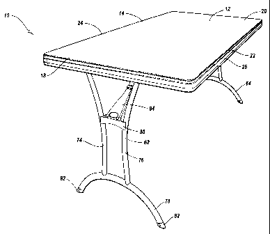
[0067] As shown in Figures 1 and 2, the table 10 includes a table top 12 with
an upper
surface 14, a lower surface 16, a first end 18, a second end 20, a front side
22 and a rear side
24. The upper surface 14 of the table top 12 is preferably generally planar to
create a
smooth, flat working surface, but the upper surface could also be textured and
have other
suitable configurations depending, for example, upon the intended use of the
table 10. The
table top 12 may also include an edge 26 that is disposed about the outer
perimeter or
periphery of the table top. All or a portion of the edge 26 may be beveled,
sloped or
rounded to, for example, increase the comfort and safety of the user. The
table top 12 may
also include a downwardly extending lip 28 disposed near or at the outer
portion of the table
top. The lip 28 preferably extends downwardly beyond the lower surface 16 of
the table top
12 and the lip may be aligned with or form a part of the edge 26 of the table
top. It will be
appreciated that the lip 28 may also be spaced inwardly from the edge 26 of
the table top 12.
Various embodiments of a lip that may be used in conjunction with the table
top 12 are
CA 02469892 2004-06-09
WO 03/086146 PCT/US03/10875
19
disclosed in Assignee's co-pending United States patent application serial no.
10/096,814,
entitled Portable Folding Utility Table with Integral Table Top and Lip, which
is hereby
incorporated by reference in its entirety.
[0068] The table top 12 preferably has a generally rectangular configuration
with
rounded corners and slightly rounded edges 26. Desirably, the table top 12 has
a relatively
large size and it is configured for use as a banquet style table. In
particular, the table top 12
may have a length of about five feet (or about sixty inches) and a width of
about two and
one-half feet (or about thirty inches), but the table top can be larger or
smaller. For
example, the table top 12 could be six or eight feet in length, and the table
top could be two
or three feet in width. One skilled in the art will appreciate that the table
top 12 can be
larger or smaller according, for example, to the intended use of the table 10.
Additionally,
the table top 12 may have other suitable shapes and configurations such as
square, circular,
oval, and the like depending, for example, upon the intended use of the table
10. In
addition, the corners and edges 26 of the table top 12 do not have to rounded
and, in
contrast, the corners and edges could have any desirable configuration, but
the rounded
features may increase the comfort and/or safety of the user. Further, the
table top 12 could
be sized and configured for use with other types of tables such as utility
tables, card tables,
personal-sized tables, and the like.
[0069] The table top 12 is preferably constructed from a lightweight material
and, more
preferably, the table top is constructed from plastic, such as high density
polyethylene. The
plastic table top 12 is desirably formed by a blow-molding process because,
for example, it
allows a strong, lightweight, rigid and sturdy table top to be quickly and
easily
manufactured. Advantageously, the blow-molded plastic table top 12 is lighter
weight that
conventional table tops constructed from wood or metal. The blow-molded
plastic table top
CA 02469892 2004-06-09
WO 03/086146 PCT/US03/10875
12 is lightweight because it is substantially hollow. It will be appreciated
that the
substantially hollow table top 12 can include table tops that are generally
hollow or
completely hollow.
[0070] The table top 12 is preferably constructed from blow-molded plastic
because
blow-molded plastic table tops are relatively durable, weather resistant,
temperature
insensitive, corrosion resistant, rust resistant, and blow-molded plastic
generally does not
deteriorate over time. One skilled in the art, however, will appreciate that
the table top 12
does not have to be constructed from blow-molded plastic and other suitable
materials
and/or processes can be used to construct the table top such as other types of
plastics,
polymers and synthetic materials. In addition, the table top 12 may be
constructed from
other materials with sufficient strength and desirable characteristics such as
plywood,
particle board, solid wood, wood slates, metal alloys, fiberglass, ceramics,
graphite, and the
like.
[0071] The upper surface 14 and the lower surface 16 of the table top 12 are
spaced
apart a given distance and these two spaced apart surfaces help create a rigid
and strong
table top 12. Preferably, the upper surface 14 and the lower surface 16 are
separated by a
generally constant distance so that the surfaces are generally aligned in
parallel planes. The
upper and lower surfaces 14, 16 of the table top 12 may also be interconnected
by one or
more tack-offs, kiss-offs or depressions 30, or other reinforcement
structures, which may be
sized and configured to further increase the strength and rigidity of the
table top 12.
Advantageously, the depressions 30 and/or other reinforcement structures can
be integrally
formed as part of a unitary, one-piece table top 12 during the blow-molding
process.
[0072] The depressions 30 are preferably located in the lower surface 16 of
table top 12
and the depressions are preferably sized and configured to increase the
strength and
CA 02469892 2004-06-09
WO 03/086146 PCT/US03/10875
21
structural integrity of the table top. The depressions 30 preferably extend
towards the upper
surface 14 of the table top and the ends of the depressions 30 may contact or
engage the
upper surface of the table top 12, or the ends of the depressions may be
spaced from the
upper surface of the table top. As shown in Figures 2 and 3, the depressions
30 preferably
cover substantially the entire lower surface 16 of the table top 12, but it
will be appreciated
that the depressions may cover only a portion of the table top. Additionally,
while the
depressions 30 are shown and described as being located in the lower surface
16 of the table
top 12, it will be appreciated that the depressions could be formed in any
desired portion of
the table top. For example, it will be appreciated that one or more
depressions 30 may be
formed in the upper surface 14 of the table top 12 and one or more depressions
may be
formed in the lower surface 16 of the table top, and these opposing
depressions may be
generally aligned. At least a portion of these opposing depressions 30 may
contact or
engage each other, but the opposing depressions do not have to touch or
engage.
[0073] The depressions 30 are preferably arranged into a predetermined pattern
or array
in order to increase the strength and structural integrity of the table top
12. In particular, the
depressions 30 are preferably spaced closely together in a predetermined
pattern such that
the distance between the depressions is minimized. Advantageously, minimizing
the
distance between the depressions 30 may minimize the unsupported areas of the
upper
surface 14 of the table top 12, which may increase the smoothness of the upper
surface of
the table top. In addition, minimizing the distance between the depressions 30
may increase
the structural integrity and strength of the table top 12. Thus, the
depressions 30 are
desirably closely spaced on the lower surface 16 of the table top 12 such that
the depressions
are separated by a minimum distance in order to create a table top with
greater strength,
structural integrity, and an upper surface 14 with increased smoothness.
CA 02469892 2004-06-09
WO 03/086146 PCT/US03/10875
22
[0074] Advantageously, the increased structural integrity and strength of the
table top 12
may allow the outer wall thickness of the table top to be decreased, which may
allow less
plastic to be used to construct the table 10. Because less plastic may be
required to construct
the table top 12, that may allow the cost of the table 10 to be decreased. In
addition, the
blow-molded table top 12 may cool more quickly during the manufacturing
process because
of the thinner outer wall. This allows the table top 12 to be removed from the
manufacturing mold more quickly and it may allow the table top to be removed
at a higher
temperature because it dissipates heat much more rapidly. Significantly,
because the cycle
time required to construct the table top 12 may be decreased, the
manufacturing efficiency
may be increased.
[0075] The depressions 30 are also preferably arranged in a predetermined
pattern with a
generally constant and uniform spacing so that the table top 12 has generally
uniform
characteristics. In particular, the depressions 30 are preferably arranged
into a uniform
pattern across the entire surface of the table top 12 so that the strength,
structural integrity
and/or other characteristics of the table top are generally uniform throughout
the table top.
Thus, the table top 12 has fewer, if any, weak, or unsupported portions which
decrease the
strength and structural integrity of the table top. Thus, the depressions 30
may be used to
create a table top 12 with generally uniform characteristics throughout the
table top.
[0076] Desirably, other features formed in the table top 12 are sized and
configured such
that they do not significantly disturb or disrupt the desired pattern of
depressions 30. In
addition, the depressions 30 are preferably integrally formed in the table top
12 as part of a
unitary, one-piece structure. Advantageously, the depressions 30 can be
integrally formed in
the table top 12 during the blow-molding process. Additional details regarding
the size,
shape and configuration of depressions that are suitable for use in connection
with the table
CA 02469892 2004-06-09
WO 03/086146 PCT/US03/10875
23
top 12 are disclosed in Assignee's co-pending United States patent application
serial no.
(attorney docket no. 15499.370) entitled High-Strength, Lightweight Blow-
molded Plastic Structures, which is hereby incorporated by reference in its
entirety.
[0077] As best seen in Figures 3, 3A and 4, a frame 32 is connected to the
lower surface
16 of the table top 12. The frame 32 desirably includes two side rails 34 that
extend along
the length of the table top 12 and the side rails are preferably positioned
near opposing edges
26 of the table top. In particular, the side rails 34 are preferably disposed
inwardly from the
lip 28 such that there is a gap or space between the side rails and the lip.
The side rails 34
preferably extend almost the entire length of the table top 12 to provide
increased strength
and rigidity for the table top, but the side rails may extend along only a
portion of the length
of the table and the side rails may not be required to provide increased
strength or rigidity to
the table top.
(0078] The frame 32 is desirably constructed from metal, which may easily be
formed
into the desired configuration by known operations such as stamping and
bending, and the
metal may be coated or painted as desired. The frame 32 may also include one
or more end
rails attached to the ends of the side rails 34 and the frame may provide
attachment points
for the legs, as discussed in more detail below. While the frame 32 preferably
includes two
side rails 34 that are generally aligned in a parallel configuration, it will
be appreciated that
the frame may have other suitable configurations and arrangements depending,
for example,
upon the size and shape of the table top 12 or the intended use of the table
10.
[0079] The frame 32 is desirably connected to the lower surface 16 of the
table top 12
by one or more frame mounting portions 36 that allow the frame to be connected
to the table
top by a snap, friction or interference fit. Advantageously, the connection of
the frame 32 to
the table top 12 does not require the use of mechanical fasteners such as
bolts or screws,
CA 02469892 2004-06-09
WO 03/086146 PCT/US03/10875
24
which desirably expedites the manufacturing or assembly process, but fasteners
may be used
if desired. Additionally, because screws, bolts and other types of mechanical
fasteners are
not required to attach the frame 32 to the table top 12, no holes or other
types of stress
concentrations are formed in the table top. Thus, the strength and structural
integrity of the
table top 12 is not compromised by drilling holes in the table top. In
addition, because the
frame 32 is preferably not bonded to the lower surface 16 of table top 12, the
table top is not
weakened or damaged by adhesive. Thus, strength and integrity of the table top
12 may be
retained because the frame 32 is not screwed, bolted or bonded directly to
lower surface 16
of the table top. Further, the attachment of the frame 32 to the frame
mounting portions 36
may reduce the likelihood of deformation or damage to the table top. Finally,
the
connection of the frame 32 to the table top 12 without using mechanical
fasteners or
adhesive may facilitate assembly of the table 10 by the retailer or consumer.
[0080] The frame mounting portions 36 are sized and configured to retain the
frame 32
in a generally fixed position and to prevent the unintended removal of the
frame from the
table top 12. The frame mounting portions 36 desirably have about the same
length as the
side rails 34 and this allows the frame 32 to be connected to the frame
mounting portions
along the entire length of the side rails. Advantageously, any forces acting
on the table top
12 and/or the frame 32 are distributed over a large area. In contrast,
conventional tables that
attached the frame to the table top by mechanical fasteners distributed forces
over a much
smaller area, which makes conventional tables much more likely to fail.
Therefore, the
frame mounting portions 36 may provide a very secure attachment of the frame
32 to the
table top 12 even though mechanical fasteners are not required. It will be
appreciated that
the frame mounting portions 36 may have a length less than the frame 32 so
that only
portions of the frame are attached to the frame mounting portions.
CA 02469892 2004-06-09
WO 03/086146 PCT/US03/10875
[0081] As best seen in Figures 3A and 4, the side rails 34 of the frame 32
preferably
have a generally U-shaped configuration with a first side 38, a second side
40, and a
connecting portion 42. The first side 38 of the side rail 34 includes an
engaging portion 44
and the second side 40 includes an engaging portion 46. The engaging portions
44, 46 are
spaced apart a distance and the engaging portions are sized and configured to
securely attach
the side rails 34 of the frame 32 to frame mounting portions 36. Because the
frame
mounting portions 36 are desirably integrally formed in the table top 12 as
part of a unitary,
one-piece structure, the frame 32 can be directly attached to the table top
12.
[0082] As shown in Figure 3A, the frame mounting portion 36 includes an
opening 48
and a recess 50 that is sized and configured to receive a portion of the side
rails 34. In
particular, the opening 48 to the frame mounting portion 36 is preferably
slightly smaller
than the distance separating the engaging portions 44, 46 of the side rails
34. Thus, when
the engaging portions 44, 46 of the side rails 34 are inserted into the
opening 48, the
engaging portions 44, 46 must deflect inwardly and/or the opening must deform
to allow the
side rails to be inserted into the recess 50 of the frame mounting portion 36.
Once the
engaging portions 44, 46 are inserted into the recess 50, the engaging
portions and/or the
opening 48 resiliently or elastically return to there respective original
positions to secure the
side rail 34 within the frame mounting portion 36.
[0083] The engaging portions 44, 46 of the side rails 34 may engage one or
more
corresponding surfaces within the recess 50 to help secure the frame 32 to the
table top 12.
As seen in Figures 3A and 4, the engaging portions 44, 46 are preferably the
ends of the first
side 38 and second side 40 of the side rail 34 that are bent outwardly at an
angle less than
about 90° relative to the first and second sides, respectively. The
engaging portions 44, 46
preferably include sharp edges 52 that are sized and configured to engage
corresponding
CA 02469892 2004-06-09
WO 03/086146 PCT/US03/10875
26
side walls 54, 56 of the recess 50. Advantageously, the sharp edges 52 engage
and bite into
the softer, blow-molded plastic material of the recess 50 to allow the frame
32 to be securely
connected to the table top 12. Significantly, the engagement of the engaging
portions 44, 46
and the edges 52 to the recess 50 provides a large contact area between the
frame 32 and the
frame mounting portions 36.
[0084] As seen in Figures 2, 3 and 3A, the frame mounting portions 36 are
formed in the
lower surface 16 of the table top 12 and one or more depressions 30 are
preferably formed in
the lower portion of the recess 50 so that a generally consistent, uniform
pattern of
depressions is formed in the table top 12. Advantageously, this helps create a
table top 12
with increased strength, structural integrity and generally uniform
characteristics. One
skilled in the art will appreciate that the depressions 30 could have other
suitable
arrangements and depressions do not have to be formed in the lower portion of
the recess 50.
[0085] In addition, because at least a portion of the side rails 34 are
inserted into the
recesses S0, the side rails and the connecting portion 42 of the frame 32 do
not extend a
large distance away from the lower surface 16 of the table top 12. This may
allow a table 10
with a low profile to be designed and manufactured. Significantly, if the
height of the table
top 12 is relatively small, then the tables 10 may be more easily stacked.
This may assist in
the shipping and storage of the tables 10. Additionally, the lip 28 may have a
height that is
larger than or equal to the distance that the side rails 34 extend from the
lower surface 16 of
the table top 12 so that the frame is generally hidden from view when the
table 10 is viewed
from a plane generally aligned with the upper surface 14 of the table top 12.
Advantageously, because the frame 32 may be completely or generally hidden
from view,
the frame does not have to be finished and it may contain visible
imperfections or flaws. In
addition, because the frame 32 may be completely or generally hidden from view
by the lip
CA 02469892 2004-06-09
WO 03/086146 PCT/US03/10875
27
28, a more aesthetically pleasing table 10 may be created. It will be
appreciated, however,
that the lip 28 does not have to hide all or a portion of the frame 32 from
view.
[0086] As shown in the accompanying figures, the frame 32 engages or abuts
several
different surfaces of the frame mounting portions 36 to securely attach the
frame to the table
top 12. The engagement of the side rails 34 to several different surfaces of
the frame
mounting portions 36 over an extended length allows any forces or loads on the
table top 12
and the frame 32 to be distributed over a large area, which helps prevent
failure of the table
10. Additionally, because the engaging portions 44, 46 of the side rails 34
preferably extend
outwardly and are spaced wider apart than the opening 48 to the frame mounting
portions
36, a secure snap, friction or interference connection of the frame 32 to the
table top 12 may
be established. Further, the side rails 34 and the frame mounting portions 36
are preferably
generally symmetrical to help prevent undesirable twisting of the frame 32
and/or table top
12.
[0087] Advantageously, the frame 32 can be quickly and easily connected to the
table
top 12 by inserting the engaging portions 44, 46 of the side rails 34 into the
openings 48 in
the frame mounting portions 36. As discussed above, mechanical fasteners such
as screws
or bolts are not required to connect the frame 32 to the table top 12, but
such fasteners may
be used if desired. In addition, the frame 32 can be more easily disconnected
from the table
top 12, if desired, because mechanical fasteners do not have to be removed.
[0088] As best seen in Figures 4, 6 and 7, the side rails 34 of the frame 32
include
openings 60 that are sized and configured to allow legs 62, 64 to be attached
to the table 10.
The legs 62, 64 are sized and configured to support the table top 12 above a
surface such as
a floor and the legs may be adjustable in length. T'he legs 62, 64 are
preferably disposed
between the side rails 34 of the frame and the openings 60 are preferably
located near the
CA 02469892 2004-06-09
WO 03/086146 PCT/US03/10875
28
ends of the side rails 34 in generally aligned pairs. It will be appreciated
that the openings
60 could be positioned in any desired locations depending, for example, the
configuration of
the legs 62, 64 and/or the frame 32.
[0089] The openings 60 preferably have a non-circular configuration such as
oval,
oblong, egg-shaped, kidney-shaped, key-shaped, etc., which is sized and
configured to
receive a portion of the legs 62, 64. As shown in the accompanying figures,
the openings 60
include a length 66 that is generally aligned with the longitudinal length of
the side rails 34
and a height 68 that is generally aligned with the height of the side rails.
It will be
appreciated that one or more bushings, sleeves, bearings, and the like may be
used in
conjunction with openings 60 to facilitate the connection of the legs 62, 64
to the frame.
[0090] The legs 62, 64, which are movable between a first extended position in
which
the legs extend away from the table top 12 and a second collapsed position in
which the legs
are positioned near the table top for storage, include a connecting rod 70
that is sized and
configured to be inserted into the openings 60 in the side rails 34 of the
frame 32. The
rotation of the connecting rod 70 within the opening 60 allows the legs 62, 64
to move
between the first and second positions relative to the table top 12.
[0091] As best seen in Figures 2 and 3, the lower surface 16 of the table top
12 includes
receiving channels 72 that are sized and configured to receive at least a
portion of the legs
62, 64 in the collapsed position. The receiving channels 72 advantageously
receive at least a
portion of the legs 62, 64 to decrease the height of the table 10 in the
storage position. This
allows more tables 10 to be stacked and stored in a limited amount of space,
and this may
facilitate shipping and transportation of the tables. As shown in the
accompanying figures,
one or more depressions 30 are preferably located in the receiving channels 72
so that the
consistent pattern and arrangement of depressions is maintained. It will be
appreciated,
CA 02469892 2004-06-09
WO 03/086146 PCT/US03/10875
29
however, that depressions 30 do not have to be formed in the receiving
channels 72 and
receiving channels do not have to be formed in the table top 12.
[0092] The connecting rod 70 preferably has a non-circular cross-sectional
configuration
and the openings 60 in the side rails 34 of the frame 32 also preferably have
a non-circular
configuration. For example, the openings 60 and the connecting rod 70 may have
a
configuration that is oval, oblong, egg-shaped, kidney-shaped, key-shaped,
etc. Desirably,
the non-circular opening 60 and the non-circular cross-sectional configuration
of the
connecting rod 70 are sized and configured such that the connecting rod is not
securely held
within the opening when the legs are in the collapsed position. Thus, in the
collapsed
position, one or more small gaps or spaces are located between connecting rod
70 and the
opening 60 so that the connecting rod can move slightly within the opening.
Advantageously, this allows the legs 62, 64 to be more easily connected to the
side rails 34
because of the larger clearance.
[0093] Additionally, because there is some movement or "play" between the legs
62, 64
and the side rails 34 when the legs are in the collapsed position, that may
allow the legs to
fold flatter such that the legs contact and/or are generally parallel to the
lower surface 16 of
the table top 12. Further, the movement of the legs 62, 64 within the openings
60 may allow
the legs to be positioned in the desired collapsed position even if, for
example, there is some
slight imperfection in the table 10 or if a portion of the table has expanded
or contracted due
to temperature. Accordingly, the tables 10 may be more easily manufactured and
assembled
because of the greater tolerances, and the tables may fold flatter to
facilitate stacking of the
tables.
[0094] When the legs 62, 64 are in the extended position, however, the
connecting rod
70 is preferably securely held within the openings 60 to rigidly and securely
attach the legs
CA 02469892 2004-06-09
WO 03/086146 PCT/US03/10875
to the table top 12. In particular, when the connecting rod 70 is rotated
within the openings
60 to the extended position, the connecting rod and openings are sized and
configured such
that there is no or very little movement or play between the connecting rod
and the openings.
Thus, the legs 62, 64 desirably do not shake or wobble in the extended
position.
[0095] For example, the openings 60 in the side rail 34 may have a height of
about 0.94
(15/16) inches and an overall length of about 1.5 inches, and the connecting
rod 70 may
have an oval configuration with a height of about 0.94 (15/16) inches and a
width of about
0.75 (3/4) inches. Advantageously, these sizes and configurations allow the
connecting rod
70 to be relatively easily inserted into the openings 60 and the connecting
rod can move
slightly within the opening when the legs 62, 64 are in the collapsed
position. In particular,
as best seen in Figure 6, the connecting rod 70 can move within the opening 60
because
there are gaps or spaces between the connecting rod and the opening. On the
other hand,
when the legs 62, 64 are in the extended position, the connecting rod 70 is
securely held
within the opening 60. As best seen in Figure 7, the upper and lower ends of
the connecting
rod 70 engage the upper and lower portions of the opening 60 when the legs 62,
64 are in the
extended position.
[0096] It will be appreciated that the openings 60 and connecting rod 70 can
have other
suitable sizes and configurations depending, for example, upon the size and/or
intended use
of the table 10. It will also be appreciated that other suitable combinations
of the openings
60 and connecting rod 70 may be utilized, such as the combination of generally
circular
openings and non-circular connecting rods, or non-circular openings and
generally circular
connecting rods. Further, it will be appreciated that the legs 62, 64 may be
attached to the
frame 32 or table top 12 by other suitable types of devices and mechanisms.
CA 02469892 2004-06-09
WO 03/086146 PCT/US03/10875
31
[0097] The legs 62, 64, as best seen in Figures 4 and 5, are attached to or
include the
connecting rod 70 and the legs include a pair of elongated support members 74,
76 and a
foot portion 78. Advantageously, the two separate elongated support members
74, 76 may
help prevent twisting or torque on the connection of the support members to
the connecting
rod 70 and the foot portion 78. Additionally, while the elongated support
members 74, 76
are preferably welded to the connecting rod 70 and the foot portion 78, the
support members
may be connected to the connecting rod and foot portion by any suitable method
or device.
[0098] As best seen in Figure 5, the elongated support members 74, 76
preferably have a
generally curved configuration. In particular, the upper portions of the
elongated support
members 74, 76 are preferably spaced apart to provide a secure attachment of
the support
members to the connecting rod 70, the middle portions of the elongated support
members
are preferably more closely spaced together, and the lower portions of the
elongated support
members are spaced apart to provide a secure connection to the foot portion
78. The foot
portion 78 preferably has an upwardly extending curved section and feet 82 may
be
connected to the ends of the foot portion. A connecting member 80 is
preferably disposed
near the middle portion of the elongated support members 74, 76 to help
maintain the
support members in the desired positions.
[0099] The connecting rod 70, elongated support members 74, 76 and foot
portion 78 of
the legs 62, 64 are desirably constructed from hollow metal tubes because the
metal tubes
are relatively lightweight and strong. The hollow metal tubes forming the
connecting rod
70, elongated support members 74, 76 and foot portion 78 desirably have a
generally oval
configuration to provide increased strength. Advantageously, the oval
configuration may
also be used to create a thinner profile for the legs 62, 64, which may create
a thinner profile
for the table 10 when the legs are in the collapsed position.
CA 02469892 2004-06-09
WO 03/086146 PCT/US03/10875
32
[00100] It will be appreciated that the legs 62, 64 may be constructed from
other
materials with the suitable characteristics and the legs may have other shapes
and
configurations depending, for example, upon the intended use of the table 10.
For example,
the legs 62, 64 may include only a single elongated support member or multiple
elongated
support members, and the legs may be constructed as a single component or
multiple
components that are connected together. It will further be appreciated that
the legs 62, 64
need not be in pivotal engagement with frame 32 or the table top 12 to be
collapsible. For
example, the legs 62, 64 may be detachably connected to the table top 12 such
that when it
is desired to collapse the table 10 for storage, the legs are detached from
the table top. Other
suitable embodiments for connecting legs to a table top are disclosed in
Assignee's co-
endin United States atent a lication serial no.
p g p pp , (attorney docket no.
15499.403) entitled Pivotal Connection of a Table Leg to a Frame, which is
hereby
incorporated by reference in its entirety.
[00101] A support brace 84 is used to support the legs 62, 64 in the extended
position.
The support brace 84 includes a first end 86 that is attached to the leg 62,
64 and a second
end 88 that is attached to the table top 12 by a mounting member or bracket
90. The support
brace 84 is preferably pivotally connected to the leg 62, 64 and the bracket
90 to allow the
leg to be moved between the extended and collapsed positions. It will be
appreciated that
while the legs 62, 64 are in the extended or collapsed positions, the support
brace 84 is also
in a corresponding extended or collapsed position. Advantageously, the support
brace 84
can be connected to the leg 62, 64 and the bracket 90 without the use of
mechanical
fasteners such as screws, rivets or bolts. Significantly, the table 10 may be
built more
quickly because fewer components may be required to assemble the table and no
mechanical
fasteners are needed to attach the support brace 84 to the legs 62, 64 or the
table top 12. It
CA 02469892 2004-06-09
WO 03/086146 PCT/US03/10875
33
will be appreciated, however, that one or more mechanical fasteners may be
used to connect
the support brace 84 to the leg 62, 64 and/or the table top 12.
[00102] In greater detail, as best seen in Figures 10, 11 and 12, the first
end 86 of the
support brace 84 includes two curved arms 92 and each curved arm has an
opening 94 that
leads to a generally circular interior portion 96. The two generally circular
interior portions
96 are generally aligned along the same axis and disposed at the end 86 of the
support brace
84. The generally circular interior portions 96 are sized and configured to
receive
corresponding receiving portions 98 formed in the connecting member 80. In
particular, the
receiving portions 98 include a flange 100 with rounded ends 102 and
corresponding
openings 104. The support brace 84 is connected to the leg 62, 64 by disposing
the rounded
ends 102 of the flange 100 within the generally circular interior portions 96
of the curved
arms 92. In addition, the curved arms 92 of the support brace 84 are disposed
within the
openings 104 in the connecting member 80. Advantageously, when the support
brace 84 is
connected to the legs 62, 64 and the table top 12, the support brace cannot be
inadvertently
disconnected from the legs. While this connection of the support brace 84 to
the leg 62, 64
does not require that use of any mechanical fasteners, it will be appreciated
that mechanical
fasteners may be used to connect the support brace to the legs 62, 64.
[00103] In order to attach the support brace 84 to the leg 62, 64, the two
generally
circular interior portions 96 of the curved arms 92 are coaxially aligned with
the rounded
ends 102 of the flange 100. The rounded ends 102 of the flange 100 are then
inserted into
the generally circular interior portions 96 of the support brace 84 and the
arms 92 are
inserted into the openings 104 in the flange. Significantly, when the second
end 88 of the
support brace 84 is attached to the table top 12, the first end 86 of the
support brace cannot
be disconnected from the leg 62, 64. This helps create a strong and secure
table 10 because
CA 02469892 2004-06-09
WO 03/086146 PCT/US03/10875
34
the support brace 84 cannot be unintentionally disconnected from leg 62, 64
when the table
is assembled. However, when the second end 88 of the support brace 84 is
disconnected
from the table 10, then the first end 86 of the support brace can be
disconnected from the leg
62, 64. This allows the table 10 to be quickly and easily assembled, and it
allows the table
to be quickly and easily disassembled.
[00104] The brackets 90, as best seen in Figures 3 and 3B, are connected to
the lower
surface 16 of the table top 12 by bracket mounting portions 110 that allow the
brackets to be
connected to the table top by a snap, friction or interference fit.
Advantageously, the
connection of the brackets 90 to the table top 12 does not require the use of
mechanical
fasteners such as bolts or screws, which desirably expedites the manufacturing
or assembly
process, but fasteners may be used if desired. Additionally, because screws,
bolts or other
types of mechanical fasteners are not required to attach the brackets 90 to
the table top 12,
no holes or other types of stress concentrations are formed in the table top.
Thus, the
strength and structural integrity of the table top 12 is not diminished by
drilling or forming
holes in the table top. In addition, because the brackets 90 are preferably
not glued to the
lower surface 16 of table top 12, the table top is not weakened or damaged by
adhesive.
Thus, strength and integrity of the table top 12 may be retained because the
brackets 90 are
not screwed, bolted or bonded to bottom surface 16 of the table top. Further,
the connection
of the brackets 90 to the table top 12 without using mechanical fasteners or
adhesives may
facilitate assembly of the table 10 by the retailer or consumer.
[00105] The bracket mounting portions 110 are sized and configured to retain
the
brackets 90 in generally fixed positions and to prevent the unintended removal
of the
brackets from the table top 12. Advantageously, the brackets 90 engage a
relatively large
portion of the table top 12 so that forces applied to the brackets are
distributed over a large
CA 02469892 2004-06-09
WO 03/086146 PCT/US03/10875
area. This provides an improved and more secure connection of the brackets 90
to the table
top 12 because forces are distributed over a much larger area than brackets
attached to a
table top only by mechanical fasteners. Additionally, the connection of the
brackets 90 to
the table top 12 by the bracket mounting portions 110 may be less likely to
fail than
conventional brackets attached to a table top by mechanical fasteners because
of the larger
engagement area.
[00106] As best seen in Figure 3B, the bracket 90 includes a main body portion
112 with
a first end 114 and a second end 116. The first end 114 of the bracket 90
includes an
engaging portion 118 with a rounded flange 120 and an edge 122. The second end
116 of
the bracket 90 includes a retaining portion 124 with a first angled portion
126 and a second
angled portion 128. The first angled portion 126 is preferably disposed at an
angle less than
about 90° with respect to the main body portion. 112 of the bracket 90
so that it is angled
towards the first end 114 of the bracket 90. As discussed below, the engaging
portion 118
and the retaining portion 124 are sized and configured to securely attach the
bracket 90 to
bracket mounting portion 110 by a snap, friction or interference fit.
Additionally, the
bracket 90 is preferably directly attached to the table top 12 because the
bracket mounting
portions 110 are desirably integrally formed in the table top as part of a
unitary, one-piece
structure. It will be appreciated, however, that the bracket 90 does not have
to be directly
attached to the table top 12 and the bracket does not have to be attached to
the table top by
the bracket mounting portions 110.
[00107] As shown in Figure 3B, the bracket mounting portion 110 includes a
first recess
130 and a second recess 132 that are sized and configured to receive the first
end 114 and
the second end 116 of the bracket 90, respectively. In particular, the first
recess 130 is
disposed towards the middle of the table top 12 and the first recess
preferably has a length
CA 02469892 2004-06-09
WO 03/086146 PCT/US03/10875
36
that is approximately the same as the length of the first end 114 of the
bracket 90. A
protrusion or lip 134 projects into an upper portion of the first recess 130
and it is sized and
co~gured to fit within the inner portion of the rounded flange 120 on the
first end 114 of
the bracket 90. The second recess 132 is disposed towards the end of the table
top 12 and it
has a length that is approximately the same as the length of the second end
116 of the
bracket 90. A protrusion or lip 136 extends into an upper portion of the
second recess 132
and it is sized and configured to contact or abut at least a portion of the
first downwardly
extending portion 126 on the second end 116 of the bracket 90. The distance
from the first
edge 122 on the first end 114 of the bracket 90 to the innermost part of the
first downwardly
extending portion 126 on the second end 116 of the bracket is preferably
smaller than the
distance from the protrusion 134 extending into the first recess 130 to the
protrusion 136
extending into the second recess 132 of the bracket mounting portion 110,
which allows the
bracket to be connected to the bracket mounting portion 110 by a snap,
friction or
interference fit.
[00108] In order to connect the bracket 90 to the table top 12, the engaging
portion 118
on the first end 114 of the bracket is inserted into the first recess 130 of
the bracket
mounting portion 110 such that the rounded flange 120 and the edge 122 engage
a portion of
the table top 12. In particular, the edge 122 preferably engages a portion of
the first recess
130 and/or the protrusion 134 and the rounded flange 120 contacts or abuts at
least a portion
of the protrusion. The second end 116 of the bracket 90 is then inserted into
the second
recess 132 of the bracket mounting portion 110. As the retaining portion 124
on the second
end 116 of the bracket 90 is inserted into the second recess 132, the first
angled portion 126
and/or the protrusion 136 deflects or deforms to allow the second end of the
bracket to be
inserted into the recess. Once the second end 116 of the bracket 90 is
inserted into the
CA 02469892 2004-06-09
WO 03/086146 PCT/US03/10875
37
second recess 132, the first angled portion 126 and/or the protrusion 136
resiliently or
elastically returns to there original positions to secure the second end of
the bracket in a
fixed position. Accordingly, the bracket 90 is preferably connected to the
bracket mounting
portion 110 of the table top 12 by a snap, friction or interference fit, and
this allows the
bracket to be securely connected to the table top without the use of
fasteners. It will be
appreciated, however, that fasteners or adhesives could also be used to secure
the bracket 90
to the table top 12 if desired.
[00109] The rounded flange 120 on the first end 114 of the bracket 90
preferably has a
radius of curvature that generally corresponds to the radius of curvature of
the protrusion
134 to help secure the bracket 90 to the bracket mounting portion 110.
Similarly, the first
angled portion 126 on the second end 116 of the bracket 90 preferably has a
radius of
curvature that generally corresponds to the radius of curvature of the
protrusion 136. This
provides a large contact area between the bracket 90 and the bracket mounting
portion 110.
Additionally, the edge 122 on the first end 114 of the bracket 90 is
preferably sharp so that it
engages and bites into the softer, blow-molded plastic material of the table
top 12 to allow
the bracket 90 to be securely connected to the table top. Significantly, the
engagement of
the first end 114 and the second end 116 of the bracket 90 to the first recess
130 and the
second recess 132 of the bracket mounting member 110, respectively, provides a
large
contact area that allows forces or loads on bracket to be distributed over a
large area, which
helps provide a secure and durable connection of the support brace 84 to the
table top 12.
[00110] As seen in Figure 2, the bracket mounting portions 110 are formed in
the lower
surface 16 of the table top 12 and one or more depressions 30 may be formed in
the bracket
mounting portions so that a generally consistent, uniform pattern of
depressions is formed in
the table top 12. Significantly, all or only a portion of the depressions 30
may be formed in
CA 02469892 2004-06-09
WO 03/086146 PCT/US03/10875
38
the bracket mounting portions 110 in order to maintain the generally uniform
pattern of
depressions. Advantageously, the uniform pattern of depressions 30 may help
create a table
top 12 with increased strength, structural integrity and generally uniform
characteristics.
One skilled in the art will appreciate that the depressions 30 could have
other suitable
arrangements and depressions do not have to be formed in the bracket mounting
portions
110.
[00111] As discussed above, the second end 88 of the support brace 84 is
connected to
the bracket 90. As best seen in Figures 4 and 14, the second end 88 of the
support brace
includes two curved arms 93 and each curved arm has an opening 95 that leads
to a
generally circular interior portion 97. The two generally circular interior
portions 97 are
generally aligned along the same axis and disposed near the end of the support
brace 84.
The generally circular interior portions 97 are sized and configured to be
connected to the
second end 116 of the bracket 90. In particular, the generally circular
interior portions 97
are sized and configured to receive a portion of the first angled portion 126
and the second
angled portion 128 of the bracket 90. In addition, the curved arms 93 of the
support brace
84 are configured to be disposed within openings 99 in the second end 116 of
the bracket 90.
Advantageously, when the support brace 84 is connected to the legs 62, 64 and
the table top
12, the support brace cannot be inadvertently disconnected from the bracket
90. While this
connection of the support brace 84 to the bracket 90 does not require that use
of any
mechanical fasteners, it will be appreciated that mechanical fasteners may be
used to
connect the support brace to the bracket.
[00112] In order to attach the support brace 84 to the bracket 90, the two
generally
circular interior portions 97 of the curved arms 93 are coaxially aligned with
the first angled
portion 126 and the second angled portion 128 on the second end 116 of the
bracket. The
CA 02469892 2004-06-09
WO 03/086146 PCT/US03/10875
39
first angled portion 126 and the second angled portion 128 are then inserted
into the
generally circular interior portions 97 of the support brace 84 and the curved
arms 93 are
inserted into the openings 99 in the second end 116 of the bracket 90.
Significantly, when
the support brace 84 is connected to the bracket 90 and the bracket is
connected to the table
top 12, the support brace cannot be disconnected from the bracket. This helps
create a
strong and secure table 10 because the support brace 84 cannot be
unintentionally
disconnected from bracket 90 when the table is assembled. However, when the
bracket 90 is
disconnected from the table top 12, then the second end 88 of the support
brace 84 can be
disconnected from the bracket. This allows the table 10 to be quickly and
easily assembled
and disassembled.
[00113] As discussed above, the first end 86 of the support brace 84 may be
pivotally
connected to the legs 62, 64 and the second end 88 of the support brace may be
pivotally
connected to the bracket 90. One skilled in the art, however, will appreciate
that the ends
86, 88 of the support brace 84 do not have to be pivotally connected to the
legs 62, 64 or the
bracket 90. Other suitable embodiments for connecting the support brace to the
legs and/or
the table top are disclosed in Assignee's co-pending United States patent
application serial
no. , (attorney docket no. 15499.401 ) entitled Pivotal Connection of a
Support Brace to a Table Leg and Table Top, which is hereby incorporated by
reference in
its entirety.
[00114] As best seen in Figures 7-10, the support brace 84 includes a first
arm 140 that is
pivotally connected to a second arm 142 by a pin 144. The pivotal connection
of the first
and second arms 140, 142 allows the support brace 84 to move between the
extended
position and the collapsed position. When the support brace 84 is in the
collapsed position,
the legs 62, 64 are also in the collapsed position. Similarly, when the
support brace 84 is in
CA 02469892 2004-06-09
WO 03/086146 PCT/US03/10875
the extended position, the legs 62, 64 are also in the extended position.
While the support
brace 84 preferably pivots to allow the legs 62, 64 to be moved between the
extended
position and the collapsed position, it will be understood that the support
brace does not
require the pivotal connection of the first arm 140 and the second arm 142,
and the support
brace 84 could have other suitable arrangements and/or configurations.
[00115) A locking mechanism 146 is preferably used to secure the support brace
84 in the
extended position, which consequently also secures the legs 62, 64 in the
extended position.
Advantageously, the locking mechanism 146 can secure the legs 62, 64 in the
extended
position regardless of the position or orientation of the table 10. Thus, the
legs 62, 64 will
not move from the extended position to the collapsed position even if the
table 10 is turned
on its side or upside-down. In addition, the locking mechanism 146 is
preferably biased to
remain in the locked position and the locking mechanism positively locks the
support brace
84 and the legs 62, 64 in the extended position. Further, the locking
mechanism 140
preferably requires the user to intentionally unlock the mechanism to allow
the support brace
84 and the legs 62, 64 to move into the collapsed position. Thus, the support
brace 84 and
the legs 62, 64 can be positively held in the extended position by the locking
mechanism
146.
[00116] As seen in Figures 8-10, the locking mechanism 146 includes an
elongated body
148 that is generally sized and configured to fit within the second arm 142 of
the support
brace 84. In particular, the second arm 142 of the support brace 84 has a
generally U-shaped
configuration with two opposing sidewalk 150, 152 and the elongated body 148
of the
locking mechanism 146 is generally disposed between the sidewalls and towards
the end of
the second arm nearest the first arm 140. The elongated body 148 of the
locking mechanism
146 includes a first end 154 that is sized and configured to engage the pin
144 and a second
CA 02469892 2004-06-09
WO 03/086146 PCT/US03/10875
41
end 156 with an elongated extension 158. Two outwardly extending tabs or
flanges 160,
162 are disposed between the ends 154, 156 of the locking mechanism 146 and
the tabs
extend through an opening 164 in the second arm 142 of the support brace 84.
The
elongated extension 158 on the second end 156 of the locking mechanism 146
extends
through an opening 166 in a flange 168 extending from the second arm 142 of
the support
brace 84. A biasing member such as a spring 170 is disposed about the
elongated extension
158 and the biasing member is positioned between the flange 168 and the
elongated body
148 of the locking mechanism 146.
[00117] The locking mechanism 146 is movable relative to the second arm 142
between a
locked position in which the elongated body 148 is disposed proximate the end
of the second
arm nearest the first arm 140, and an unlocked position in which the elongated
body is
disposed inwardly from the end of the second arm and away from the first arm.
The spring
170 is desirably sized and configured to bias the locking mechanism 146 into
the locked
position. In this locked position, the first end 154 of the elongated body 148
contacts the pin
144 and the outwardly extending tabs 160, 162 are disposed towards the end of
the second
arm 142 of the support brace 84. In the unlocked position, the first end 154
of the elongated
body 148 is spaced apart from the pin 144 and the outwardly extending tabs
160, 162 are
spaced away from the end of the second arm 142 of the support brace 84. One
skilled in the
art will appreciate that other suitable types of biasing mechanisms may be
used to bias the
locking mechanism 146 into the locked position.
[00118] The first and second arms 140, 142 of the support brace 84 are
generally aligned
and at least a portion of the arms overlap when the support brace is in the
extended position.
In particular, as best seen in Figures 8 and 9, the first arm 140 of the
support brace 84
includes two extensions 172, 174 and the extensions are generally parallel to
and overlap
CA 02469892 2004-06-09
WO 03/086146 PCT/US03/10875
42
portions of the sidewalls 150, 152 of the second arm 142 when the support
brace is in the
extended position. When the locking mechanism 146 is in the locked position,
the locking
mechanism maintains the extensions 172, 174 in the generally parallel and
overlapping
position with the sidewalls 150, 152 of the second arm 142. Specifically, the
outwardly
extending tabs 160, 162 engage the extensions 172, 174 to prevent the first
arm 140 from
moving relative to the second arm 142. Thus, the outwardly extending tabs 160,
162
prevent the first arm 140 from pivoting relative to the second arm 142, and
that maintains
the support brace 84 and the legs 62, 64 in the extended position.
[00119] On the other hand, when the support brace 84 is in the collapsed
position, the
extensions 172, 174 do not overlap portions of the sidewalk 150, 152 of the
second arm 142
of the support brace 84. In contrast, as best seen in Figure 6, the extensions
172, 174 are
spaced away from the second arm 142 of the support brace 84 and at least a
portion of the
second arm may be disposed inside the body of the first arm 140 to form a
small, compact
arrangement. Advantageously, the support brace 84 does not significantly
protrude from the
lower surface 16 of the table top 12 in the collapsed position. This allows a
table 10 with a
relatively small height when the legs 62, 64 are in the collapsed position to
be constructed, if
desired.
[00120] When the locking mechanism 146 is in the unlocked position, the
locking
mechanism does not secure the support brace 84 in the extended position. In
contrast, the
locking mechanism 146 allows the first and second arms 140, 142 of the support
brace 84 to
freely move with respect to each other. In particular, as shown in Figure 10,
when the user
moves the locking mechanism 146 into the unlocked position, the outwardly
extending tabs
160, 162 no longer engage the extensions 172, 174 and that allows the first
and second arms
140, 142 of the support brace 84 to freely rotate. Desirably, when the user
releases the
CA 02469892 2004-06-09
WO 03/086146 PCT/US03/10875
43
locking mechanism 146, the spring 170 causes the locking member to return to
its locked
position.
[00121] As best seen in Figures 6, 9 and 10, the extensions 172, 174 have a
curved front
surface 176 and a generally straight rear surface 178 to positively secure the
locking
mechanism 146 in the locked position, and to allow the support brace 84 to be
moved from
the collapsed position to the extended position without the user unlocking the
locking
mechanism 146. In particular, the curved front surfaces 176 of the extensions
172, 174 are
sized and configured to engage the outwardly extending tabs 160, 162 of the
locking
mechanism 146 when the support brace 84 is moved from the collapsed position
to the
extended position. Specifically, the curved front surfaces 176 engage the
outwardly
extending tabs 160, 162 and push the locking member 146 into the unlocked
position. When
the support brace 84 is in the extended position and the first and second arms
140, 142 are
generally aligned, the curved front surface3 176 of the extensions 172, 174 no
longer engage
the tabs 160, 162 and the spring 170 returns the locking mechanism 146 to the
locked
position. Thus, the locking member 146 allows the support brace 84 to be moved
from the
collapsed position to the extended position without requiring the user to
unlock the locking
mechanism.
[00122] The generally straight rear surfaces 178 of the extensions 172, 174
prevent the
locking mechanism 146 from being inadvertently unlocked and allowing the
support brace
84 to move from the extended position to the collapsed position. In
particular, the generally
straight rear surfaces 178 of the extensions 172, 174 engage the generally
planar lower
surfaces of the tabs 160, 162, and this engagement of the extensions and tabs
prevents the
support brace 84 from moving from the extended position to the collapsed
position. In order
to allow the support brace 84 to move from the extended position to the
collapsed position,
CA 02469892 2004-06-09
WO 03/086146 PCT/US03/10875
44
the user must intentionally unlock the locking mechanism 146, and this allows
the support
brace and the legs 62, 64 to be collapsed.
[00123] Significantly, the locking mechanism 146 is lightweight and includes
few
moving parts. In particular, the locking mechanism 146 is preferably
constructed from
metal and it can be stamped or formed into the desired configuration.
Additionally, the
second arm 140 is preferably constructed from metal and the opening 164,
opening 166 and
flange 168 can be stamped or formed into the desired configuration. While the
first arm
140, second arm 142 and the locking mechanism 146 are preferably unitary
components, it
will be appreciated that these components may be constructed from multiple
parts that are
connected together. Further, these components may have other suitable
configurations and
arrangements depending, for example, upon the size and/or intended use of the
table 10.
[00124] In operation of the locking mechanism 146, when the second arm 142 is
in the
collapsed position and being rotated into the extended position, the curved
front surfaces
176 of the extensions 172, 174 engage the outwardly extending tabs 160, 162.
The rotation
of the second arm 142 relative to the first arm 140 causes the extensions 172,
174 to push
the outwardly extending tabs 160, 162 and the locking member 146 into the
unlocked
position. When the support brace 84 is in the extended position, the
extensions 172, 174 no
longer engage the outwardly extending tabs 160, 162 and the spring 170 forces
the locking
member 146 into the locked position. Alternatively, instead of the extensions
172, 174
moving the locking mechanism 146 into the unlocked position while the support
brace 84 is
being moved from the collapsed position to the extended position, the user may
manually
move the locking mechanism into the unlocked position. In order to move the
support brace
84 and legs 62, 64 from the extended position to the collapsed position, the
user slides the
locking mechanism 146 into the unlocked position, as shown in Figure 10, which
allows the
CA 02469892 2004-06-09
WO 03/086146 PCT/US03/10875
second arm 142 to rotate relative to the first arm 140. Once the arms 140, 142
are not longer
in the extended position, the user can release the locking mechanism 146 and
position the
legs 62, 64 in the collapsed position. Other suitable types of locking
mechanisms for
retaining table legs in an extended position are disclosed in Assignee's co-
pending United
States patent application serial no. , (attorney docket no. 15499.400)
entitled
Table Leg Locking Mechanism, which is hereby incorporated by reference in its
entirety.
[00125] As shown in Figures 15-17, one or more clips 180 are desirably
attached to the
table top 12 and the clips are sized and configured to hold the legs 62, 64 in
the collapsed or
storage position. In particular, as seen in Figure 3, the clips 180 receive
and retain the legs
62, 64 such that the legs are generally parallel to and proximate the lower
surface 16 of the
table top 12. Desirably, at least a portion of the legs 62, 64 are located
within the channels
72 formed in the lower surface 16 of the table top 12 so that the height of
the table top can
be minimized when the legs are in the collapsed position. As shown in Figure
3, a single
clip 180 may be used to receive and retain each leg 62, 64 in the collapsed
position. It will
be appreciated, however, that any suitable number of clips 180 may be used to
retain the
legs 62, 64 in the collapsed position. It will also be appreciated that the
table 10 does not
require the clip 180 to secure the legs 62, 64 in the collapsed position and
other suitable
devices may be used to secure the legs in the collapsed position. For example,
one or more
securing members as disclosed in Assignee's United States Patent No.
6,530,331, entitled
Portable Folding Utility Table with Integral Receiving Members, which is
hereby
incorporated by reference in its entirety, may be used to secure the legs in
the collapsed
position.
[00126] The clip 180 includes a body 182 that is sized and configured to be
inserted into
a corresponding receiving portion 184 formed in the table top 12, and the
receiving portion
CA 02469892 2004-06-09
WO 03/086146 PCT/US03/10875
46
desirably has the same general size and shape as one of the depressions 30.
Thus, while the
receiving portion 184 may be placed in any suitable location, it is desirably
positioned so
that it does not interrupt or disturb the generally uniform pattern of
depressions 30.
Accordingly, the receiving portion 184 may allow the table top 12 to be
constructed with
generally uniform characteristics, such as generally consistent strength and
structural
integrity, because the receiving portion may act or function similar to one of
the depressions
30.
[00127] As best seen in Figures 16 and 17, the clip 180 includes a leg
receiving portion
186 that is sized and configured to receive and retain a leg 62, 64 of the
table 10. The leg
receiving portion 186 preferably receives and retains the leg 62, 64 in a
snap, friction or
interference fit. In particular, the leg receiving portion 186 includes an
opening 188 that is
smaller than the corresponding portion of the leg 62, 64 that is intended to
be received by
the receiving portion. Thus, when the leg 62, 64 is inserted into the opening
188, the clip
180 deforms to increase the size of the opening and allow the leg to be
inserted into the leg
receiving portion 186. The clip 180 then elastically or resiliently returns to
its original
position to receive and retain the leg 62, 64 within the leg receiving portion
186.
[00128] The clip 180 also includes a retaining portion 190 that allows the
clip to be
connected to the table top 12. The retaining portion 190 has a generally U-
shaped
configuration with opposing sidewalk 192, 194 and a lower surface 196. The
opposing
sidewalls 192, 194 include outwardly extending projections 198, 200,
respectively, that are
sized and configured to securely connect the clip 180 to the table top 12. In
particular, as
best seen in Figure 17, the receiving portion 184 formed in the table top 12
includes an
opening 202 that is desirably sized smaller than at least a portion of the
width of the
retaining portion 190 of the clip 180. When the retaining portion 190 of the
clip 180 is
CA 02469892 2004-06-09
WO 03/086146 PCT/US03/10875
47
inserted into the opening 202, the retaining portion and/or the opening deform
or deflect to
allow the retaining portion to be inserted into the receiving portion 184. The
opening 202
and/or the retaining portion 190 then resiliently or elastically return to
there original
positions to secure the clip 180 within the receiving portion 184.
[00129] Additionally, the receiving portion 184 includes opposing sidewalk
204, 206 and
a bottom surface 208 and at least a portion of these surfaces are intended to
contact
corresponding portions of the clip 180. Specifically, the sidewalls 204, 206
of the receiving
portion 184 are designed to contact the sidewalls 192, 194 of the retaining
portion 190 of the
clip 180, and the projections 198, 200 are intended to bite into and engage
the sidewalls of
the receiving portion. The relatively large contact area between the retaining
portion 190 of
the clip 180 and the receiving portion 184 in the table top 10, and the
engagement of the
projections 198, 200 with the sidewalk 204, 206 of the receiving portion,
allows the clip to
be securely connected to the table top 12.
[00130] Advantageously, the clips 180 can be quickly and easily connected to
the table
top 12, which may speed the manufacturing process. The clips 180 also allow
the legs 62,
64 to be secured in the collapsed position regardless of the position or
orientation of the
table 10. In addition, the clips 180 may be disconnected from the table top
12, if desired.
Significantly, the clips 180 can be attached to the table top 12 without the
use of mechanical
fasteners such as screws or bolts, but mechanical fasteners may be used to
attach the clips to
the table top if desired. Further, it will be appreciated that the clips 180
may have other
suitable sizes and configurations depending, for example, upon the size and
configuration of
the receiving portion 184 formed in the table top 12.
[00131] As shown in Figures 2, 3 and 18, the lip 28 is preferably disposed
near or at the
outer portion of the table top 12. As discussed above, the lip 28 preferably
extends
CA 02469892 2004-06-09
WO 03/086146 PCT/US03/10875
48
downwardly beyond the lower surface 16 of the table top 12 and the lip may be
aligned with
or form part of the edge 26 of the table top, but the lip may also be spaced
inwardly from the
edge of the table top. As best seen in Figure 18, the lip 28 includes an inner
surface 210 and
a lower surface 212, and the lip preferably has a generally hollow interior.
Advantageously,
the lip 28 may be integrally formed during the blow-molding process as part of
a unitary,
one-piece table top 12. It will be appreciated, however, that the lip 28 does
not have to be
formed as a unitary component of the table top 12.
[00132] The lower surface 212 of the lip 28 desirably has a smooth, planar
surface that
facilitates stacking of the tables 10. The inner surface 210 of the lip 28,
however, includes a
number of serrations, notches, ribs, and/or struts that are sized and
configured to increase the
strength, rigidity and/or flexibility of the lip 28. In particular, the inner
surface 210 of the
lip 28 may include a number of notches, indentations, grooves or other
inwardly extending
portions 216 to form an uneven or saw-tooth type surface. The inner surface
210 may also
include a number of bumps, humps, protrusions or other outwardly extending
portions 218
to form an uneven or saw-tooth type surface. The inner surface 210 of the lip
28 may also
contain a combination of inwardly and outwardly portions 216, 218 to form the
uneven or
saw-tooth type surface.
[00133] Advantageously, the uneven inner surfaces 210 of the lip 28 may
increase the
strength, rigidity and/or flexibility of the lip 28, which may increase the
strength, rigidity
and/or flexibility of the outer portions of the table .top 12. For example,
the uneven inner
surfaces 210 of the lip 28 may allow the outer portions of the table top 12 to
absorb more
energy or larger impacts than conventional planar surfaces. Additionally, the
uneven inner
surfaces 210 of the lip 28 may absorb more energy without deforming and the
uneven inner
surfaces 210 may flex or deflect more without breaking or permanently
deforming. Further,
CA 02469892 2004-06-09
WO 03/086146 PCT/US03/10875
49
the uneven inner surfaces 210 may be more likely to resiliently return to
there original
configurations. Thus, the serrated inner surfaces 210 of the lip 28 may form a
more durable
and longer-lasting outer portion of the table top 12.
[00134] The lip 28 may also include one or more ribs 220 that increase the
wall thickness
of the inner surface 210 of the lip. Advantageously, the ribs 220 may also
increase the
strength, rigidity and/or flexibility of the outer portions of the table top
12. The ribs 220
preferably extend from the lower surface 16 of the table top 12 to the lower
surface 212 of
the lip 28 and the ribs are preferably generally vertically aligned, but the
ribs may have any
suitable arrangement and configuration. It will be appreciated that the ribs
220 may be used
in combination with the inwardly extending portions 216 and/or the outwardly
extending
portions 218 to increase the strength of the table top 12. Further, it will be
appreciated that
the inwardly extending portions 216, outwardly extending portions 218 andlor
ribs 220 may
be located in other suitable portions of the table top 12, such as the outer
surfaces of the lip,
the edge 22 of the table top 12, a nd/or the lower surface 212 of the lip. It
will be
understood, however, that the table top 12 does not require inwardly extending
portions 216,
outwardly extending portions 218 or ribs 220 be formed in the inner surface of
the lip 28.
[00135] Significantly, the inwardly extending portions 216, outwardly
extending portions
218 and/or ribs 220 may be positioned such that they are generally consistent
with the
pattern of depressions 30 formed in the lower surface 16 of the table top 12.
That is, the
inwardly extending portions 216, outwardly extending portions 218 and/or ribs
220 may be
located so that they are aligned with the pattern of depressions 30 to create
a table top 12
with more uniform characteristics. This may allow a table top 12 to be
constructed with
generally consistent strength and structural integrity.
CA 02469892 2004-06-09
WO 03/086146 PCT/US03/10875
[00136] Further, as best seen in Figure 18, one or more of the corners 222 of
the table top
12 may have one or more inwardly extending portions 216, outwardly extending
portions
218 and/or ribs 220 to increase the strength and structural integrity of the
corner. The
inwardly extending portions 216, outwardly extending portions 218 and/or ribs
220 may be
spaced closer together in the corners 222 than along the inner surface 210 of
the lip 28, if
desired, to further increase the strength and structural integrity of the
table top. The
inwardly extending portions 216, outwardly extending portions 218 and/or ribs
220 may be
particularly advantageous in the corners 222 because the corners may be more
likely to be
damaged and the curved surfaces of the corners may have less strength than the
straight
edges of the table top 12.
[00137] In order to further increase the strength and structural integrity of
the corners
222, the radius of the corners may be increased because the strength and
structural integrity
of the corners increases with a larger radius of curvature. Preferably, the
radius of curvature
of the inner surface of the corner 222 is increased and one or more inwardly
extending
portions 216, outwardly extending portions 218 and/or ribs 220 are formed in
the corner for
added strength. It will be appreciated that the inwardly extending portions
216, outwardly
extending portions 218 and/or ribs 220 may also be formed on the outer
surfaces of the
corners 222 and/or the other edges of the table top 12. Other suitable
embodiments for a
table top with inwardly extending portions, outwardly extending portions
and/or ribs are
disclosed in Assignee's co-pending United States patent application serial no.
(attorney docket no. 15499.402) entitled Edge and Corner for a Table Top,
which is hereby incorporated by reference in its entirety.
[00138] As seen in Figures 2 and 3, the inner surface 210 of lip 28 may also
contain one
or more handles 224 that are integrally formed in the table top 12. The
handles 224 allow
CA 02469892 2004-06-09
WO 03/086146 PCT/US03/10875
51
the table 10 to be easily carried when the legs 62, 64 are in the collapsed
position. In
particular, the handles 224 are preferably sized and configured to allow the
user to grip the
table 10 with one hand and the handles are preferably located at or near the
center of the
table top 12. The handles 224 are preferably integrally formed in the lip 28
of the table top
12 so that the generally consistent pattern of depressions 30 in the lower
surface 16 of the
table top is not disturbed, but the handles may be formed in any desired
portion of the table
top. Additionally, while the handles 224 are preferably integrally formed in
the table top 12
as part of a one-piece blow-molded structure, the handles do not have to be
integrally
formed in the table top.
[00139] Significantly, the lip 28, inwardly extending portions 216, outwardly
extending
portions 218, ribs 220 and handles 224 may be integrally formed in the table
top 12 as part
of a unitary, one-piece structure. Desirably, these features are integrally
formed in the table
top 12 during the blow-molding process. It will also be understood that other
features of the
table top 12 may be integrally formed as part of a one-piece structure. For
example, the
depressions 30, frame mounting portions 36, bracket mounting portions 110, and
clip
receiving portions 184 may be integrally formed as part of the one-piece
structure. Because
these features may be integrally formed in the table top 12, that may expedite
the
manufacturing process. These features, however, do not have to be integrally
formed in the
table top 12 and they could be attached to the table top by any suitable
methods or devices.
[00140] As seen in Figures 19 and 20, the table top 12 may also be constructed
from two
or more pieces. In particular, the table top 12 may be constructed from a
first piece 230 and
a second piece 232 with one or more interlocking portions 234 and one or more
overlapping
portions 236 to create the table top 12 that folds in half. Significantly, the
table top 12 that
folds in half may allow the table 10 to be easily transported and/or stored.
Additionally, the
CA 02469892 2004-06-09
WO 03/086146 PCT/US03/10875
52
various features discussed above can be integrally formed in the table top 12
constructed
from two or more pieces. It will be appreciated, however, that the table top
12 does not have
to be constructed from two or more pieces. Other suitable embodiments for a
table top that
is foldable are disclosed in Assignee's co-pending United States patent
application serial no.
(attorney docket no. 15499.477) entitled Portable Folding Table, which is
hereby incorporated by reference in its entirety.
[00141] Although this invention has been described in terms of certain
preferred
embodiments, other embodiments apparent to those of ordinary skill in the art
are also
within the scope of this invention. Accordingly, the scope of the invention is
intended to be
defined only by the claims which follow.