Language selection

Search

Patent 2469900 Summary

Third-party information liability

Some of the information on this Web page has been provided by external sources. The Government of Canada is not responsible for the accuracy, reliability or currency of the information supplied by external sources. Users wishing to rely upon this information should consult directly with the source of the information. Content provided by external sources is not subject to official languages, privacy and accessibility requirements.

Claims and Abstract availability

Any discrepancies in the text and image of the Claims and Abstract are due to differing posting times. Text of the Claims and Abstract are posted:

  • At the time the application is open to public inspection;
  • At the time of issue of the patent (grant).
(12) Patent: (11) CA 2469900
(54) English Title: FOOT CONTROLLER WITH INTERLOCK CIRCUIT
(54) French Title: PEDALE A CIRCUIT DE BLOCAGE
Status: Term Expired - Post Grant Beyond Limit
Bibliographic Data
(51) International Patent Classification (IPC):
  • A61F 09/007 (2006.01)
  • A61F 09/008 (2006.01)
  • G05G 01/30 (2008.04)
  • H01H 03/14 (2006.01)
  • H01H 03/20 (2006.01)
(72) Inventors :
  • METZLER, MICHAEL E. (United States of America)
  • ALLYN, ROBERT (United States of America)
  • NEUBERT, WILLIAM J. (United States of America)
(73) Owners :
  • BAUSCH & LOMB INCORPORATED
(71) Applicants :
  • BAUSCH & LOMB INCORPORATED (United States of America)
(74) Agent: OSLER, HOSKIN & HARCOURT LLP
(74) Associate agent:
(45) Issued: 2008-12-02
(86) PCT Filing Date: 2002-12-06
(87) Open to Public Inspection: 2003-07-03
Examination requested: 2004-06-10
Availability of licence: N/A
Dedicated to the Public: N/A
(25) Language of filing: English

Patent Cooperation Treaty (PCT): Yes
(86) PCT Filing Number: PCT/US2002/039194
(87) International Publication Number: US2002039194
(85) National Entry: 2004-06-10

(30) Application Priority Data:
Application No. Country/Territory Date
10/025,801 (United States of America) 2001-12-19

Abstracts

English Abstract


A foot controller (32) for use with ophthalmic surgical equipment (34)
includes a foot controller (32) having a door (18). Door (18) covers a
surgical switch (24) when door (18) is in a closed position, and door (18) is
a shroud for a surgical switch (24) when door (18) is in an open position. A
door-position sensor (48) disables activation of the surgical switch (24),
except when the door is in an open position.


French Abstract

L'invention concerne une pédale (32) à utiliser conjointement avec un équipement chirurgical ophtalmique (34). Cette pédale (32) présente une porte (18) recouvrant un commutateur chirurgical (24) quand elle (18) se trouve dans une position fermée et protégeant celui-ci (24) quand elle (18) se trouve dans une position ouverte. Un détecteur de position de la porte (48) désactive le commutateur chirurgical (24), sauf quand la porte se trouve dans une position ouverte.

Claims

Note: Claims are shown in the official language in which they were submitted.

The embodiments of the invention in which an exclusive property or
privilege is claimed are defined as follows:
1. A foot controller for use with ophthalmic surgery equipment
comprising:
a foot controller having a door;
wherein the door is a cover for a surgical switch when the door is
in a closed position and the door is constructed and arranged to function as
a heel-rest when the door is in the closed position;
wherein the door is a shroud for the surgical switch when the door
is in an open position; and
a door-position sensor for disabling activation of the surgical
switch except when the door is in an open position.
2. The foot controller of claim 1 wherein the door position sensor is a
Hall-effect sensor.
3. The foot controller of claim 1 further including a satellite switch
separate from but electrically connected to the foot controller such that the
satellite switch is disabled except when the door is in an open position.
4. The foot controller of claim 3 wherein the surgical switch and the
satellite switch control a surgical laser.
5. The foot controller of claim 1 further including a door presence
sensor wherein the surgical switch is disabled except when the door presence
sensor detects the presence of the door and when the door position sensor
detects
the door in an open position.
6. The foot controller of claim 5 wherein the door presence sensor is a
Hall-effect sensor.
8

7. The foot controller of claim 1 wherein the surgical switch controls
a surgical laser.
8. A foot controller for use with ophthalmic surgery equipment
comprising:
a foot controller having a door;
wherein the door is a cover for a surgical switch when the door is
in a closed position and the door is constructed and arranged to function as
a heel-rest when the door is in the closed position;
wherein the door is a shroud for the surgical switch when the door
is in an open position;
a satellite switch separate from but electrically connected to the
foot controller;
a door position sensor for detecting when the door is in an open
position;
a door presence sensor for detecting if the door is present on the
foot controller; and
wherein the surgical switch and the satellite switch are disabled
except when the door is present and open.
9. The foot controller of claim 8 wherein the surgical switch and the
satellite switch control a surgical laser.
10. The foot controller of claim 8 wherein the door position sensor and
the door presence sensor are each Hall-effect sensors.
11. An ophthalmic surgical system comprising:
a surgical console;
a laser attached to and controlled by the surgical console;
a foot controller for activating various surgical functions and
instruments including the laser;
wherein the foot controller includes a laser switch for activating the
laser;
9

wherein the laser switch is covered by a door;
such that the door acts as a shroud when the door is in an open
position and the door is constructed and arranged to function as a heel-rest
when the door is in a closed position;
a door position sensor for detecting when the door is in an open
position; and
wherein the laser switch is disabled except when the door is in an
open position.
12. The system of claim 11 further including a satellite switch for
controlling the laser separate from but electrically connected to the foot
controller
such that the satellite switch is disabled except when the door is in an open
position.
13. An ophthalmic surgical system comprising:
a surgical console;
a laser attached to and controlled by the surgical console;
a foot controller for activating various surgical functions and
instruments including the laser;
wherein the foot controller includes a laser switch for activating the
laser;
wherein the laser switch is covered by a door;
such that the door acts as a shroud when the door is in an open
position and the door is constructed and arranged to function as a heel-rest
when the door is in a closed position;
a door position sensor for detecting when the door is in an open
position;
wherein the laser switch is disabled except when the door is in an
open position;
a door presence switch for detecting when the door is present on
the foot controller; and
10

wherein the laser switch is disabled except when the door is both
present and in an open position.
14. The system of claim 13 wherein the door position sensor and the
door presence sensor are each a Hall-effect sensor.
11

Description

Note: Descriptions are shown in the official language in which they were submitted.


CA 02469900 2004-06-10
WO 03/053293 PCT/US02/39194
FOOT CONTROLLER WITH INTERLOCK CIRCUIT
Background of the Invention:
1. Field of the Invention
The present invention relates to foot controllers for use in ophthalmic
surgery.
2. Description of the Prior Apt:
Foot controllers for ophthalmic and other types of surgery are well-known.
These foot controllers typically include an accelerator-type pedal that moves
in both
the vertical and horizontal directions. The movement of the accelerator pedal
controls various surgical instruments and settings of the surgical system,
depending
on the particular operation being conducted. The foot pedal controls such
things as
how much power is supplied to a phacoemulsification handpiece or pneumatic
scissors or vitreous cutter. In addition, such foot controllers typically
include one or
more additional buttons which are activated by a user pressing his foot on the
button.
These buttons control still further operations of the surgery equipment.
Certain surgery equipment requires a shroud to be formed around and above
the switch to prevent accidental activation of the switch. Such equipment, for
example, can be a surgical laser. Obviously, a user would not wish to
inadvertently

CA 02469900 2004-06-10
WO 03/053293 PCT/US02/39194
fire a laser pulse, and therefore, the shroud is provided. Typically, in the
prior art,
such shrouded switches have been separate from the main foot controller in
ophthalmic surgery.
It would be highly desirable to have a foot controller with an accelerator-
type
pedal, such as k~iown in the prior art, that combines a foot switch that
requires a
shroud. By this combination, another piece of equipment on the floor can be
eliminated and the user, typically a surgeon, will always lcnow the exact
switch
location.
Brief Desc~iptioh of the D~awiyzgs:
FIG. 1 illustrates a foot controller in accordance with the present invention
with a door in a closed position;
FIG. 2 illustrates a foot controller of the present invention with a door in
an
open position;
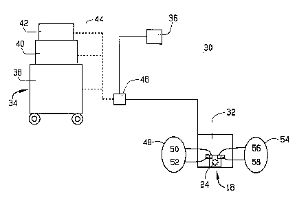
FIG. 3 is an illustration of a ophthalmic surgical system in accordance with
the present invention; and
2

CA 02469900 2004-06-10
WO 03/053293 PCT/US02/39194
FIG. 4 is a block diagram of a switch interloclc circuit in accordance with
one
aspect of the present invention.
Detailed Description of the P~efe~~ed Embodiment:
FIG. 1 shows a foot controller 10, in accordance with the present invention.
Foot controller 10 includes a body portion 12, an accelerator-type pedal 14,
and
control buttons 16. In use, foot controller 10 is typically attached to an
ophthalmic
surgical system, such as the Millennium~ system available from Bausch & Lomb
Inc. (not shown). Foot controller 10 by use of accelerator-type pedal 14 or
switches
16 activates and controls various surgical instruments, as is well-known. In
addition
to the pedal 14 and switches 16, the present invention incorporates a door 18
covering a switch 24 (shown below). The door 18 functions as a heel-rest when
in a
closed position of FIG. l, and as a switch-shroud when in an open position of
FIG.
2. Preferably, door 18 includes a heel-rest ridge 20 for user comfort. In
addition,
door 18 preferably includes a toe-ridge 22 for allowing a surgeon to open door
18
easily. However, it is noted that foot controller 10 may have one or more
doors 18
covering switches 24 and/or 16. It is not necessary that door 18 also be a
heel-rest.
3

CA 02469900 2004-06-10
WO 03/053293 PCT/US02/39194
FIG. 2 shows foot controller 10 with door 18 in an open position. As can be
seen, switch 24 controlling a surgical apparatus, such as a laser, is
effectively
shrouded by door 18, thereby preventing unintended activation of switch 24.
Preferably door 18 is spring-loaded so that the door will automatically close
unless
in an open detented position.
In this way, a surgical switch 24 requiring a shroud is conveniently
incorporated into an otherwise typical foot controller for use in ophthalmic
surgery.
FIG. 3 shows an ophthalmic surgical system 30 consisting of a foot
controller 32, a surgical console 34, and optionally, a satellite foot switch
36.
Surgical console 34 may consist of a cart 38, a base or control unit 40, and
optionally, an expansion unt 42. Foot controller 32 and switch 36, as
indicated by
dashed lines 44, may be coimected to any one of units 38, 40, and 42. Optional
satellite foot switch 36 is shown connected to surgical console 34 via a
common
node 46. It should be appreciated that satellite foot switch 36 is generally
dedicated
to one surgical apparatus, such as a surgical laser and generally, is required
to be
shrouded as discussed above.
In practice, it may be desirable to have such a satellite switch 36 for the
convenience of the surgeon in that, as the surgeon moves about the patient,
switch
36 is more easily moved than main foot controller 32. For the sake of safety,
it may
4

CA 02469900 2004-06-10
WO 03/053293 PCT/US02/39194
be desirable to have an interloclc or safety checks on foot controller 32 to
ensure that
switch 24 is not activated by accident.
To ensure that switch 24 is not accidentally activated on foot controller 32,
it
is desirable to have a door position sensor 48 for disabling activation of the
surgical
switch 24 except when the door 18 is in an open position. Door position sensor
48
may consist of a magnet 50 in combination with a Hall-effect IC 52 to form a
Hall-
effect sensor. Then, when the magnet moves to a position adjacent Hall-effect
IC
52, switch 24 is enabled. For situations in which redundancy is desired, a
door-
presence sensor 54 for detecting when a door is present on a foot controller
may also
be used. Like sensor 48, sensor 54 may consist of a magnet 56 on door 18 and a
Hall-effect IC 58. In much the same way as sensor 48 detects that the door is
in a
proper position, if sensor 54 is used, then the presence of door 18 must be
detected
before switch 24 is enabled. That is to say in such a redundant system,
surgical
switch 24 is disabled except when the door is present and open as detected by
sensors 54 and 48, respectively. Requiring door 18 to be open before switch 24
is
enabled prevents a foreign object being lodged between door 18 and switch 24
from
activating the surgical equipment upon closure of door 18.
In a still further embodiment of the present invention, the satellite switch
36
which is separate from, but electrically connected to, the foot controller 32
may be
enabled by sensors 48 and 54. In such a configuration, satellite 36 is
disabled except

CA 02469900 2004-06-10
WO 03/053293 PCT/US02/39194
when the door 18 is in an open position. Or, in a redundant system, satellite
36 is
disabled except when the door is present and in an open position. Such a
configuration may be highly desirable when console 34 includes a laser
controlled
by switches 24 and/or 36, since the inadvertent operation of switch 24 or
switch 36
could cause serious injury to the patient or others in the operating room.
Various embodiments of an inventive surgical system 30 have been
described. The disablement of foot controller 32, switch 24, and satellite
switch 36
may be made from surgical console 34 with or without the use of sensors 48 and
54.
It is noted that foot controller 32 is essentially identical to foot
controller 10
except that sensors 48 and 54 have been added.
FIG. 4 shows a block diagram of a circuit incorporating cormnercially
available Hall-effect ICs 52 and 58. hi addition to Hall-effect IC 52, sensor
48
includes a switch 60 (in a preferred embodiment switches 60 and 64 combine to
form switch 24) which is connected to a relay 62. Switch 60 is typically
electrically
open and unpowered, unless Hall-effect IC 52 detects the presence of magnet
50, in
which case switch 60 is powered and enabled. In an enabled state, switch 60
then
controls relay 62. Relay 62 then sends an enabling signal to surgical console
34
causing the surgical instrument associated with switch 24 to operate. If
redundancy
6

CA 02469900 2004-06-10
WO 03/053293 PCT/US02/39194
is desired, Hall-effect IC 58 then cooperates with Hall-effect IC 52 to enable
or
disable switch 24 and/or 36.
Switch 64 and relay 66 provide redundancy for switch 60 and relay 62. In a
situation where switch 60 has failed in a powered and enabled position, switch
64
and relay 66 ensure that the surgical instrument attached to switch 24 will
not be
enabled accidentally. In a similar fashion, Hall-effect IC 58 prevents
accidental
operation because of the failure of Hall-effect IC 52. Therefore, only IC 52,
switch
64, and relay 62 are needed for operation of the circuit of FIG. 4. IC 58,
switch 64,
and relay 66 provide a measure of safety redundancy.
7

Representative Drawing
A single figure which represents the drawing illustrating the invention.
Administrative Status

2024-08-01:As part of the Next Generation Patents (NGP) transition, the Canadian Patents Database (CPD) now contains a more detailed Event History, which replicates the Event Log of our new back-office solution.

Please note that "Inactive:" events refers to events no longer in use in our new back-office solution.

For a clearer understanding of the status of the application/patent presented on this page, the site Disclaimer , as well as the definitions for Patent , Event History , Maintenance Fee  and Payment History  should be consulted.

Event History

Description Date
Inactive: Expired (new Act pat) 2022-12-06
Common Representative Appointed 2019-10-30
Inactive: IPC deactivated 2011-07-29
Grant by Issuance 2008-12-02
Inactive: Cover page published 2008-12-01
Pre-grant 2008-09-18
Inactive: Final fee received 2008-09-18
Notice of Allowance is Issued 2008-04-02
Letter Sent 2008-04-02
Notice of Allowance is Issued 2008-04-02
Inactive: IPC assigned 2008-04-01
Inactive: IPC expired 2008-04-01
Inactive: IPC removed 2008-03-27
Inactive: Approved for allowance (AFA) 2007-12-12
Amendment Received - Voluntary Amendment 2007-10-18
Inactive: S.30(2) Rules - Examiner requisition 2007-06-21
Amendment Received - Voluntary Amendment 2006-08-25
Letter Sent 2006-03-13
Inactive: Office letter 2006-03-13
Inactive: IPC from MCD 2006-03-12
Inactive: Inventor deleted 2006-03-03
Inactive: S.30(2) Rules - Examiner requisition 2006-02-28
Inactive: Delete abandonment 2005-10-27
Inactive: Abandoned - No reply to Office letter 2005-09-13
Correct Applicant Request Received 2005-09-12
Inactive: Single transfer 2005-09-12
Inactive: Cover page published 2004-08-20
Inactive: Courtesy letter - Evidence 2004-08-17
Inactive: Acknowledgment of national entry - RFE 2004-08-16
Letter Sent 2004-08-16
Application Received - PCT 2004-07-09
National Entry Requirements Determined Compliant 2004-06-10
Request for Examination Requirements Determined Compliant 2004-06-10
All Requirements for Examination Determined Compliant 2004-06-10
National Entry Requirements Determined Compliant 2004-06-10
Application Published (Open to Public Inspection) 2003-07-03

Abandonment History

There is no abandonment history.

Maintenance Fee

The last payment was received on 2008-10-02

Note : If the full payment has not been received on or before the date indicated, a further fee may be required which may be one of the following

  • the reinstatement fee;
  • the late payment fee; or
  • additional fee to reverse deemed expiry.

Patent fees are adjusted on the 1st of January every year. The amounts above are the current amounts if received by December 31 of the current year.
Please refer to the CIPO Patent Fees web page to see all current fee amounts.

Owners on Record

Note: Records showing the ownership history in alphabetical order.

Current Owners on Record
BAUSCH & LOMB INCORPORATED
Past Owners on Record
MICHAEL E. METZLER
ROBERT ALLYN
WILLIAM J. NEUBERT
Past Owners that do not appear in the "Owners on Record" listing will appear in other documentation within the application.
Documents

To view selected files, please enter reCAPTCHA code :


To view images, click a link in the Document Description column. To download the documents, select one or more checkboxes in the first column and then click the "Download Selected in PDF format (Zip Archive)" or the "Download Selected as Single PDF" button.

List of published and non-published patent-specific documents on the CPD .

If you have any difficulty accessing content, you can call the Client Service Centre at 1-866-997-1936 or send them an e-mail at CIPO Client Service Centre.


Document
Description 
Date
(yyyy-mm-dd) 
Number of pages   Size of Image (KB) 
Description 2004-06-09 7 214
Claims 2004-06-09 4 86
Drawings 2004-06-09 2 33
Abstract 2004-06-09 1 50
Representative drawing 2004-08-18 1 5
Claims 2006-08-24 4 100
Acknowledgement of Request for Examination 2004-08-15 1 177
Reminder of maintenance fee due 2004-08-15 1 110
Notice of National Entry 2004-08-15 1 202
Request for evidence or missing transfer 2005-06-12 1 101
Courtesy - Certificate of registration (related document(s)) 2006-03-12 1 105
Commissioner's Notice - Application Found Allowable 2008-04-01 1 164
PCT 2004-06-09 6 187
Correspondence 2004-08-15 1 26
Correspondence 2005-09-11 3 125
Correspondence 2006-03-12 1 12
Correspondence 2008-09-17 1 43