Language selection

Search

Patent 2470349 Summary

Third-party information liability

Some of the information on this Web page has been provided by external sources. The Government of Canada is not responsible for the accuracy, reliability or currency of the information supplied by external sources. Users wishing to rely upon this information should consult directly with the source of the information. Content provided by external sources is not subject to official languages, privacy and accessibility requirements.

Claims and Abstract availability

Any discrepancies in the text and image of the Claims and Abstract are due to differing posting times. Text of the Claims and Abstract are posted:

  • At the time the application is open to public inspection;
  • At the time of issue of the patent (grant).
(12) Patent Application: (11) CA 2470349
(54) English Title: TRACTION DRIVE
(54) French Title: ENTRAINEMENT DE TRACTION
Status: Deemed Abandoned and Beyond the Period of Reinstatement - Pending Response to Notice of Disregarded Communication
Bibliographic Data
(51) International Patent Classification (IPC):
  • H02P 6/24 (2006.01)
  • B60L 7/02 (2006.01)
(72) Inventors :
  • JOECKEL, ANDREAS (Germany)
(73) Owners :
  • SIEMENS AKTIENGESELLSCHAFT
(71) Applicants :
  • SIEMENS AKTIENGESELLSCHAFT (Germany)
(74) Agent: SMART & BIGGAR LP
(74) Associate agent:
(45) Issued:
(86) PCT Filing Date: 2002-11-28
(87) Open to Public Inspection: 2003-06-19
Examination requested: 2004-06-09
Availability of licence: N/A
Dedicated to the Public: N/A
(25) Language of filing: English

Patent Cooperation Treaty (PCT): Yes
(86) PCT Filing Number: PCT/DE2002/004380
(87) International Publication Number: WO 2003050940
(85) National Entry: 2004-06-09

(30) Application Priority Data:
Application No. Country/Territory Date
101 60 612.5 (Germany) 2001-12-11

Abstracts

English Abstract


The invention relates to a traction drive comprising a traction power
converter (4) and a permanent-field synchronous motor (6), said traction power
converter (4) comprising at least one pulsed power converter (22) on the
machine side. According to the invention, the permanent-field synchronous
motor (6) is respectively connected to an input of a commutator (30) on the
terminal side, the outputs of said commutator being respectively connected to
an output of the pulsed power converter (22) and to a connection of the star-
connected braking resistances (28). In this way, a fail-safe electrical brake
which is independent from the power inverter can be obtained for a set of
traction wheels of a rail vehicle, such that a mechanical brake is not
required.


French Abstract

L'invention concerne un entraînement de traction comportant un convertisseur de courant statique de traction (4) et un moteur synchrone à excitation permanente (6), ledit convertisseur de courant statique de traction (4) présentant côté machine au moins un convertisseur de courant pulsé (22). Selon l'invention, le moteur synchrone à excitation permanente (6) est raccordé côté bornes à une entrée d'un commutateur (30) dont les sorties sont raccordées respectivement à une sortie du convertisseur de courant pulsé (22) et à une borne de résistances de freinage (28) montées en étoile. Ainsi, il est possible de mettre en oeuvre un frein électrique fiable indépendant de l'onduleur, destiné à un essieu moteur d'un véhicule sur rails, de façon à s'affranchir totalement d'un frein mécanique.

Claims

Note: Claims are shown in the official language in which they were submitted.

Claims
1. Traction drive with a traction converter (4) and a permanent-excited
synchronous motor (6), whereby the traction converter (4) includes at least
one machine-side pulsed inverter (22), characterized in that the terminals
of the permanent-excited synchronous motor (6) are each connected with a
corresponding input of a cross-over switch (30), that the two output
terminals of each cross-over switch (30) are connected, on one hand, with
an output terminal of the pulsed inverter (22) and, on the other hand, with a
terminal of a brake resistor (28), and that the brake resistors (28) are
electrically connected in a star configuration.
2. Traction drive according to claim 1, characterized in that the brake
resistor
(28) is a constant ohmic resistor.
3. Traction drive according to one of the preceding claims, characterized in
that each cross-over switch (30) can be electrically operated.
4. Traction drive according to one of the claims 1 or 2, characterized in that
each cross-over switch (30) can be mechanically operated.
5. Traction drive according to one of the claims 1 or 2, characterized in that
each cross-over switch (30) can be pneumatically operated.
8

6. Traction drive according to one of the preceding claims, characterized in
that the permanent-excited synchronous motor (6) has a synchronous
inductance which is dimensioned so that a short-circuit current is
approximately equal to a rated current.
7. Traction drive according to claim 6, characterized in that the permanent
excited synchronous motor (6) includes magnets arranged in its interior.
8. Traction drive according to one of the preceding claims, characterized in
that the traction converter (4) includes at least one four-quadrant control
element (14), a capacitor battery (18) and a traction transformer (2), that
the
input of each four-quadrant controller (14) is connected with a secondary
winding (12) of the traction transformer (2), and that the DC-sides of these
four-quadrant control elements (14) are connected by the capacitor
battery (18) and the DC terminals of the pulsed inverter (22).
9. Traction drive according to one of the claims 1 to 7, characterized in that
the traction converter (4) includes a capacitor battery (18) and a DC
choke (32), that the capacitor battery (18) is connected electrically in
parallel
with the DC terminals of the pulsed inverter (22), and that the DC choke (32)
connects an input of the traction converter (4) with the positive terminal of
the capacitor battery (18).
9

10. Traction drive according to claim 8, characterized in that a series-
resonant
circuit (16) is electrically connected in parallel with the capacitor battery
(18).
11. Traction drive according to claim 8 or 9, characterized in that an
overvoltage protection device (20) is electrically connected in parallel with
the capacitor battery (18).
10

Description

Note: Descriptions are shown in the official language in which they were submitted.


CA 02470349 2004-06-09
Specification
TRACTION DRIVE
The invention relates to a traction drive according to the preamble of claim
1.
Conventional powered bogies of rail vehicles include asynchronous drive motors
powered by pulsed inverters. These traction drives can also be operated as a
generator brake during the travel and braking mode. A bogie must have a
reliable fail-safe brake so that the powered car can maintain the approved
braking distance even if the pulsed inverter malfunctions. Examples of fail-
safe
brakes are mechanical brakes, for example, disk brakes, shoe brakes andlor
electromagnetic rail brakes.
The brake system of an ICE 212 train set is described in section 4.3 of the
publication "Neue IntercityExpress Triebzuge fur die deutsche Bahn" (New
Intercity-Express-Trains for the German Railways), printed in the German-
language publication "eb - Elektrische Bahnen", Vol. 93, 1995, Nv.1/2, pp. 15
to
24,. Such train sets have, in addition to the generator brake of the three-
phase
z0 asynchronous drive with power line return feed, an air disk brake in both
the
powered bogies and the carrying bogies. The brake disks are implemented as
axle-mounted brake disks in the carrying bogies, whereas wheel brake disks in
the powered bogies have sintered brake pads. The electronic brake control is
1

CA 02470349 2004-06-09
combined with the electro-pneumatic control, so that the speed does not have
to
be restricted if the electronics fails. Preferably, the generator brakes ace
activated first, and only afterwards are the mechanical brakes activated.
These mechanical brakes have the following disadvantages:
- a very complex system prone to malfunction,
- a high cost,
- the brake itself requires frequent maintenance, and
- a malfunction in the anti-skid protection immediately causes flat spots on
the
wheel sets, and consequently significant expenses associated with reprofiling
the wheels.
The European patent 0 704 961 describes a device for braking a permanent-
excited synchronous motor of a lift, wherein the stator windings can be
connected with brake resistors via a switch. A frequency converter is provided
for supplying power tv the stator winding of the permanent-excited synchronous
motor. Due to the small synchronous inductance, each of the add-on brake
resistors must have a nonlinear resistance value, which increases with
increasing
voltage. This nonlinear resistor ensures the smallest possible deceleration
rate.
The braking power and the current flowing through the brake resistor become
large when the stator windings of the permanent-excited synchronous motor
supply current through the brake resistors and the motor operates at a very
high-
speed.
2

CA 02470349 2004-06-09
1t is therefore an object of the invention to provide a powered bogie of a
rail
vehicle which does not require any mechanical brake.
This object is solved by the invention with the characterizing feature of
claim 1 in
conjunction with the features of the preamble.
By providing a traction drive according to the invention with a permanent-
excited
synchronous motor instead of an asynchronous motor, brake resistors can now
be used instead of a mechanical brake, which are, on one hand, connected in a
t0 star configuration and which, on the other hand, can be connected with the
stator
windings of the permanent-excited synchronous machine in such a way that the
brake resistors are decoupled from the output terminals of the traction
converter.
The use of a permanent excited synchronous motor does not only eliminate a
gear, but a voltage is present at the terminals of the synchronous motor as
soon
as the motor rotates. This voltage is used to brake a powered bogie of a rail
vehicle. This voltage is switched to the brake resistors by a change-over
switch.
This approach entirely obviates the need for providing a mechanical brake on a
z0 powered bogie of a rail vehicle. Consequently, the costs associated with
maintaining a mechanical brake are also eliminated. Since a mechanical brake
is the longer required, a powered bogie is not only less costly, but also has
a
reduced mass.
3

CA 02470349 2004-06-09
Advantages embodiments of the traction drive are recited in the dependent
claims 2 to 7.
The invention is described in more detail with reference to the drawing which
schematically illustrates two embodiments of a traction drive according to the
invention.
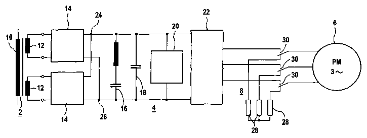
FIG. 1 shows a traction drive according to the invention for an AC-
vehicle, and
FIG. 2 shows a traction drive according to the invention for a DC-
vehicle.
FIG. 1 shows in more detail a traction drive for a vehicle powered by
alternating
1 S current, also referred to as AC-vehicle, whereby the reference numeral 2
refers
to a traction transformer, the reference numeral 4 to a traction converter,
the
reference numeral 6 to a permanent-excited synchronous motor, and the
reference numeral 8 a braking system. The traction transformer 2 has a primary
winding 10 and several secondary windings 12, with only two of the secondary
windings 12 shown in FIG. 1. The traction converter 4 has two four-quadrant
control elements 14, a series-resonant circuit 16, a capacitor battery 18, an
overvoltage protection device 20 and a pulsed inverter 22 on the machine side.
The AC terminals of the two four-quadrant controllers 14 are each connected
4

CA 02470349 2004-06-09
with a corresponding secondary winding 12 of the traction transformer 2,
whereas the DC terminals are electrically connected in parallel. The series-
resonant circuit 16, the capacitor battery 18, the overvoltage protection
device 20
and the DC-side input terminals of the machine-side pulsed inverter 22 are
connected in parallel with the two DC-side terminals 24 and 26 of this supply
circuit. The output terminals of the machine-side pulsed inverter 22 can be
connected with terminals of the permanent-excited synchronous motor 6. Such
traction drive is known in the art.
The braking system 8 includes a brake resistor 28 and a cross-over switch 30
for
each phase of the permanent-excited synchronous motor 6. The brake
resistors 28 are electrically connected in a star configuration and have each
a
constant resistance value. The cross-over switches 30 are connected with the
output terminals of the machine-side pulsed inverter 22 and with the input
terminals of the permanent-excited synchronous motor 6 in such a way, that the
input terminals of the permanent~excited synchronous motor 6 can be connected,
on one hand, with the brake resistor 213 and, on the other hand, with the
output
terminals of the machine-side pulsed inverter 2.
These cross-over switches 28, which are also referred to as fail-safe
switches,
can be operated electrically or mechanically or pneumatically. The permanent-
excited synchronous motor 6 generates a braking torque that decreases with a
decrease in the speed of the rail vehicle as soon as these cross-over switches
28
5

CA 02470349 2004-06-09
are switched from the operating position "Drive", where the terminals of the
permanent-excited synchronous motor are connected with the output terminals of
the machine-side pulsed inverter 22, into the operating position "Braking",
where
the terminals of the permanent-excited synchronous motor 6 are connected with
the brake resistors 28 that are connected in a star configuration. Neither the
machine-side pulsed inverter 22 nor any other control elements are required
for
generating the braking torque.
This approach results in a fail-safe electric brake for a powered bogie of a
rail
vehicle that operates independent of fihe inverter.
The fail-safe brake has also an inherent anti-skid protection. In other words,
braking can no longer cause flat spots of the wheel set of a powered bogie,
since
the generated braking torque decreases automatically when the wheel set begins
to skid on a wet rail. A prerequisite for generating the braking torque is a
rotation
of the rotor of the permanent-excited synchronous motor. Without a rotation of
the rotor, no voltage is generated at the terminals of the permanent-excited
synchronous motor. The brake resistors 28 cannot generate a braking torque
without an induced voltage. When the wheels of a wheel set of a rail vehicle
skid, the wheels are almost at rest_ In this situation, the pemnanent-excited
synchronous motor 6 and the brake resistors 28 cannot generate a braking
torque for the skidding wheels, so that flat spots are no longer produced.
6

CA 02470349 2004-06-09
With the embodiment of the traction drive according to the invention, a
mechanical brake can be entirely eliminated on a drive wheel set of a rail
vehicle.
FIG. 2 shows in more detail a traction drive for a vehicle powered by direct
current, also referred to as DC-vehicle. This traction drive, unlike the
traction
drive of FIG. 1, has a traction converter 4 that includes neither four-
quadrant
control elements 14 nor a traction transformer Z or a series-resonant circuit
16.
The capacitor battery 18 is here electrically connected via a DC choke 32 with
a
pantograph of the DC-vehicle. Depending on the contact wire voltage, the
traction converter 4 can include a DCIDC converter, in particular if the DC-
vehicle
is to be operated of several different DC voltage systems. A DCIDC converter
of
this type would be implemented as a step-uplstep-down switching regulator.
As seen from the two exemplary embodimenfis of a traction drive, it is
unimportant for the implementation of the traction drive according to the
invention
how the power supply circuit is configured. However, the motor must be a
permanent-excited synchronous motor which is powered by a pulsed inverter 22.
Accordingly, a traction drive for a diesel-electric vehicle can also be
implemented
according to the invention.
7

Representative Drawing
A single figure which represents the drawing illustrating the invention.
Administrative Status

2024-08-01:As part of the Next Generation Patents (NGP) transition, the Canadian Patents Database (CPD) now contains a more detailed Event History, which replicates the Event Log of our new back-office solution.

Please note that "Inactive:" events refers to events no longer in use in our new back-office solution.

For a clearer understanding of the status of the application/patent presented on this page, the site Disclaimer , as well as the definitions for Patent , Event History , Maintenance Fee  and Payment History  should be consulted.

Event History

Description Date
Application Not Reinstated by Deadline 2009-04-27
Inactive: Dead - No reply to s.30(2) Rules requisition 2009-04-27
Deemed Abandoned - Failure to Respond to Maintenance Fee Notice 2008-11-28
Inactive: Abandoned - No reply to s.30(2) Rules requisition 2008-04-25
Inactive: S.30(2) Rules - Examiner requisition 2007-10-25
Letter Sent 2004-09-28
Inactive: Courtesy letter - Evidence 2004-09-21
Inactive: Cover page published 2004-09-21
Letter Sent 2004-09-17
Inactive: Acknowledgment of national entry - RFE 2004-09-17
Application Received - PCT 2004-07-14
Inactive: Single transfer 2004-06-23
Request for Examination Requirements Determined Compliant 2004-06-09
All Requirements for Examination Determined Compliant 2004-06-09
National Entry Requirements Determined Compliant 2004-06-09
Application Published (Open to Public Inspection) 2003-06-19

Abandonment History

Abandonment Date Reason Reinstatement Date
2008-11-28

Maintenance Fee

The last payment was received on 2007-10-16

Note : If the full payment has not been received on or before the date indicated, a further fee may be required which may be one of the following

  • the reinstatement fee;
  • the late payment fee; or
  • additional fee to reverse deemed expiry.

Please refer to the CIPO Patent Fees web page to see all current fee amounts.

Fee History

Fee Type Anniversary Year Due Date Paid Date
Basic national fee - standard 2004-06-09
Request for examination - standard 2004-06-09
Registration of a document 2004-06-23
MF (application, 2nd anniv.) - standard 02 2004-11-29 2004-10-18
MF (application, 3rd anniv.) - standard 03 2005-11-28 2005-10-14
MF (application, 4th anniv.) - standard 04 2006-11-28 2006-10-13
MF (application, 5th anniv.) - standard 05 2007-11-28 2007-10-16
Owners on Record

Note: Records showing the ownership history in alphabetical order.

Current Owners on Record
SIEMENS AKTIENGESELLSCHAFT
Past Owners on Record
ANDREAS JOECKEL
Past Owners that do not appear in the "Owners on Record" listing will appear in other documentation within the application.
Documents

To view selected files, please enter reCAPTCHA code :


To view images, click a link in the Document Description column. To download the documents, select one or more checkboxes in the first column and then click the "Download Selected in PDF format (Zip Archive)" or the "Download Selected as Single PDF" button.

List of published and non-published patent-specific documents on the CPD .

If you have any difficulty accessing content, you can call the Client Service Centre at 1-866-997-1936 or send them an e-mail at CIPO Client Service Centre.


Document
Description 
Date
(yyyy-mm-dd) 
Number of pages   Size of Image (KB) 
Abstract 2004-06-09 1 21
Description 2004-06-09 7 251
Claims 2004-06-09 3 75
Representative drawing 2004-06-09 1 8
Drawings 2004-06-09 2 20
Cover Page 2004-09-21 1 37
Acknowledgement of Request for Examination 2004-09-17 1 185
Reminder of maintenance fee due 2004-09-20 1 110
Notice of National Entry 2004-09-17 1 225
Courtesy - Certificate of registration (related document(s)) 2004-09-28 1 129
Courtesy - Abandonment Letter (R30(2)) 2008-08-18 1 165
Courtesy - Abandonment Letter (Maintenance Fee) 2009-01-26 1 174
PCT 2004-06-09 6 221
Correspondence 2004-09-17 1 25