Language selection

Search

Patent 2470538 Summary

Third-party information liability

Some of the information on this Web page has been provided by external sources. The Government of Canada is not responsible for the accuracy, reliability or currency of the information supplied by external sources. Users wishing to rely upon this information should consult directly with the source of the information. Content provided by external sources is not subject to official languages, privacy and accessibility requirements.

Claims and Abstract availability

Any discrepancies in the text and image of the Claims and Abstract are due to differing posting times. Text of the Claims and Abstract are posted:

  • At the time the application is open to public inspection;
  • At the time of issue of the patent (grant).
(12) Patent Application: (11) CA 2470538
(54) English Title: TRUCK BED LINING
(54) French Title: GARNITURE DE CAISSE DE CAMION
Status: Deemed Abandoned and Beyond the Period of Reinstatement - Pending Response to Notice of Disregarded Communication
Bibliographic Data
(51) International Patent Classification (IPC):
  • B62D 25/20 (2006.01)
  • B32B 25/00 (2006.01)
  • B60R 13/01 (2006.01)
  • E04F 15/10 (2006.01)
(72) Inventors :
  • MARQUETTE, DANY (Canada)
(73) Owners :
  • DANY MARQUETTE
(71) Applicants :
  • DANY MARQUETTE (Canada)
(74) Agent:
(74) Associate agent:
(45) Issued:
(22) Filed Date: 2004-06-09
(41) Open to Public Inspection: 2005-12-09
Availability of licence: N/A
Dedicated to the Public: N/A
(25) Language of filing: English

Patent Cooperation Treaty (PCT): No

(30) Application Priority Data: None

Abstracts

Sorry, the abstracts for patent document number 2470538 were not found.

Claims

Note: Claims are shown in the official language in which they were submitted.
Sorry, the claims for patent document number 2470538 were not found.
Text is not available for all patent documents. The current dates of coverage are on the Currency of Information  page

Description

Note: Descriptions are shown in the official language in which they were submitted.


CA 02470538 2004-06-09
TRUCK BED LINING
The present invention relates to vehicles and more particularly, relates to
the floor of
vehicles, preferably those vehicles generally classified as trucks.
The floor structure of those vehicles generally classified as trucks will vary
depending upon the end use of the truck and the material which it will
transport. Generally,
there is provided a frame structure which carries or supports a floor which is
usually formed
of a metallic or wood material. However, is it also known in the art to use
various types of
plastic. It is also known in the art to provide inserts or liners which will
sit on the original
floor provided by the manufacturer of the vehicle.
An example of the above and the problems which can be encountered are trucks
which are used to transport cases of beverages from the manufacturer to the
retail outlet. A
problem which occurs is the movement of the cases or pallets on which the
goods are
shipped during the transport. Any such breakage inherently carries a
substantial economic
cost, both from material loss and in terms of labour.
A problem also exists with respect to damage which can occur to the floor from
impact. In the case of the vehicles having a wood floor, the wood frequently
breaks and
must be replaced. Even in the case of metallic floors, impact can deform and
even fracture
the metal thereby necessitating replacement.
When carrying goods, the goods are usually secured in place by means of
various
types of straps. However, any slight loosening of the straps will mean that
the cargo is able
to move.
It is therefore an object of the present invention to provide a floor
structure which
overcomes the above problems.

CA 02470538 2004-06-09
According to the present invention, there is provided a floor structure for a
truck or a
like vehicle, the floor structure comprising a frame, a floor mounted on the
frame, the floor
member being substantially planar, and a rubber layer, the rubber layer being
adhesively
secured to the floor.
In greater detail, the present invention utilises a rubber floor or layer
which has
specific properties and which is designed to provide a surface which is slip
resistant and
slightly flexible for reasons which will become apparent hereinbelow, and
which is suitable
for many different types of uses. The rubber layer is preferably formed of
particles of
recycled rubber from various sources such as vehicle tires and the like. The
rubber layer
preferably has a thickness of between approximately 68 and 72 as measured on a
Shore
hardness meter under ASTM D-2240. It will preferably have a coefficient of
friction of
between .80 and .85 as measured by ASTM D-1894 and the specific gravity will
preferably
be between 1.12 and 1.16.
Preferably, the upper surface of the rubber layer is provided with an embossed
outline
to better provide anti-slip capabilities. The underside may conveniently
contain channels
formed therein.
The rubber layer will be adhered to the floor substrate by means of an
adhesive. A
preferred adhesive would be a solvent free two component polyurethane adhesive
such as is
known in the art.
The flooring substrate to which the rubber layer is adhered may be either
metallic or
wood. A preferred material is a metallic one which may be either of steel or
aluminum.
The present invention also includes a method for the manufacture of the floor.
According to the present invention, one provides a metallic floor which is
subjected to a
-2-

CA 02470538 2004-06-09
cleaning to ensure that all foreign substances are removed. The rubber layer
has a bottom
portion thereof removed. Subsequently, an adhesive is placed either on at
least one of the
metallic layer and/or rubber layer and the two are adhesively secured
together. A pressure is
maintained on the materials to ensure proper bonding.
Having thus generally described the invention, reference will be made to the
accompanying drawings illustrating an embodiment thereof, in which:
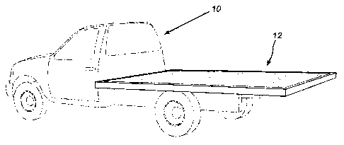
Figure 1 is a perspective view illustrating a vehicle (in phantom lines) and
having a
floor structure;
Figure 2 is a top end view, partially in cut away, of the floor structure of
the vehicle
of Figure 1;
Figure 3 is a cross sectional view taken along the lines 3 - 3 of Figure 2;
Figure 4 is a cross sectional view taken along the lines 4 - 4 of Figure 2;
and
Figure 5 is an enlarged view of the corner portion of the floor structure.
Referring to the drawings in greater detail and by reference characters
thereto, there
is illustrated in Figure 1 a truck which is generally designated by reference
numeral 10 and
which has a floor structure generally designated by reference numeral 12.
Floor structure 12 comprises a plurality of transversely extending C-shaped
frame
members 14. Extending around the outer edge are provided inverted L-shaped
frame
members 16.
Mounted to the under side of inverted L-shaped frame members 16 is a bottom
layer
18 while on top of inverted L-shaped frame members 16 there is provided a top
layer 20.
Top layer 20, in the illustrated embodiments of Figures 1 to 4, comprises a
thin metallic
layer either of stainless steel or aluminum and preferably being of a
thickness of
-3-

CA 02470538 2004-06-09
approximately 1/8 inch.
A rubber layer 22, which is of a composition as previously set forth
hereinabove, is
secured to top layer 20 by means of an adhesive layer 24. There may be
provided a plurality
of reinforcement members 26.
In the embodiment of Figure 5, there is provided a top layer 20' which is
formed of a
hardwood material, preferably between 1 and 1 %z inches thick.
In this regards, layer 20' can be formed of a suitable composite materials and
manufactured material as desired.
In the bottom of rubber layer 22, there are provided a plurality of grooves
28.
It will be understood that the above described embodiment is for purposes of
illustration only and the changes and modifications may be made thereto
without departing
from the spirit and scope of the invention.
-4-

Representative Drawing
A single figure which represents the drawing illustrating the invention.
Administrative Status

2024-08-01:As part of the Next Generation Patents (NGP) transition, the Canadian Patents Database (CPD) now contains a more detailed Event History, which replicates the Event Log of our new back-office solution.

Please note that "Inactive:" events refers to events no longer in use in our new back-office solution.

For a clearer understanding of the status of the application/patent presented on this page, the site Disclaimer , as well as the definitions for Patent , Event History , Maintenance Fee  and Payment History  should be consulted.

Event History

Description Date
Revocation of Agent Requirements Determined Compliant 2021-04-01
Inactive: IPC assigned 2019-02-20
Inactive: IPC removed 2019-02-20
Inactive: IPC expired 2019-01-01
Inactive: IPC removed 2018-12-31
Application Not Reinstated by Deadline 2007-06-11
Time Limit for Reversal Expired 2007-06-11
Deemed Abandoned - Failure to Respond to Notice Requiring a Translation 2006-12-27
Inactive: Incomplete 2006-09-26
Deemed Abandoned - Failure to Respond to Maintenance Fee Notice 2006-06-09
Application Published (Open to Public Inspection) 2005-12-09
Inactive: Cover page published 2005-12-08
Inactive: IPC assigned 2005-06-22
Inactive: IPC assigned 2004-11-22
Inactive: First IPC assigned 2004-11-22
Inactive: Filing certificate - No RFE (English) 2004-07-15
Filing Requirements Determined Compliant 2004-07-15
Application Received - Regular National 2004-07-15

Abandonment History

Abandonment Date Reason Reinstatement Date
2006-12-27
2006-06-09

Fee History

Fee Type Anniversary Year Due Date Paid Date
Application fee - small 2004-06-09
Owners on Record

Note: Records showing the ownership history in alphabetical order.

Current Owners on Record
DANY MARQUETTE
Past Owners on Record
None
Past Owners that do not appear in the "Owners on Record" listing will appear in other documentation within the application.
Documents

To view selected files, please enter reCAPTCHA code :


To view images, click a link in the Document Description column. To download the documents, select one or more checkboxes in the first column and then click the "Download Selected in PDF format (Zip Archive)" or the "Download Selected as Single PDF" button.

List of published and non-published patent-specific documents on the CPD .

If you have any difficulty accessing content, you can call the Client Service Centre at 1-866-997-1936 or send them an e-mail at CIPO Client Service Centre.


Document
Description 
Date
(yyyy-mm-dd) 
Number of pages   Size of Image (KB) 
Abstract 2005-12-09 1 2
Claims 2005-12-09 1 2
Description 2004-06-09 4 155
Drawings 2004-06-09 2 53
Representative drawing 2005-11-14 1 8
Cover Page 2005-11-18 1 24
Filing Certificate (English) 2004-07-15 1 158
Reminder of maintenance fee due 2006-02-13 1 110
Courtesy - Abandonment Letter (Maintenance Fee) 2006-08-07 1 175
Courtesy - Abandonment Letter (incomplete) 2007-01-17 1 165
Correspondence 2004-07-15 1 13
Correspondence 2006-09-20 1 18