Language selection

Search

Patent 2472229 Summary

Third-party information liability

Some of the information on this Web page has been provided by external sources. The Government of Canada is not responsible for the accuracy, reliability or currency of the information supplied by external sources. Users wishing to rely upon this information should consult directly with the source of the information. Content provided by external sources is not subject to official languages, privacy and accessibility requirements.

Claims and Abstract availability

Any discrepancies in the text and image of the Claims and Abstract are due to differing posting times. Text of the Claims and Abstract are posted:

  • At the time the application is open to public inspection;
  • At the time of issue of the patent (grant).
(12) Patent Application: (11) CA 2472229
(54) English Title: ROTOR OF A PERMANENT-MAGNET MOTOR AND CORRESPONDING MANUFACTURING METHOD
(54) French Title: ROTOR D'UN MOTEUR A AIMANTS PERMANENTS ET PROCEDE DE FABRICATION CORRESPONDANT
Status: Deemed Abandoned and Beyond the Period of Reinstatement - Pending Response to Notice of Disregarded Communication
Bibliographic Data
(51) International Patent Classification (IPC):
  • H02K 15/03 (2006.01)
  • F04D 25/06 (2006.01)
  • H02K 7/14 (2006.01)
(72) Inventors :
  • KOHONEN, REIJO (Finland)
  • HYVAERINEN, JUHANI (Finland)
  • IKONEN, ILKKA T. (Finland)
  • WAINIO, SAMI (Finland)
  • POEYHOENEN, MATTI (Finland)
  • MOEKSY, JUHANI (Finland)
  • RINTA-VALKAMA, JORMA (Finland)
  • FORSMAN, KIMMO (Finland)
  • RYDHOLM, BENGT (Sweden)
(73) Owners :
  • FLAKT WOODS AB
(71) Applicants :
  • FLAKT WOODS AB (Sweden)
(74) Agent: ROBIC AGENCE PI S.E.C./ROBIC IP AGENCY LP
(74) Associate agent:
(45) Issued:
(86) PCT Filing Date: 2003-03-05
(87) Open to Public Inspection: 2003-09-12
Availability of licence: N/A
Dedicated to the Public: N/A
(25) Language of filing: English

Patent Cooperation Treaty (PCT): Yes
(86) PCT Filing Number: PCT/FI2003/000163
(87) International Publication Number: WO 2003075498
(85) National Entry: 2004-06-30

(30) Application Priority Data:
Application No. Country/Territory Date
20020438 (Finland) 2002-03-07

Abstracts

English Abstract


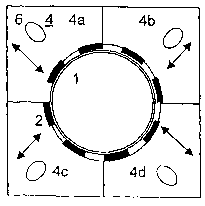
A method for making a rotating part of plastic material for a permanent magnet
motor and a rotor arranged on the outer circumference of the rotating part,
said rotor comprising an annular part (1) and a permanent magnet unit fitted
around it, in which method the rotating part is cast in a mold tool (4). The
annular part (1) together with the permanent magnets (2) is placed inside a
plastic injection mold tool (4), said plastic injection mold tool (4) being
divided radially into several sectors (4a-4d) which are provided with slots
(6) allowing them to be moved radially by an actuator. When the plastic
injection mold tool (4) is being closed, the sector are tightened radially
inwards, specifically closing the air gap between the outer surface of the
permanent magnet unit (2) and the sectors of the plastic injection mold tool
(4), whereupon plastic injection molding is performed.


French Abstract

L'invention concerne un procédé de fabrication d'une partie rotative en plastique destinée à un moteur à aimants permanents et un rotor disposé sur la circonférence extérieure de la partie rotative, ledit rotor comprenant une partie annulaire (1) et une unité d'aimants permanents ajustée autour de la partie annulaire. Dans ce procédé, la partie rotative est fondue dans un moule (4). La partie annulaire (1) et les aimants permanents (2) sont placés à l'intérieur du moule d'injection de matières plastiques (4), lequel est divisé radialement en plusieurs secteurs (4a-4d) munis de fentes (6) qui leur permettent de se déplacer radialement au moyen d'un dispositif de commande. Lorsque le moule d'injection de matières plastiques (4) est fermé, les secteurs se resserrent dans une direction radiale intérieure, fermant de manière spécifique la couche d'air qui sépare la surface extérieure de l'unité d'aimants permanents (2) et les secteurs du moule d'injection de matières plastiques (4), ce qui permet d'accomplir le moulage par injection de matières plastiques.

Claims

Note: Claims are shown in the official language in which they were submitted.

5
CLAIMS
1. Rotor arranged on the outer circumference of the rotating part (14) of a
per-
manent magnet motor, said rotor comprising an annular part (1,11) and a per-
manent magnet unit fitted around it, characterized in that the annular part is
made of band-like material.
2. Rotor according to claim 1, characterized in that the band-like material
con-
sists of dynamo sheet band, which forms a dynamo sheet ring.
3. Rotor according to claim 1, characterized in that the permanent magnet unit
is a polarized magnet ring.
4. Method for making a rotating part (14) of plastic material for a permanent
magnet motor and a rotor arranged on the outer circumference of the rotating
part, said rotor comprising an annular part (1) and a permanent magnet unit
fitted around it, in which method the rotating part is cast in a mold tool
(4),
characterized in that
the annular part (1) together with the permanent magnets (2) is placed inside
a
plastic injection mold tool (4), said plastic injection mold tool (4) being
divided
radially into several sectors (4a - 4d) which are provided with slots (6)
allowing
them to be moved radially by an actuator,
and when the plastic injection mold tool (4) is being closed, the sectors are
tightened radially inwards, specifically closing the air gap between the outer
surface of the permanent magnet unit (2) and the sectors of the plastic
injection
mold tool (4),
whereupon plastic injection molding is performed.
5. Method according to claim 4, characterized in that the annular part is
formed
from band-like material, which is wound to a desired thickness and joined to
form a solid ring.
6. Method according to claim 5, characterized in that the band-like material
consists of dynamo sheet band, which forms a dynamo sheet ring.

6
7. Method according to claim 4, characterized in that the permanent magnet
unit is a polarized magnet ring (12), and an inner ring (11) made of band mate-
rial is automatically stretched inside the magnet ring (12).

Description

Note: Descriptions are shown in the official language in which they were submitted.


CA 02472229 2004-06-30
WO 03/075498 PCT/FI03/00163
1
ROTOR OF A PERMANENT-MAGNET MOTOR AND CORRESPONDING
MANUFACTURING METHOD
The present invention relates to a rotor for a permanent-magnet motor as de-
fined in the preamble of claim 1, arranged on the outer circumference of the
rotating part of the motor. The invention also relates to a manufacturing
method.
In prior art, axial fans are known in which the rotor of an electric motor is
inte-
grated with the impeller, the fan and motor having a common frame and hous-
ing, so it is not necessary to provide separate bearings and axles for the fan
and the motor. An axial fan of this type is disclosed e.g. in US patent
specifica-
tion 4,618,806, which comprises a brushless direct-current motor in which an
impeller and a rotor placed on its outer circumference are rotated by a
stator.
The rotor has an annular permanent magnet, which is magnetized in eight dif-
ferent segments. The permanent magnet is attached to a ring on the outer cir-
cumference of the impeller. As the rotor is arranged on the circumference of
the
impeller, the impeller bearing is not unduly heated by the heat generated by
the
electric motor, as it would be if the electric motor were mounted near the
bear-
ing. The placement of the rotor and stator on the circumference eliminates the
2o fast wear caused by bearing currents. In addition, the bearing is thus
potential-
free.
A drawback with prior-art rotors of permanent magnet motors is a relatively
complicated structure and a complicated manufacturing process.
It is an object of the invention to overcome the drawbacks of prior-art and to
produce a new type of rotor arranged on the outer circumference of the
rotating
part of a motor. It is also an object of the invention to create a new type of
method for manufacturing the rotating part of a motor and a rotor arranged on
3o its outer circumference.
In the rotor of the invention for a permanent magnet motor, an inner ring made
from band material, preferably dynamo sheet band is used, on the outside of
which is arranged a permanent magnet part, either in segments that can be se-
cured to the surface of the ring part or as a polarized magnet ring.

CA 02472229 2004-06-30
WO 03/075498 PCT/FI03/00163
2
In the manufacturing method of the invention, a ring part is prepared from dy-
namo sheet band and a permanent magnet part is arranged on its outer cir-
cumference, either in segments that can be secured to the surface of the ring
part or as a polarized~ii-~agnet ring, and the rotor thus formed is tightened
in a
mould so that no plastic will be spread onto the magnets.
The features of the invention are specified in detail in the claims below.
The primary advantage of the invention is that a very simple structure is
1o achieved that is additionally simple to manufacture. Moreover, by applying
the
invention, the rotor/impeller can be balanced in a simple and fast manner.
In the following, the invention will be described in detail with reference to
an ex-
ample and the attached drawings, wherein
Fig. 1 illustrates how a dynamo sheet ring for a rotor arranged on the outer
cir-
cumference of the rotating part of a permanent magnet motor is produced ac-
cording to the invention,
2o Fig. 2 illustrates the gluing/fixing of permanent magnets,
Fig. 3 illustrates how a rotor arranged on the outer circumference of the
rotating
part of a permanent magnet motor is produced according to the invention by
using a plastic injection mold tool, and
Fig. 4a and 4b present a rotor structure according to the invention,
comprising a
multi-pole magnet ring, in front view and in side view.
Fig. 1 - 3 illustrate an arrangement according to the invention for making a
rotor
so for the permanent magnet motor of an axial fan for use e.g. in air
conditioning
systems. In the axial fan of the invention, the stator of the motor is mounted
around the rotor and secured to the housing, and the rotor is integrated with
the
impeller. The fan has a plastic impeller comprising a rotor arranged on its
outer
circumference, a hole for a shaft at its center and impeller vanes arranged -
be-
tween the central part and an outer annular part.

CA 02472229 2004-06-30
WO 03/075498 PCT/FI03/00163
3
In the invention, the rotor of the permanent magnet motor consists of a dynamo
sheet ring 1 and permanent magnet segments 2. The dynamo sheet ring is
made from dynamo sheet band 3, which is wound about to form a ring as illus-
trated in Fig. 1. The dynamo sheet ring 1 controls the direction of the
magnetic
flux. The permanent magnets 2 are glued to the outer surface of the dynamo
sheet ring 1 as illustrated in Fig. 2. The body of the rotor/impeller is
produced by
the plastic injection molding method, e.g. in an automatically calibrated
plastic
injection mold tool 4.
In the invention, the dynamo sheet ring 1 is made from dynamo sheet band 3,
which is wound to a desired thickness and welded/joined to form a solid ring.
The permanent magnets 2 are glued/attached onto the dynamo sheet ring 1 in a
jig in appropriate positions as indicated by the arrows 5. The dynamo sheet
ring
1, together with the glued/attached permanent magnets 2 are placed in correct
positions inside the plastic injection mold tool 4, which has inside it an
opening
4e having a shape corresponding to the shape of the rotor/impeller. The
plastic
injection mold tool 4 is divided in the radial direction of the impeller into
four sec-
tors 4a - 4d, which are provided with slots 6 allowing them to be moved by an
actuator (not shown) in the radial direction of the shape of the impeller mold
as
2o indicated by the arrows. When the plastic injection mold tool 4 is opened,
the
four sectors are automatically moved radially outwards to allow the dynamo
sheet ring to be inserted and the finished p roduct to be removed. When t he
plastic injection mold tool 4 is to be closed, the four sectors are tightened
ra-
dially inwards, thus closing the air gap between the outer surface of the
perma-
nent magnets 2 and the four radially moving sectors of the plastic injection
mold
tool 4. Plastic injection molding can then be carried out. When the sectors
are
being tightened, no plastic can be spread onto the permanent magnet seg-
ments.
so The product is a plastic rotor/impeller which comprises a dynamo sheet ring
1
with permanent magnets 2 as integrated parts and in which the need for balanc-
ing as well as the air gap between the active rotor and stator components have
been minimized.
The multi-pole magnet ring according to the invention may also be implemented
as illustrated in Fig. 4a and 4b. In this embodiment, the stator winding 13 is
fit-
ted in the fan frame 10 and the rotor/impeller 14 is fitted inside it, the ro-

CA 02472229 2004-06-30
WO 03/075498 PCT/FI03/00163
4
tor/impeller comprising a dynamo sheet ring 11 and around it a polarized mag-
net r ing 12, i n w hich the + a nd - p oles a re m agnetized a s r equired. S
uch a
magnet r ing i s a asy t o fit i nto a mold. The i nner r ing 1 1 made from d
ynamo
sheet band is automatically stretched inside the magnet ring 12. It can be
easily
placed in the mold.
The dynamo sheet need not be insulated or directed in the conventional man-
ner, like e.g. transformer sheets.
It is obvious to the person skilled in the art that the embodiments of the
inven-
tion are not limited to the example described above, but that they may instead
be varied within the scope of the claims presented below.

Representative Drawing
A single figure which represents the drawing illustrating the invention.
Administrative Status

2024-08-01:As part of the Next Generation Patents (NGP) transition, the Canadian Patents Database (CPD) now contains a more detailed Event History, which replicates the Event Log of our new back-office solution.

Please note that "Inactive:" events refers to events no longer in use in our new back-office solution.

For a clearer understanding of the status of the application/patent presented on this page, the site Disclaimer , as well as the definitions for Patent , Event History , Maintenance Fee  and Payment History  should be consulted.

Event History

Description Date
Inactive: IPC expired 2022-01-01
Inactive: IPC from MCD 2006-03-12
Application Not Reinstated by Deadline 2006-03-06
Time Limit for Reversal Expired 2006-03-06
Deemed Abandoned - Failure to Respond to Maintenance Fee Notice 2005-03-07
Inactive: Cover page published 2004-09-15
Letter Sent 2004-09-13
Inactive: Notice - National entry - No RFE 2004-09-11
Application Received - PCT 2004-07-30
National Entry Requirements Determined Compliant 2004-06-30
Application Published (Open to Public Inspection) 2003-09-12

Abandonment History

Abandonment Date Reason Reinstatement Date
2005-03-07

Fee History

Fee Type Anniversary Year Due Date Paid Date
Basic national fee - standard 2004-06-30
Registration of a document 2004-06-30
Owners on Record

Note: Records showing the ownership history in alphabetical order.

Current Owners on Record
FLAKT WOODS AB
Past Owners on Record
BENGT RYDHOLM
ILKKA T. IKONEN
JORMA RINTA-VALKAMA
JUHANI HYVAERINEN
JUHANI MOEKSY
KIMMO FORSMAN
MATTI POEYHOENEN
REIJO KOHONEN
SAMI WAINIO
Past Owners that do not appear in the "Owners on Record" listing will appear in other documentation within the application.
Documents

To view selected files, please enter reCAPTCHA code :


To view images, click a link in the Document Description column. To download the documents, select one or more checkboxes in the first column and then click the "Download Selected in PDF format (Zip Archive)" or the "Download Selected as Single PDF" button.

List of published and non-published patent-specific documents on the CPD .

If you have any difficulty accessing content, you can call the Client Service Centre at 1-866-997-1936 or send them an e-mail at CIPO Client Service Centre.


Document
Description 
Date
(yyyy-mm-dd) 
Number of pages   Size of Image (KB) 
Description 2004-06-30 4 186
Drawings 2004-06-30 2 36
Abstract 2004-06-30 1 70
Claims 2004-06-30 2 52
Representative drawing 2004-06-30 1 5
Cover Page 2004-09-15 2 46
Notice of National Entry 2004-09-11 1 201
Courtesy - Certificate of registration (related document(s)) 2004-09-13 1 129
Reminder of maintenance fee due 2004-11-08 1 110
Courtesy - Abandonment Letter (Maintenance Fee) 2005-05-02 1 174
PCT 2004-06-30 2 77