Note: Descriptions are shown in the official language in which they were submitted.
CA 02472501 2004-07-02
WO 03/057282 PCT/US02/41574
SPINAL NEEDLE SYSTEM
BACKGROUND OF THE INVENTION
Field of the Invention
The present invention relates to spinal needles, and in particular,
to an epidural cannula individually and in combination with an epidural stylet
that stabilizes tissue during penetration by the stylet and provides visual
and
tactile indications of contact with and penetration of tissue.
Description of the Related Art
Epidural cannula and spinal needles have been used for a variety
of medical purposes, including extraction of cerebrospinal fluid (CSF) for
laboratory tests and measurements, introduction of contrast or radionucleotide
agents for diagnostic radiological testing, introduction of pharmaceutical
agents
into the subarachnoid space for therapeutic or anesthetic purposes, and
facilitation of catheter placement within the subarachnoid and epidural
spaces.
While useful, spinal needles require extreme care to ensure their"p,roper
~~c ,~,
placement relative to the spinal dura mater and subarachnoid and
epl°dural
spaces.
Known spinal and epidural needles and the techniques of their
placement, whether free hand or monitored radiologically, are associated with
an unacceptably high incidence of complications. Improper placement results
in such commonly encountered complications as post lumbar puncture spinal
headaches, introduction of contrast agents into the subdural space rather than
into the subarachnoid space, misplacement of an epidural catheter into the
subarachnoid space, and epidural vessel hemorrhage, which may contaminate
CSF samples. Such complications may interfere with the completion of reliable
testing of CSF samples and proceeding with diagnostic tests. Misplacement of
catheters relative to the subarachnoid and epidural spaces may also complicate
the interpretation of diagnostic tests. For example, misplacement of the
catheter can result in the introduction of contrast or radionucleotide agents
into
unintended spaces, such as the injection of a contrast agent into the subdural
rather than the subarachnoid space during myelography. Misplacement of the
catheter can also result in the administration of ineffective, toxic, or
lethal
dosages of anesthetic, antibiotic, chemotherapeutic, or other pharmaceutical
or
CA 02472501 2004-07-02
WO 03/057282 PCT/US02/41574
diagnostic agents. Furthermore, post lumbar puncture spinal headaches cause
patients to suffer protracted periods of painful disability.
BRIEF SUMMARY OF THE INVENTION
The embodiments of the invention are directed to a spinal needle
delivery system having a device for grasping tissue that includes a tubular
member, such as a cannula, having at a distal tip an annular surface
surrounding a terminal port, and at least one barb projecting at an angle from
the annular surface of the tubular member; each of the at least one barbs
having a sharp edge configured to grasp the tissue as the tubular member is at
least partially rotated about its longitudinal axis. Ideally, a plurality of
unidirectional barbs are spaced around the annular surface of the tubular
member.
In accordance with another aspect of the invention, an assembly
is provided for tensioning the needle with respect to the cannula and for
signaling in a visual and tactile manner the position of the needle. The
assembly includes a spring-like tensioning member mounted in a housing that
is attached to a proximal end of the cannula and configured to permit limited
movement of a proximal end of the needle therein.
According to another embodiment of the invention, a method of
using a spinal needle delivery system having a cannula with at least one barb
projecting from a distal surface thereof is provided. The method includes:
inserting the cannula through a first layer of tissue; detecting contact of
the
distal surface of the cannula with a second layer of tissue; and rotating the
cannula in a first direction about its longitudinal axis to urge the at least
one
barb into engagement with the second layer of tissue.
BRIEF DESCRIPTION OF THE DRAWINGS
Figure 1 illustrates one embodiment of the invention implemented
as a spinal needle delivery system.
Figure 2A is an end view and Figure 2B is a partial cross-sectional
view of the distal end of the cannula illustrating one embodiment of the
grasping
barbs of the invention that project from the blunt annular surface of the
cannula.
Figure 3 illustrates an embodiment of the spinal needle delivery
system of the invention that shows the blunt epidural space stylet installed
in
the blunt cannula.
2
CA 02472501 2004-07-02
WO 03/057282 PCT/US02/41574
Figures 4A and 4B are partial cross-sectional illustrations of the
operation of a depth-limiting mechanism of the invention.
Figure 5 is a cross-sectional illustration of the distal end of a
spinal needle in cooperation with one embodiment of the blunt-tipped cannula
of the invention.
Figure 6 is a cross-sectional view and Figure 7 is an end view
illustrating the use of an epidural catheter guide of the invention in
combination
with the blunt-tipped cannula in accordance with one embodiment of the
invention.
Figure 8 illustrates a stopper stylet from in accordance with
another useful aspect of the invention.
Figure 9 illustrates the use of the illustrated embodiment of the
spinal needle delivery system of the invention.
Figures 10A-10B illustrate in cross-section another embodiment of
the spinal needle delivery system formed in accordance with the present
invention.
Figures 11A-11 B illustrate in an isometric view and partial side
view, respectively, an alternative embodiment of the cannula tip formed in
accordance with the present invention.
Figure 12 illustrates in cross section another embodiment of the
spinal needle delivery system formed in accordance with the present invention
Figures 13A-13B illustrate in cross-section and side views,
respectively, a stylet stopper deliver system formed in accordance with
another
embodiment of the invention.
Figure 14 illustrates an epidural catheter guide delivery system
formed in accordance with another embodiment of the invention.
Figure 15 illustrates a method of affixing the cannula to the patient
in accordance with another embodiment of the invention.
Figure 16 illustrates another method of affixing the cannula to the
patient.
DETAILED DESCRIPTION OF THE INVENTION
The disclosed embodiments of the present invention are directed
to a spinal needle delivery system that includes a device for grasping tissue
composed of various materials. Although described herein as a tubular cannula
for use in delivering a stylet to an epidural space in the human body, the
tissue-
3
CA 02472501 2004-07-02
WO 03/057282 PCT/US02/41574
grasping device is not intended to be limited to use in connection with dura
mater tissue, or with bodily tissue generally. Rather, the tissue-grasping
device
of the invention is generally applicable to stabilize a delivery system for
delivering a tool through various membranes and tissues.
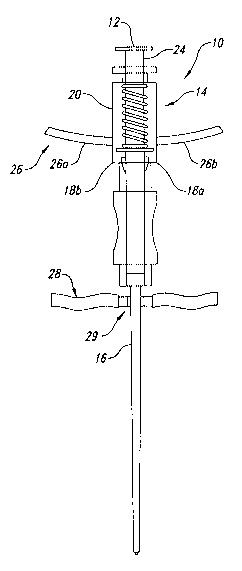
Figure 1 illustrates one embodiment of the invention implemented
as a spinal needle delivery system 10, that overcomes the complications
experienced with prior spinal needles. The system 10 both identifies contact
with and stabilizes the dura mater tissue. Tissue contact is identified by a
blunt-
tipped epidural space stylet (or simply stylet) 12 advanced through a cannula
under the influence of a biasing mechanism 14. The system 10 signals the
stylet's entrance into the epidural space and its contact with the dura mater
by
activating a combination tactile and visual signal portion of the stylet 12.
The
system 10 also stabilizes the dura mater by attachment of the distal tip of a
cannula 16 to the dura mater tissue. The identification of and attachment to
the
dura mater tissue provides directional control and depth control for a spinal
needle or catheter passed through the tubular cannula 16 and into the
subarachnoid space. This in turn facilitates the appropriate placement of a
catheter or blood patch into the epidural or subdural space.
As shown in Figures 2A-2B, the cannula 16 is a blunt-tipped
tubular body 17 having a longitudinal axis and terminating in a distal annular
port 42 surrounded by sharpened hooks or barbs 50. These barbs 50 may also
comprise sliver or scale-like serrations configured to at least partially
penetrate
the tissue. The blunt distal tip 52 of the cannula 16 prevents penetration of
the
membrane or tissue. The barbs 50 are configured for grasping and stabilizing
tissue encountered at the distal tip 52 of the cannula 16. The barbs 50 are
fashioned to engage a membrane or layer of tissue when the cannula 16 is
partially rotated about its longitudinal axis, preferably in a clockwise
direction
relative to the tissue, and to release or disengage from the tissue when the
cannula 16 is rotated in a reverse direction, preferably in a counterclockwise
direction.
Figures 2A and 2B together illustrate one embodiment of the
grasping barbs 50 of the invention that project from the blunt distal tip 52
of the
cannula 16. According to the embodiment illustrated, the barbs 50 are
configured as unidirectional sharpened sliver or scale-like serrations
distributed
around annular surface of the distal tip 52 surrounding the terminal port 42
and
4
CA 02472501 2004-07-02
WO 03/057282 PCT/US02/41574
are circumferentially aligned relative to the longitudinal axis of the bore 23
of
the cannula 16.
As is more clearly illustrated in Figure 2B, the barbs 50 project
from the blunt tip 52 of the cannula 16 at a shallow angle in order to more
effectively grasp tissue. The barbs 50 are alternatively fashioned in any
suitable form for grasping tissue as the cannula 16 is partially rotated about
its
longitudinal axis. For example, the barbs 50 are configured to insert into and
engage the outer portion of the dura mater when the cannula 16 is partially
rotated in the clockwise direction. According to one embodiment of the
invention, rotation of the cannula 16 by about 30 degrees fully engages the
barbs 50 in the dura mater tissue. While the barbs 50 are configured to grasp
the tissue, a further consideration is that the barbs 50 release the dura
mater
tissue when rotated in the opposite or counterclockwise direction.
Furthermore,
the barbs 50 are configured such that the dura mater tissue is not perforated
during either engagement or release. The blunt tip 52 of the cannula 16
further
facilitates the ability of the barbs 50 to grasp tissue without perforating or
puncturing.
The annular port 42 of the cannula 16 is sized to pass a spinal
needle or a catheter therethrough and into the subarachnoid space. Various
other lateral ports may be provided for the passage of an epidural catheter or
a
blood patch into the epidural space, as described in detail below.
As shown in Figure 3, an interior portion of the distal tip 52 of the
cannula 16 optionally includes a peripheral ring 44 useful as a depth-limiting
mechanism for a spinal needle of another tool. For example, the peripheral
ring
44 may also engage a stopper stylet or an epidural catheter guide of the
invention; both described in detail below.
In one embodiment, the cannula 16 may be about three and one-
half inches in length. A proximal end 19 of the cannula 16 is structured for
attachment of a distal portion 15 of the biasing mechanism 14. For example,
the proximal end 19 of the cannula 16 is fitted with one portion 18a of a
locking
mechanism or connector 18. The biasing mechanism 14 includes, for example,
a housing 20 containing a biasing member 22 implemented as a resilient
compression member. The housing 20 and biasing member 22 form a sleeve
that is fitted around a proximal portion 11 of the stylet 12. A distal end 21
of the
housing 20 is fitted with a mating portion 18b of the connector 18. The mating
5
CA 02472501 2004-07-02
WO 03/057282 PCT/US02/41574
portions 18a and 18b of the connector 18 are structured to be releaseably
coupled when the stylet 12 is slidably received within the cannula 16.
The blunt-tipped epidural space stylet 12 of the invention is sized
and shaped to be slidably received into a longitudinal axial bore 23 of the
cannula 16. The stylet 12 is structured with a blunt or rounded distal tip 36
that,
when inserted into the cannula 16, passes through the distal annular port 42
and projects beyond the distal tip 52 of the cannula 16. The biasing
mechanism 14 urges the distal tip 36 of the stylet 12 to normally extend or
project from the distal tip 52 of the cannula 16. The near or proximal end 11
of
the stylet 12 is coupled to the biasing mechanism 14 but is free to move
within
the bore 23 of the cannula 16, within predetermined limits. An indicator
portion
24 at the proximal end 11 of the stylet '12 is free to move in and out of an
aperture 34 at the proximal end 27 of the housing 20.
In this embodiment, the housing 20 includes a finger rest 26
implemented, for example, as a pair of lateral wing extensions 26a and 26b,
which are useful for supporting and operating the spinal needle delivery
system
10. The lateral wing extensions 26a and 26b are sized for grasping by the
fingers and to facilitate insertion of the cannula 16 into tissue.
An adhesive band 28 may be attached to the shaft on the exterior
of the cannula 16 by a cannula lock 29. The adhesive band 28 is to stabilize
the cannula 16 relative to the patient's body and prevent counter-rotation
thereof.
In operation, the distal tip 52 of the cannula 16 is inserted through
a previously incised perforation in the skin and muscle tissue until the
distal tip
52 of the cannula 16 contacts the dura mater surrounding the subarachnoid
space. As the cannula 16 and stylet 12 are advanced, the skin and underlying
muscle tissue present a relatively high resistance that causes the stylet 12
to
compress or "load" the resilient biasing mechanism 14. Loading the biasing
mechanism 14 causes the indicator portion 24 at the proximal end 11 of the
stylet 12 to project from the proximal end 27 of the housing 20. The indicator
portion 24 thus presents a tactile and visual indication that the distal tip
52 of
the cannula 16 and stylet 12 are advancing through relatively high resistance
muscle tissue.
When a lesser resistance is encountered, such as the epidural
space between muscle tissue and the dura mater, the biasing mechanism 14
automatically advances or "discharges" the distal tip 36 of the stylet 12 for
a
6
CA 02472501 2004-07-02
WO 03/057282 PCT/US02/41574
limited distance beyond the distal tip 52 of the cannula 16. Thus, upon
entering
the epidural space, the resilient biasing mechanism 14 is "unloaded," which
permits the indicator portion 24 at the proximal end 11 of the stylet 12 to
retract
into the proximal end 27 of the housing 20. Retraction of the indicator
portion
24 indicates entry of the distal tip 36 of the stylet 12 into the epidural
space.
The cannula 16 is then advanced over the stylet 12 until the distal
tip 52 of the cannula 16 encounters the dura mater, whereupon the cannula 16
is rotated about its longitudinal axis to engage the dura mater. This
stabilizing
the dura mater tissue so that a spinal needle, a catheter, or another tool can
be
delivered through the various membranes and tissues to the appropriate site.
As the cannula 16 is advanced over the stylet 12 to contact the dura mater,
the
stylet 12 can be withdrawn, sometimes simultaneously.
The optional adhesive band 28, if present, is adhered to the outer
membrane through which the distal tip 52 of the cannula 16 is inserted. For
example, in a spinal needle application, the adhesive band 28 is adhered to
the
patient's skin to help stabilize the installed cannula 16. After insertion and
engagement of the cannula 16, the adhesive band 28 is advanced to a position
along the cannula 16 near to the skin perforation at the entry point of the
cannula 16. The adhesive band 28 is then adhered to both the cannula 16 and
the patient's skin, thereby helping to maintain the depth and orientation of
the
cannula 16 relative to the perforation.
Loosening the adhesive band 28 and rotating the cannula 16 in
the reverse direction until the barbs 50 are released from the tissue
disengages
the cannula 16. The cannula 16 is retrieved by withdrawal from the incised
perforation.
Figure 3 illustrates the blunt epidural space stylet 12 installed in
the cannula 16. The biasing mechanism 14 is implemented using the resilient
compression member 22 captured within the housing 20. The resilient
compression member 22 is, for example, implemented as a spring or spring-like
mechanism, or other resilient material sized and shaped to provide a resistive
fo rce.
According to this embodiment of the invention, the spring 22 is
positioned between one or more engagement blocks 30 on the stylet 12 and an
inner surface 31 at the proximal end 27 of the housing 20. The engagement
blocks 30 are optionally implemented as one or more rigid lateral protrusions
30
that enlarge the outside diameter of the stylet 12. The engagement blocks 30
7
CA 02472501 2004-07-02
WO 03/057282 PCT/US02/41574
are sized to fit within the tubular bore of the cannula 16. The engagement
blocks 30 are located on the stylet 12 at a position that will interact with
the
spring 22, either directly or, in this case, through a reaction member 32. The
optional reaction member 32 is, for example, an annular disc having an inner
diameter sized to slidably engage the outer diameter of the stylet 12, but to
interfere with the engagement blocks 30.
In this embodiment of the invention, the housing 20 of the biasing
mechanism 14 is implemented as mating male and female portions of a
modified luerlock connector. A female portion of the luerlock connector is
provided as the connector portion 18a attached to the proximal end of the
cannula 16. The distal end of the housing 20 is formed of the male connector
portion 18b of the luerlock connector. The female 18a and male 18b connector
portions of the modified luerlock connector interconnect to form the locking
mechanism 18.
The spring 22 is initially compressed between the reaction
member 32 on the body of the stylet 12 and the inner proximal surface of the
housing 20 to provide a predetermined amount of pre-load force on the stylet
12. The normal expansion of the compressed spring 22 urges the distal tip 36
of the stylet 12 to project from the distal tip 52 of the cannula 16. The
spring 22
is selected to store an amount of pre-load force appropriate to the particular
application for which the invention is practiced. For example, when
implemented for a total spinal needle application, the spring 22 is selected
to
have a spring force that is less than~the force required to advance the distal
tip
52 of the cannula 16 through the perforation in the skin and the underlying
muscle tissue. Advancement through the skin and muscle tissue thus
compresses or "loads" the spring 22 with an increased pre-load and causes the
indicator portion 24 to project through the oversized aperture 34 in the
proximal
end 27 of the housing 20.
The spring 22 is further selected to have a spring force greater
than the lower resistance within the epidural space. Because the dura mater is
a pulsating tissue due to the pulsing of blood vessels in the spinal cord and
brain, the epidural space is periodically subjected to negative pressure. This
negative pressure will act to draw the stylet 12 into the epidural space. Upon
encountering such negative pressure or a lower resistance tissue, the spring
22
unloads to its normally expanded configuration and discharges the distal tip
36
of the stylet 12. For example, the distal tip 36 of the stylet 12 is
discharged
8
CA 02472501 2004-07-02
WO 03/057282 PCT/US02/41574
from the terminal port 42 in the distal tip 52 of the cannula 16 by
approximately
three to four millimeters. The extended indicator portion 24 of the stylet 12
is
retracted by a similar amount through the aperture 34 into the proximal end 27
of the housing 20.
The distance by which the distal tip 36 of the stylet 12 is moved by
the spring 22 is also selectable to satisfy various applications. According to
one
embodiment of the invention, the housing 20 cooperates with the a lateral
protrusion on the proximal end portion 11 of the stylet 12 to implement a
"depth-limiting" mechanism that controls the distance by which the distal tip
36
of the stylet 12 is projected from the distal tip 52 of the cannula 16. For
example, a proximal cap 38 on the proximal end portion 11 of the stylet 12 is
sized with an outer diameter larger than the aperture 34 in the proximal end
27
of the housing 20. The aperture 34 thus restricts the motion of the stylet 12
toward the distal tip 52 of the cannula 16 by interfering with the proximal
cap
38.
Alternatively, the engagement blocks 30 are sized larger than a
peripheral annular seat 40 portion of an inner distal surface of the housing
20.
The peripheral seat 40 interferes with the oversized engagement blocks 30,
thus providing a depth-limiting mechanism for the distal tip 36 of the stylet
12
relative to the distal tip 52 of the cannula 16.
According to another embodiment of the invention, the
engagement blocks 30 are sized larger than the inner diameter of the bore 23
of the cannula 16. The proximal opening into the cannula 16 interferes with
the
oversized engagement blocks 30. The proximal surface of the cannula 16 thus
provides a depth-limiting mechanism for the distal tip 36 of the stylet 12
relative
to the distal tip 52 of the cannula 16.
Figures 4A and 4B together illustrate another depth-limiting
mechanism of the invention. In Figure 4A, the epidural space stylet 12 of the
invention is shown in a discharged state, wherein the spring force of the
biasing
mechanism 14, as indicated by the directional arrow, urges the blunt distal
tip
36 of the stylet 12 to advance through the terminal port 42 in the cannula 16.
The peripheral ring 44 is sized with an inner diameter somewhat smaller than
the inner diameter of the tubular cannula 16. The peripheral ring 44 thus
provides a depth-limiting mechanism for the distal tip 36 of the stylet 12
relative
to the distal tip 52 of the cannula 16. For example, the stylet 12 is provided
with
a shoulder portion 46 at a predetermined setback distance from the extent of
9
CA 02472501 2004-07-02
WO 03/057282 PCT/US02/41574
the blunt distal tip 36. While the blunt distal tip 36 is sized to pass
through the
reduced diameter of the terminal port 42, the shoulder portion 46 is sized to
encounter the inner peripheral ring 44, which restricts projection of the
blunt
distal tip 36 to a predetermined distance beyond the distal tip 52 of the
cannula
16.
Figure 4B illustrates the epidural space stylet 12 in a loaded state,
wherein a resistance encountered at the distal tip 52 of the cannula 16 is
sufficient to overcome the spring force provided by the biasing mechanism 14.
In such circumstance, the blunt distal tip 36 of the stylet 12 is pushed back
inside of the cannula 16, lifting the shoulder 46 off of the inner peripheral
ring
44 and storing a predetermined pre-load in the biasing mechanism 14 as a
function of its spring rate.
As discussed above, the pre-load force is stored in the biasing
mechanism 14 until the distal tip 52 of the cannula 16 passes through the high
resistance tissue into a space, such as the epidural space, which presents a
resistance that is less than the spring force of the biasing mechanism 14.
The distal tip 36 of the epidural space stylet 12 is sufficiently blunt
to avoid inadvertently perforating tissue, such as the dura mater tissue, as
the
cannula 16 is advanced through the epidural space and into contact with the
dura mater.
The distal or terminal port 42 of the cannula 16 is sized to permit
the passage of a spinal needle or a catheter into the subarachnoid space.
Various other ports are provided in the lateral surfaces of the distal tip 52
of the
cannula 16. As shown in Figures 4A and 4B, a lateral epidural port 54 is
provided adjacent to the distal tip 52 and is sized to pass an epidural
catheter
or blood patch. Optionally, one or more smaller auxiliary lateral ports 56 are
provided near the distal tip 52 of the cannula 16. The smaller auxiliary ports
56
are useful, for example, for administering blood patches.
Figure 5 illustrates an embodiment of the blunt-tipped cannula 16
of the invention, including the peripheral ring 44 within the interior of the
terminal port 42, as described above. The peripheral ring 44 is sized with an
inner diameter somewhat smaller than the inner diameter of the tubular cannula
16. The peripheral ring 44 thus provides a depth limiting mechanism for a tool
acting at or through the distal tip 52 of the cannula 16. As shown in Figure
5,
the peripheral ring 44 is a depth limiting mechanism for a spinal needle 58.
The
spinal needle 58 or another tool intended to operate beyond the distal tip 52
of
CA 02472501 2004-07-02
WO 03/057282 PCT/US02/41574
the cannula 16 includes an active portion 60 that is sized to pass through the
reduced diameter terminal port 42. The maximum extension of the active
portion 60 is limited to about 6 mm by a shoulder 62 that is sized to
encounter
the inner peripheral ring 44. Interference between the shoulder 62 and the
inner peripheral ring 44 restricts further extension of the active portion 60.
Figures 6 and 7 together illustrate the use of an epidural catheter
guide 70 of the invention in combination with the blunt-tipped cannula 16 of
the
invention. The epidural catheter guide 70 is sized small enough to be
slidingly
received within the tubular bore 23 of the cannula 16, but sufficiently large
to
engage the inner peripheral ring 44 partially obstructing the terminal port
42,
which effectively restricts further advancement of the epidural catheter guide
70. The epidural catheter guide 70 is configured to direct an epidural
catheter
72 through the lateral epidural port 54. The epidural catheter guide 70 is
configured, for example, with a plug portion 74 at the distal end of a shaft
76.
The plug portion 74 is sized and shaped to interfere with the inner peripheral
ring 44 of the terminal port 42 and limit the further advancement of the shaft
76.
The shaft 76 intersects with the plug portion 74 in a curved
configuration that urges the catheter 72 into a directional change relative to
the
cannula 16. Furthermore, the plug portion 74 is sized to provide the
directional
change in proximity to the lateral epidural port 54 in the cannula 16.
As illustrated in Figure 7, the epidural catheter guide 70 is
configured to combine with the interior wall surface 78 of the cannula 16 to
form
a tube-like channel that slidably receives the tubular catheter 72 and directs
it
down to and through the lateral epidural port 54.
The shaft 76 of the epidural catheter guide 70 is, for example,
formed to have a partial tubular shape with an outer radial dimension Ro and
sized to be slidably received within the tubular bore 23 of the cannula 16.
The
shaft 76 has an inner radial dimension R, sized to permit easy advancement of
the epidural catheter 72 between the epidural catheter guide 70 and the inner
wall surface 78 of the cannula 16. In operation, the inner radial surface of
the
shaft 76 coordinates with the inner wall surface 78 of the cannula 16 to
direct
the catheter 72 down to and through the lateral epidural port 54 and into the
epidural space.
Figure 8 illustrates another aspect of the blunt-tipped cannula 16
of the invention. A stopper stylet 80 of the invention is inserted into the
previously stabilized cannula 16. According to one embodiment of the
11
CA 02472501 2004-07-02
WO 03/057282 PCT/US02/41574
invention, the stopper stylet 80 includes a stopper 82 positioned at a distal
tip of
a shaft 84. The stopper 82, which is formed of rubber or another resilient
material, is sized to be slidably received within the tubular bore of the
cannula
16, while its advancement beyond the distal tip 52 of the cannula 16 is
restricted by interference with the inner peripheral ring 44. Furthermore, the
stopper 82 is sized small enough to avoid obstructing the one or more
auxiliary
lateral ports 56.
The shaft 84 of the stopper stylet 80 is concentric with the stopper
82. The outer surface 88 of the shaft 84 thus cooperates with the inner wall
surface 78 of the cannula 16 to form an annular passage or channel 86
therebetween that communicates with the auxiliary lateral ports 56 through
which blood or another fluid may flow.
Operation
Figure 9 illustrates the use of the described embodiment of the
spinal needle delivery system 10 with a patient who is in any of the lateral
decubitus, sitting, and prone positions. An appropriate antiseptic preparation
is
completed on the patient's skin. A local anesthetic is administered to
anesthetize the tissues, inclusive of the lumbosacral fascia located just
cephalad to the spinous process, in the midline, of the selected interspinous
process space. The skin opening is enlarged to admit the distal tip 36 of the
blunt stylet 12. The blunt cannula 16 containing the blunt stylet 12 is
grasped
by the pair of lateral wing extensions 26a and 26b using the thumb and index
fingers of both hands. The middle, ring, and small fingers of both hands are
extended and applied to the paravertebral skin surfaces bilaterally to provide
a
stabilizing scaffold for the cannula 16 and stylet 12 as they are gradually
advanced through the enlarged skin opening.
Firm but steady pressure is applied to advance the needle
delivery system 10 into and through the enlarged skin opening. For example,
the needle delivery system 10 is advanced at the rate of approximately five
millimeters per second for about the first four centimeters and more slowly
thereafter, maintaining the needle delivery system 10 in the midline position
at
all times. As resistance to the advancement of the needle delivery system 10
is
encountered, the distal tip 36 of the blunt stylet 12 is forced into the
terminal
port 42 in the distal tip 52 of the cannula 16, thereby compressing the spring
22
of the biasing mechanism 14. Simultaneously, the indicator portion 24 of the
12
CA 02472501 2004-07-02
WO 03/057282 PCT/US02/41574
proximal end 11 of the stylet 12 is projected from the proximal end 27 of the
housing 20. The spinal needle delivery system 10 thus provides a tactile and
visual indication that the distal tip 52 of the cannuia 16 is engaged in
tissue that
resists the advancement of the needle delivery system 10 with a greater force
than the spring force of the biasing mechanism 14. In other words, projection
of
the indicator portion 24 from the housing 20 indicates that the distal tip 52
of the
cannula 16 is advancing through skin and muscle tissue.
As the distal tip 52 of the cannula 16 enters the epidural space
between the muscle tissue and the dura mater, the spring force of the biasing
mechanism 14 overcomes the lower resistance, and the blunt distal tip 36 of
the
stylet 12 is urged outwards through the terminal port 42 of the cannula 16.
Simultaneously, the indicator portion 24 at the proximal end 11 of the stylet
12
moves partially or completely into the aperture 34 in the proximal end 27 of
the
housing 20, thereby indicating that the epidural space as been penetrated. The
lateral wing extensions 26a and 26b are released by the user. The cannula 16
is grasped and advanced along the shaft of the stylet 12 about three to tour
millimeters, while the cannula 16 is rotated in a direction to engage the
barbs
50 with the dura mater tissue, for example, in a clockwise direction. The
advancing and rotating of the cannula 16 is curtailed when resistance to
continued rotation is encountered. The cannula 16 is supported in the engaged
position while the cannula lock 29 and the skin adhesive band 28 are advanced
along the shaft of the cannula 16 until the adhesive band 28 contacts but does
not depress the skin. The cannula lock 29 is locked to the shaft of the
cannula
16 to fix the adhesive band 28 relative to the cannula 16. The adhesive strips
of the adhesive band 28 are adhered to the skin. Further support of the
cannula 16 is unnecessary.
After the procedure is complete, the spinal needle delivery system
10 is removed in reverse order. The adhesive band 28 is separated from the
skin, the barbs 50 are disengaged from the dura mater by reverse rotation of
the cannula 16, and the cannula 16 is retrieved from the perforation.
Turning next to Figures 10A-10B, shown therein is another
embodiment of a spinal needle delivery device 90 that includes a cannula 92
having a blunt stylet 94 slidably mounted within a longitudinal axial bore 96.
The stylet 94 has a proximal end 98 mounted within a housing 100. The
housing 100 comprises a rotationally indexing male-type luer lock fitting 102
engaging a female-type luer lock coupling 104 in which a proximal end 106 of
13
CA 02472501 2004-07-02
WO 03/057282 PCT/US02/41574
the cannula 92 is mounted. A coil spring 108 inside the male-type fitting 102
acts upon a disc 110 attached to the stylet 94 to urge the distal end 112 of
the
stylet 94 to project out of the distal end 114 of the cannula 92. When the
stylet
94 encounters resistance that overcomes the force of the spring 108, the
proximal end 98 of the stylet 94 projects out of the top of the housing 100,
as
shown in Figure 10B.
Figures 11A-11 B show an alternative configuration for the distal
end 114 of the cannula 92. Here, the annular face 116 of the cannula 92 has
three barbs 118 formed thereon. It is to be understood that additional or
fewer
barbs may be used, and their configuration may vary in order to accommodate
certain tissues. The barbs 118 in this configuration each have first radially-
oriented side 120 and a second side 122 that converge to form a point 124.
The first side 120 is formed by the intersection of the top side 126 and the
bottom side 128 of the barb 118, as shown in Figure 11A and in the side view
of
the barbs 118 in Figure 11 B, which shows a side view of the annular face 116
in rolled out configuration.
In Figure 12, a spinal needle delivery device 130 is shown having
a depth limited spinal needle assembly 132 mounted to the housing 100 using
the male-type luer lock fitting 102 and corresponding female-type coupling 104
described above. The needle 134 projects out of the distal end 136 of the
cannula 138 in which are formed a catheter port 140 and a pair of blood ports
142.
The blood ports 142 are used with the device 144 shown in Figure
13, wherein a hollow stylet stopper 146 is slidably received within the
cannula
138. The stopper 146 has a tip 148 with a circumscribing channel 150 formed
therein. A transverse opening 152 formed through the channel intersects with a
longitudinal axial bore 154 of the stylet stopper 146. A rubber membrane 156
covers the proximal end 158 of the stylet stopper 146 that is mounted in the
male-type fitting 102.
The catheter port 140 is used with the device 160 shown in Figure
14. An epidural catheter guide 162 is used in conjunction with the male-type
fitting 102 and the cannula 138 to intersect with the catheter port 140 for
the
passage of fluids. A sidewail 164 of the catheter guide intersects the
catheter
port 140 at about a 45-degree angle to enhance the flow of fluids.
Figure 15 shows an alternative method of affixing the spinal
needle delivery device to the patient's skin. An attachment system 166
14
CA 02472501 2004-07-02
WO 03/057282 PCT/US02/41574
comprises first and second adhesive pads 168, 170, each formed in an L-shape
to have a first segment 172 sized for attachment to the patient's skin (not
shown) and a second segment 174 folded upward for attachment to the mating
second segment 174, such as by bonding stitches 1.76 or other conventional
fastening method. In this manner, an opening 178 is formed between the
second segments in which the cannula 180 is inserted. Pressure sensitive
adhesive on the second segments 174 affixes the cannula 180 to the two pads
168,170. An adhesive is used on the underside 182 of the pads 168,170 for
attachment to the patient's skin.
Alternatively, another attachment system 184 is shown in Figure
16 in which a locking block 186 is mounted to an adhesive skin patch 188.
More particularly, the locking block comprises a truncated cone base 190
having a bottom surface 192 afFixed to the top surface 193 of the skin patch,
such as by adhesive. A threaded fastener 194 is threadably received in the
base 190 to bear against and hold the cannula 196 in place. An adhesive on
the bottom surFace of the patch 188 holds the patch to the patient's skin (not
shown).
From the foregoing it will be appreciated that, although specific
embodiments of the invention have been described herein for purposes of
illustration, various modifications may be made without deviating from the
spirit
and scope of the invention. For example, the disclosed embodiments of the
invention will find application outside the embodiments described above, such
as a means of locating pain generators. Probes, such as electrodes, thermal
transducers, guided discography proves, and fiber optics, to name a few, can
be advanced through the cannula to view the epidural space and to localize and
differentiate pain generator sites. Accordingly, the invention is not to be
limited
except as by the appended claims and the equivalents thereof.