Note: Descriptions are shown in the official language in which they were submitted.
CA 02472692 2004-07-08
WO 03/061854 PCT/GB03/00166
APPARATUS FOR SEPARATING MATERIAL,
The present invention to an apparatus for separating
material, particularly, but not exclusively, solids from
used drilling mud. The present invention also relates to
a shale shaker, a screen assembly and a wear strip.
in the drilling of a borehole in the construction of
an oil or gas well, a drill bit is arranged on the end `of
a drill string and is rotated to bore the borehole. A
drilling fluid known as "drilling mud" is pumped through
the drill string to the drill bit to lubricate the drill
bit. The drilling mud is also used to carry the cuttings
produced by the drill bit and other solids to the surface
through an annulus formed between the drill string and
the borehole. The drilling mud contains expensive
synthetic oil-based lubricants and it is normal therefore
to recover and re-use the used drilling mud, but this
requires the solids to be removed from the drilling mud.
This is achieved by processing the drilling fluid. The
first part of the process is to separate the solids from
the solids laden drilling mud. This is at least partly
achieved with a vibratory separator, such as those shale
shakers disclosed in US 5,265,730, WO 96/33792 and WO
98/16328.
Shale shakers generally comprise an open bottomed
basket having one open discharge end and a solid walled
feed end. A number of rectangular screens are arranged in
the basket, which are held in C-channel rails located on
the basket walls, such as those disclosed in GB-A-
2,176,424. The basket is arranged on springs above a
receptor for receiving recovered drilling mud. A skip or
ditch is provided beneath the open discharge end of the
basket. A motor is fixed to the basket, which has a drive
rotor provided with an offset clump weight. In use, the
motor rotates the rotor and the offset clump weight,
CA 02472692 2007-01-26
2 -
vvhich causes the basket and the screens tixed thereto to
shake. Solids laden mud is introduced at the feed and of
the basket on to the screena. The shaking motion induces
the solids to move along the screens towards the open
diecharge end. The recovered drilling mud is received in
the receptor for further processing and the solids pass
over the discharge end of the basket into the ditch or
skip.
The prior art discloses a variety of mounting
systems and apparatuses for releasably mounting a screen
assembly to a shale shaker. These include drawbar and
hooketrip apparatuses; inflatable device systeme (as
described above); wedge systems; for example, the systems
described in US-A-6,179,128 issued Jan 30, 2001; US-A-
5,392,925 issued Feb. 28, 1995; IIS-A-4,882,054 issued
Nov. 21, 1989; US-A-4,582,597 issued Apr. 15, 1986; and
in the prior art referred to in each of these references.
A prior art shale shaker is shoMn in Figure S. The
shale- shaker 1 has a screen 2 (with screen or screening
cloth or mesh as desired) mounted on vibratable screen
mounting apparatus or Obasket^ 3. The screen Z=may be
any known screen or screens. The basket 3 is mounted on
springs 4 (only two shown; two as shown are on the
opposite side) which are supported from a frame 6. The
basket 3 is vibrated by a motor 5 and interconnected
vibrating apparatus 8 which is mounted on the basket 3
for vibrating the basket and the screens. Elevator
apparatus 7 provides for raising and lowering of the
basket end.
~ Figure 6 discloses an example of a prior art shaker
systen (for example as shown in US-A-5,190,645).
The system A has a shale shaker K having a screen or
screens S. The screen(s) S are mounted in a typical
shaker basket B and one or more vibrators V (any known
.35 suitable shaker
CA 02472692 2004-07-08
WO 03/061854 PCT/GB03/00166
- 3 -
vibrator) vibrate the basket B and hence the screen(s)
S. The other components of the system A are as
described in US-A-5,190,645.
The screens are generally of one of two types: hook-
strip; and pre-tensioned.
The hook-strip type of screen comprises several
rectangular layers of mesh in a sandwich, usually
comprising one or two layers of fine grade mesh and a
supporting mesh having larger mesh holes and heavier
gauge wire. The layers of mesh are joined at each side
edge by a strip which is in the form of an elongate hook.
In use, the elongate hook is hooked on to a tensioning
device arranged along each side of a shale shaker. The
shale shaker further comprises a crowned set of
supporting members, which run along the length of the
basket of the shaker, over which the layers of mesh are
tensioned. An example of this type of screen is disclosed
in GB-A-1,526,663. The supporting mesh may be provided
with or replaced by a panel having apertures therein.
The pre-tensioned type of screen comprises several
rectangular layers of mesh, usually comprising one or two
layers of fine grade mesh and a supporting mesh having
larger mesh holes and heavier gauge wire. The layers of
mesh are pre-tensioned on a rigid support comprising a
rectangular angle iron frame and adhered thereto. The
screen is then inserted into C-channel rails arranged in
a basket of a shale shaker. An example of this type of
screen is disclosed in GB-A-1,578,948.
A further example of a known rigid support is
disclosed in PCT Publication No. WO 01/76719, which
discloses, amongst other things, a flat panel like
portion having apertures therein and wing portions which
are folded to form a support structure, which may be made
from a single sheet of material. This rigid support has
been assigned the Trade Mark "UNIBODY " by the applicants.
CA 02472692 2004-07-08
~. ~ ~.
The layers of mash in the screens wears out
frequently and therefore needs t.o be easily zeplaceabZe.
Shale shakers are generally in the order af 5ft wide and
lOft long. A screen of dimensions 4ft wide by lOft long
is difficult to handle, replace and transport. ' It i,s
known to use two, three, four or more screens ia a single
shale ehaker. A atanda,rd size of acreen current].y used is
of the order of 4ft by 3ft.
- There is a need, recogniaod by the psesnnt
inventors, for an effiaient rsnd effective acreen mmounti.ag
st.ruoture and method for screen aasemblies for shal
shakers. There is a need xeoognised by the present
3.nv+antors, fo;e an afficiesst and stable mosnrrtx,ag of
screens to a shale shaker.
In accordance srlth the present invention, there is
provide9d a method for mouunti.ng a screen assembly a.n1 a
shale shaker, the shale shaker comprisiag a mounting
strncture ,for raceiv3.ng the screm assembly, the, rcreaa
assembly comprisiag at least one layer of screening
material tensioned ovar a screen support, claract8ri.sed
in that the method comprises the steps of aligning said
screen assembly with said awvmtiag structure using at
least one hole located in at least one of the screen
support and thoa mounting structure and :Lnsertiug a
corresponding pin into said at least one hole.
Preferably, the pia is f9.x+ad to, and projects from
one of said screen support and nomrsting structure aand the
at least one hole is located in the other of said screen
support and mounting structure, the method comprising the
step of locating tha pin ovzth the hole of the other of
said screen support and mounting structure.
Advantageously, both of the screen support aad the
mounting structure co prSi-sQ at least one hole; the inethod
comprising the steps of aligni,ng said hol s and plaaing
the pin through the at least one hole on the screen
CA 02472692 2004-07-08
support and into at least one hole in the moQnting
structure.
Preferably, a further hole is located i.n at least
one of the scseen support and the mounting structure the
method furthor comprising the step of locating a fttrther
pin in the further holes.
The present 3.nveatian also providea a soree=-ixtg
appazatur+ for sepaxating solids from a solids laden
drilling mud, said screaairig apparatus comprising a shale
shaker and a screen asswably mouated therein, sa3.d shale
shaker having a mounting structure., the screen assembly
eompri.sing at least one layer of screening material
taneione+d to a scremn suppost, aharacterised 3.n that at
least one hole is located in at least oane of said screen
support and said mounting structure, the screening
apparatus further coaaprisiag a pin receivable in said at
least one hole.
Prefeyrably, the pin is fixed and projects froa ona
of said screen support and said mountiag xtructssre and
said at least oila hole a.e loCatad in the other of said
acreen support and mounting structure. Advantagqeously,
said p3.n projects subst.antia].ly perpendi.calar from said
screen support or said mounting structure. Preferably,
said pin projects at ati auQle other than a right angle to
said screen support or said mounting structure.
Advaatageoarasly, the mounting strncture has an outer
psriphvey and said pia up.ratdly projects fram said outer
pari.phery. Preferably, said pin tapers from a base with a
base l.axgest dimension to a top ora.th a top largest
diamnsion, the bas largest dimensi.on, larger than the
top largest dimension. Advantaageously, the pin has a
ahape vieoaed from above from the group consistiag of
aircle, squara, rectangle, triangle, oval,' ellipse,
pentagon and hexagon. Preferably, the-mounting structure
cmaprises a xeax strip, said pin upwardly projecting frcia
CA 02472692 2004-07-08
said xear strip.
Prefasably, the screen support and mounta.ng
sts-acture compriae at least one hole, wherein said pin is
placed through said at least one hole on the screen
support and into at ].east oae hole in the support
structuz-e .
Advantageously, a further hola located in at least
one of the screea support and the mounting atructure and
a corresponding further pin.
Preferably, a plural3.ty of holes is located in at
leaat one of the screen support and the mounting
structure and the screening=apparatua further co prises a
corr sponding f'u:rther plurality of pine.
Advaatageously, the mounting structure comcprises a
deok of aaid shale ahaker. Preferably, the mounting
atraatuxe +xompsimes a tray.
Preferably, the aeroera supZaort is from the - group
consisting of grame, strip support and perforated plate.
Advantageausly, the sareen eupport camprises a flat panel
like portion havs.ag apertures therein and wing portions
xhich are folded to fosm a support structure, .rhicb may
be made froia a singrle =she4t of material. The applicants'
have assigned the Trade Mark MTISOD2 to this type of
suppart sttvvtnre.
Advanta-geously, the soteen assembly further
cvao~srises hook-etrips.
Preferably, the at least one layer of mesh is fixed to
said screen support. Advantageously, the at least. one
layer of screeaing material is fixed to said screen
support with hot melt glue. Prefarably, the screen
assembly further coaapris s at least a further layer of
screening saatterial.
CA 02472692 2004-07-08
WO 03/061854 PCT/GB03/00166
- 7 -
structure. Preferably, the screen assembly further
comprises at least two fine layers of screening mesh. One
or three layers of fine screening material may be used.
Advantageously, the screen assembly further comprises a
supporting mesh underlying the at least two fine layers
of screening mesh. Preferably, the fine layers of
screening mesh are glued together using lines of glue.
The screen assembly may be of the hookstrip type and
comprise at least one layer of fine mesh arranged on a
lower supporting mesh and/or a perforate plate and a
hookstrip arranged on two opposing sides of the mesh. The
upstanding members or holes arranged in said perforate
plate/supporting mesh between said hookstrips. The layers
of mesh may be glued together.
A screen assembly in accordance with the present
invention may be any known shale shaker screen or screen
assembly to which the pin(s), stud(s), and/or finger(s)
are added.
The present invention also provides a wear strip of
the apparatus of the invention.
Wear strips that are made in an originally upwardly
bowed configuration can provide such an upward force or
an initially flat wear strip that is installed so that
it bows slightly upwardly can provide such a force.
30
CA 02472692 2004-07-08
WO 03/061854 PCT/GB03/00166
- 8 -
For a better understanding of the present invention,
reference will now be made, by way of example, to the
accompanying drawings, in which:
Figure 1A is a top plan view of a screen assembly in
accordance with the present invention with a screen
support in accordance with the present invention;
Figure 1B is a side view of the screen assembly of
Figure 1A.
Figures 2A is a side view in cross-section of
fastener system for use in releasably connecting a screen
assembly in accordance with the present invention to a
shale shaker;
Fig 2B shows the fastener of Figure 2A in position
connecting a screen assembly to a shale shaker;
Figure 3A is a side view in cross-section of
fastener system for use in releasably connecting a screen
assembly in accordance with the present invention to a
shale shaker;
Fig 3B shows the fastener of Figure 3A in position
following activation connecting a screen assembly to a
shale shaker;
Figure 4 is a side view in cross-section of a
fastener system releasably connecting a screen assembly
according to the present invention to a shale shaker;
Figure 5 is a perspective view of a shale shaker;
Figure 6 is a schematic view of a prior art system
for processing drilling mud including a shale shaker;
Figures 7 to 9 are perspective views of shale
shakers in accordance with the present invention;
Figure l0A is a schematic view of a system in
accordance with the present invention;
Figure 10B shows a shale shaker of the system of
Figure 10A;
Figures 11, 12 and 15 are top plan views of screen
assemblies in accordance with the present invention, with
CA 02472692 2004-07-08
WO 03/061854 PCT/GB03/00166
- 9 -
parts of layers of screening material cut-away.
Figure 13 is a top plan view of a frame in
accordance with the present invention;
Figure 14A is a top view of a plastic grid in
accordance with the present invention;
Figure 14B is a perspective view of a plastic grid
in accordance with the present invention;
Figure 16 is a cross-sectional view of a screen
assembly in accordance with the present invention;
Figure 17 is a perspective view of a frame support
for a screen assembly in accordance with the present~
'invention;
Figure 18A is a top plan view of a screen assembly
in accordance with the present invention;
Figure 18B is an underneath view of the screen
assembly of Figure 18A;
Figure 18C is a view of one end of the screen
assembly of Figure 18A, the opposing end identical to the
end shown;
Figure 18D is a side view of one side of the screen
assembly of Figure 18A, the opposing side identical to
the side shown;
Figure 18E is a perspective view of part of the
screen assembly shown in Figure 18A showing part of the
underneath, one side and one end of the screen assembly;
Figure 18F is a perspective view of part of the
screen assembly of Figure 18A, showing a central part of
the underneath of the screen assembly.
Figure 19 is a perspective view of a screen assembly
mounting structure for a shale shaker in accordance with
the present invention;
Figure 20A is a top plan view of a screen assembly
in accordance with the present invention; Figure 20B is
an end view, Figure 20C is a side view and Figure 20D is
an underneath view of the screen assembly of Figure 20A;
CA 02472692 2004-07-08
WO 03/061854 PCT/GB03/00166
- 10 -
Figure 20E is a top view of possible hole shapes in
accordance with the present invention for the screen
assembly of Figure 20A.
Figure 21 is a perspective view of a screen assembly
mounting structure for a shale shaker in accordance with
the present invention;
Figure 22 is a perspective view of a screen assembly
mounting structure for a shale shaker in accordance with
the present invention;
Figure 23A is a top view of a screen assembly in
accordance with the present invention; Figure 23B is an
end view, Figure 23C is a side view and Figure 23D is a
bottom view of the screen assembly of Figure 23A;
Figure 24 is a perspective view of a screen assembly
mounting structure for a shale shaker in accordance with
the present invention;
Figures 25A to 25F and 25H are side schematic views
of shale shakers in accordance with the present
invention;
Figure 25G is a side view of a screen assembly for
the shale shaker of Figure 25H;
Figure 26.is a perspective view of a shale shaker in
accordance with the present invention;
Figure 27 is a perspective view of a shale shaker in
accordance with the present invention;
Figure 28 is a top plan view of a wear strip in
accordance with the present invention;
Figure 29A is a top plan view of a wear strip in
accordance with the present invention; Figure 29B is a
side view of the wear strip of Figure 29A;
Figure 30A is a top plan view of a wear strip in
accordance with the present invention; Figure 30B is a
side view of the wear strip of Figure 30A;
Figure 31A is a top plan view of a wear strip in
accordance with the present invention; Figure 31B is a
CA 02472692 2004-07-08
WO 03/061854 PCT/GB03/00166
- 11 -
side view of the wear strip of Figure 31A;
Figure 32A is a top plan view of a wear strip in
accordance with the present invention; Figure 32B is a
side view of the wear strip of Figure 32A; Figure 32C
is a side view of an alternative embodiment of the wear
strip of Figure 32A; Figures 32D and 32E are top plan
views of wear strips in accordance with the present
invention;
Figure 33 is a perspective view of a screen assembly
mounting structure for a shale shaker in accordance with
the present invention;
Figure 34A is a top plan view of a wear strip in
accordance with the present invention; Figure 34B is a
side view of the wear strip of Figure 34A;
Figure 35A is a top plan view of a wear strip in
accordance with the present invention; Figure 35B is a
side view of the wear strip of Figure 35A;
Figure 36A is a top plan view of a wear strip in
accordance with the present invention; Figure 36B is a
side view of the wear strip of Figure 36A;
Figure 37A is a top plan view of a wear strip in
accordance with the present invention; Figure 37B is a
side view of the wear strip of Figure 37A;
Figure 38A is a top plan view of a wear strip in
accordance with the present invention; Figure 38B is a
side view of the wear strip of Figure 38A;
Figure 39A is a top plan view of a wear strip in
accordance with the present invention; Figure 39B is a
side view of the wear strip of Figure 39A;
Figure 40A is a top plan view of a wear strip in
accordance with the present invention. Figure 40B is a
side view of the wear strip of Figure 40A.
Figure 41A is a top plan view of a wear strip in
accordance with the present invention; Figure 41B is a
side view of the wear strip of Figure 41A;
CA 02472692 2004-07-08
WO 03/061854 PCT/GB03/00166
- 12 -
Figure 42 is a perspective view of a screen assembly
mounting structure for a shale shaker in accordance with
the present invention;
Figure 43 is a perspective view of a screen assembly
mounting structure for a shale shaker in accordance with
the present invention;
Figure 44 is an underneath view of a wear strip of
Figure 43;
Figure 45 is a perspective view of a screen assembly
mounting structure for a shale shaker in accordance with
the present invention, shown with exploded parts;
Figure 46 is a perspective view of a screen assembly
mounting structure for a shale shaker in accordance with
the present invention;
Figure 47 is a perspective view of a screen assembly
mounting structure for a shale shaker in accordance with
the present invention;
Figure 48 is an underneath view of a screen assembly,
in accordance with the present invention;
Figure 49A is a perspective view of an upstanding
member suitable for any of the embodiment of the present
invention disclosed herein;
Figure 49B is a perspective view of a hole for
receiving the upstanding member shown in Figure 49A;
Figure 50A is a top view of a screen assembly in
accordance with the present invention; Figure 50B is a
side cross-section view of the screen assembly of Figure
50A;
Figure 50C is a top view of a screen assembly in
accordance with the present invention; Figure 50D is a
side cross-section view of the screen assembly of Figure
50C;
Figure 50E is a top view of a screen assembly in
accordance with the present invention; and Figure 50F is
a side cross-section view of the screen assembly of
CA 02472692 2004-07-08
WO 03/061854 PCT/GB03/00166
- 13 -
Figure 50E.
Figure 50G is a top view of a screen assembly in
accordance with the present invention.
Figure 51 is a side view of a wear strip in
accordance with the present invention.
Figures 1A and 1B show a screen assembly 10 in
accordance with the present invention which has a
perforated plate 11 on which is mounted three layers 12
of mesh or screening material. One, two, four, or more
layers of screening material may be used. The plate 11
has a plurality of side holes 18 on each of two of its
sides for receiving releasable fasteners for mounting
the screen 10 in a suitable shale shaker. Optionally,
the screen assembly's plate 11 may also have inner
portions 15 with holes 16 therethrough and/or inner
portions 15a with interior holes 16a therethrough which
holes are also for receiving releasable fasteners for
releasably connecting the screen assembly to the shale
shaker. To insert the fasteners through the holes 16,
16a and 18 into holes in a deck or bed below a screen
assembly, corresponding and appropriate holes or
openings are made in the screening material. Although
the entire inner portions 15a are revealed in Figure 1A,
in an actual screen assembly, prior to making holes in
screening material, the holes 16a and inner portions 15a
are covered by screening material.
Figure 2A shows a fastener system 20 in accordance
with the present invention which has a top member 21 with
a lower portion 22 that is received within a bottom
member 23 which has a plurality of spaced-apart fingers
24. The lower portion 22 upon insertion into the bottom
member 23 forces the fingers 24 apart for a tight
friction fit of the lower portion 22 within the bottom
member 23. An upper shoulder 25 of the bottom member 23
abuts the top surface of a screen assembly SC which may
CA 02472692 2004-07-08
WO 03/061854 PCT/GB03/00166
- 14 -
be any screen assembly according to the present
invention. A shale shaker deck 26 has a hole 27
corresponding to a hole 27a through the screen assembly
SC through which is mounted the bottom member 23. Any
fastener hole in any screen assembly or part thereof in
accordance with the present invention and/or any
corresponding hole through a shaker deck according to
the present invention may have any desired opening shape
as viewed from above, including, but not limited to,
rectangular, triangular, elliptical, oval, pentagonal,
circular, and hexagonal.
Figure 2B shows the fastener system 20 releasbly
holding the screen assembly SC to the shaker deck 26.
Spaced apart shoulders 28 and 29 of the top member 21
provide an abutment against the screen assembly SC (the
bottom shoulder 28) and a structure (the top shoulder
29) to grasp or contact to facilitate removal of the
fastener.
Figures 3A and 3B show another embodiment of a
fastener system in accordance with the present invention
for releasably connecting a screen assembly to a shale
shaker. A system 30 has a fastener 31 with a body 32
and a lower inflatable member 33. A stop shoulder 39 on
the body 32 abuts the top of a screen assembly SC (like
that of Figure 2A). Following insertion of the body 32
through a hole 34 in the screen assembly SC (see Figure
3A), the inflatable member 33 is inflated through valve
apparatus 35 to hold the fastener (and thus the screen
assembly) in place. To release the fastener, the valve
apparatus is activated to allow air to escape from the
inflated inflatable member 33. The inflatable member 33
is sized and positioned so that, upon inflation, it
abuts an underside of the deck 36 (like the deck 26,
Figure 2A) of a shale shaker.
Figure 4 shows a fastener 40 for releasably
CA 02472692 2004-07-08
WO 03/061854 PCT/GB03/00166
- 15 -
connecting a screen assembly SC (like that of Figure 2A)
to a shale shaker with a deck 46 (like the deck 26,
Figure 2A). The fastener 40 has a body 41 that is
inserted through a hole 42 in the screen assembly SC.
Optional threads 43 on the fastener body 41 mate with
corresponding threads 44 on the deck 46 to releasbly
hold the fastener, and thus the screen assembly, in
place. Any fastener in accordance with the present
invention and any deck in accordance with the present
invention may have such threads. Optionally, the,
threads are deleted and the fastener is held in place
with a friction fit; and/or, glue, epoxy, or an adhesive
is used to hold the fastener in position (as may be done,
optionally, with any other fastener disclosed herein); or
a non-threaded locking fastener is used with required
holes and/or surfaces on the shaker deck or bed. Any
suitable screw or bolt may be used for the body 41.
Optionally, the fastener 40 has a top head 45 that
facilitates turning of and removal of the fastener 40.
Any fastener in Figures 2A - 4 may be used with any
screen assembly disclosed herein.
It is within the scope of this invention for the
screen assembly SC to have one, two, three or more
layers of screening material, i.e., screen, mesh, and/or
cloth made, for example, of stainless steel wire and/or
plastic. Any such layer or combination of layers may be
bonded together (glued, welded, and/or sintered) in any
known manner and/or bonded to the plate 11 in any known
manner. Any such layer or layers of screening material
may be substantially flat or may be undulating (with a
series of alternating ridges and valleys) as is well
known in the art. in accordance with the present
invention any known support, plate, strip support, or
frame for supporting a shale shaker screen and/or for
mounting thereto of one or more layers of screening
CA 02472692 2007-01-26
- 16 -
material, azesh, and/or cloth may have one or more holes
for receiving one or more fasteners according to the
present invention for releasably connecting a screen
assembly to a shale shaker.
Figure 7 shows a ahale shaker 70 in accordance with
the present invention which is like a shaker disclosed in
US-A-5,641,070 co-owned with the present invention;
but the shaker 70 has a basket 71 with screen
mounting decks 72
and 73. Supports 72a of the deck-72 and supports 73a and
73b of deck 73, have holes 72b, 72c, 72d and 72e
therethrough (in deck 72) and 73c, 73d, 73e (in deck
73). As desired such holes may be provided on all sides
and/or on all cross-members of either or both decks.
These holes are sized and positioned to correspond to
holes in a screen support land, optionally, holes through
screening mash and/or cloth) of screen assemblies (not
shown) to be mounted in the basket 71. Springs 75 (two
shown; four, six or more may be used) support the basket
in a shaker body 76 and one or more vibrators 77
connected to the basket 71 vibrate the basket 71. Holes
as in either.or both decks 72, 73 may be provided for the
deck(s) of any known multi-deck shale shaker so that
screen assemblies in accordance with the present
invention with holes according to the present invention
may be releasably fastened thereto.
Figure 8'shows a shale shaker 80 in accordance with
the present invention with screen assemblies 81, 82 in
accordance with the present inveatioan mounted in a basket
83 to decks 86, 87 with fasteners 84, 85 which may be
any screen assembly disclosed herein according to the
present invention. The fasteners 84, 85 extend through
holes (not shown) in the screen assemblies into holes
(not shown) in the decks 86, 87. The basket 83 is
mounted on spring mounts 88 (three shown; four used in
CA 02472692 2004-07-08
WO 03/061854 PCT/GB03/00166
- 17 -
this embodiment) and is vibrated by a vibrator 89.
Referring now to Figure 9, a shale shaker 90 in
accordance with the present invention has a screen deck
92 in accordance with the present invention in a basket
91. The deck 92 has holes 93 therearound into which are
releasably inserted fasteners (not shown; including, but
not limited to, fasteners as disclosed herein and/or
fasteners in accordance with the present invention) to
releasably secure one or more screen assemblies (not
shown) to the deck 92. Any screen in accordance with
the present invention may be used on the deck 92. The
basket 91 is mounted on springs 94 (only two shown; two
as shown are on the opposite side) which are supported
from a frame 96. The basket 91 is vibrated by a motor
99 and interconnected vibrating apparatus 98 which is
mounted on the basket 91 for vibrating the basket and
the screens. Optional elevator apparatus 97 provides
for raising and lowering of the basket end.
Referring now to Figures 10A and 10B a well 111 is
being drilled by a bit 112 carried on a string of drill
pip 114. Drilling mud is pumped by a pump 118 into the
drill pipe 114 and out through nozzles in the bit 112.
The mud cools and cleans the cutters of the bit and then
passes up through a well annulus 116 flushing cuttings
out with it.
After the mud is removed from the well annulus 116,
it is treated before being pumped back into the pipe
114. First, the mud enters the shale shaker 110 where
relatively large cuttings are re moved. The mud then
enters a degasser 124 where gas can be removed if
necessary. Degasser 124 may be automatically turned on
and off, as needed, in response to an electric or other
suitable signal produced by a computer 124 and
communicated to degasser 124 as indicated by line 125.
The computer 1344 produces the signal as a function of
CA 02472692 2007-01-26
- 18 -
data from a seneor assembly 136 associated with shale
shaker 110 and deacribed more fully below. The data from
sensor assembly 136 is communicated to computer 134 by
line 182. The mud then passes to a desander and (or a
desilter), jointly represented by station 126, for
removal of smaller solids picked up in the well.
The mud next passes to a treating station 128 where,
if necessary, conditioning media, such as barite, may be
added frca source 130. Aa shown, suitable flow control
means, .3.ndicated in a simp].ified form by valve 132,
controls flow of media frosn isource 130 to station 128.
Valve 132, in turn, may be automatically operated by an
electric or other suitabl= signal produced by eamtputer
134 as a function of the data from sensor assembly 136;
such signal being cemamznicated to valve-132 as indicated
by line 131. 1
From the station 128, the mud is directed to tank
140, from which pump 118 takes suction, to be re-cycled
through the well. Any shale shaker disclosed herein may
be substituted for the shale shaker 110. The system 100
is like the systems disclosed in U.S. Patent
5,190,645, but the system 100 has a shake
shaker in accordance with the present invention.
The shale shaker 110 as shown in detail in Figure
108 has a basket 121 in which a screen mounting deck 122
(ehown achematically in Figure 108). A screen assembly
123 in accordance with the present invention (shown
schematically) ia releasably secured to the deck 122 by
a plurality of spaced-apart fasteners 133 which extend
through holes 135 in the screen assembly 123 and through
corresponding holes 137 in the deck 122. Vibrator
apparatus 139 vibrates the baoket 121 which is aeounted
on mounts 127. Material flovrs through exit structure
141 into a collection receptacle 143.
CA 02472692 2007-01-26
- 19 -
The screen aeeembly 123 may be aay (one, two, three
or more) screen assembly in accordance with the present
invention and the fasteners 133 may be any fastener 3.n
accordance with the present invention.
Figure 11 shows a screen assembly 190 in accordance
with the present invention which has a lower tubular
frame support 191 to which is connected and/or welded=a
perforated plate 192 (including, but not limited to =a
perforated plate like that disclosed in US-A-4,575,421;
but with holes in accordance with the present invention
for receiving fasteners in accordance with the present
invention to releasably connect the screen assembly 190
to a shale shaker).
The perforated plate 191 of the screen assembly 190
has a plurality of peripheral holes 193 and a plurality
of interior holes 194 (either holes 193 or holes 194 may
be deleted - as is the case for any support, plate, or
frame in accordance with the present invention).. A
plurality of fasteners 195 (two shown; one through = each
hole 193, 194) connect the plate 192 to the tubular frame
support 191. The fasteners, lower ends are received in
holes 196 of the tubular frame support 191 whose
position corresponds to that of the holes 193, 194.
As shown in Figure 11 there are three laye.ra 197a,
197b, 197c of screening material on the plate 192. Any
one or two of theee layers may be deleted; any knoarn
combination of layers may be uaedj and the layers may or
may not be eonnected and/or bonded together at their
edges and/or across their surfaces in any known manner
with any kiown material and/or process. Any known
suitable tubular members may be used to make the tubular
=
graxae support 191 with its outer members 191a and its
cross-members 191b.
Figure 12 shovrs a screen assembly 210 a.n accordance
CA 02472692 2007-01-26
- 20 -
with the present invention with a unibody structure 220
in accordance with the present invention. The screen
aasembly 210 has, optionally, three 211, 212, 213 of
screening material (shown partially; extending over the
entire open area of the unibody structure 220) bonded to
a top surface 222 of the unibody structure 22Ø
Preferably, the layers 211, 212, 213 are also bonded
together over substantially their entire surface area.
A plurality of fasteners 240 extend through holes 241 in
the unibody structure 220 to releasably connect the
screen aasembly 210 to a screen mounting deck 242 of a
ahale shaker (not shown in its entirety). Optionally,
one= or more fasteners 243 (one shown) may extend through
the layers of sereening material on the screen assembly
210 and into the deck 242.
A plurality of openings 224 through the unibody
structure 220 define a plurality of support members 226.
To the underside of the unibody structure 220.are,
optionally, connected a plurality of spaced-apart ribs
228 which, in one aspect are welded to a metal unibody
structure 220. In this particular embodiment the ribs
228 are positioned along a substantial majority of their
length directly beneath one of the support members 226
that extend across a major portion of the unibody
structure 220= but it is 'vithin the scope of this
invention to use no such ribs or to position them
anywhere on the underside of the unibody structure 220.
The unibody structure 220 has spaced-apart sides 236,
238. The acreen assembly 210 has an end 214 and a ledge
end 216. The ledge end has an upper ledge portion that
rests on a shoulder of an end of an adjacent screen. Thus one screen end seals
against another screen end
when such screens are used end-to-end (as described in
U.S. Patent 6,283, 302 co-owaed with the present
invention.
CA 02472692 2007-01-26
- 21 -
Figure 13 shows a screen strip support 250, in
accordance with the present invention with a plurality of
spaced-apart strips 252 (made of any suitable metal or
metal-like material) secured to and between spaced-apart
sides 254. The screen strip support 250 is like the
etrip support of Figure 51A, US-A- 6,290,068 (co-owned
with the present invention); but the screen
strip support 250 has
auter holes 267 and inner holes 268 through which may be
inserted any fastener disclosed herein for releasably
connecting the support 250 (and any screen assembly of
.uhich it is a part) to a shale shaker deck. Either
holes 267 or_holas 268 may be deleted. Any known strip
support may be provided, in accordance with the present
invention, with holes 267 and/or holes 268. Sach end
256 -of each strip 252 is received and held in a recess
264 in a side 254. The recess 264 corresponds in shape
to the shape of the end - 2 56 and a shoulder 2 6 6 of each
strip 252 abuts a side 254. The end 256 may.be inserted
into the recess 254 from the side or from above or below.
The top and bottom stripa 252 each has two humps or
ridges 253 which are located, sized, and configured to
be received in corresponding corrugations of a
corrugated plate and/or corrugated screen assembly. it
is within the scope of this invention for each strip to
have one, two, or a plurality of multiple humps or
ridges. In one aspect there is one hump or ridge for
each corrugation on a superimposed plate and/or screen
assemb].y. It is within the scope of this invention to
delete the humps and/or ridges so that the strips 252
are flat for" use with flat mesh and/or screen (s) .
Figures 14A and 148 show plastic grids 270, 271,
respectively, each with a body 270d, 271d respectively
with a plurality of openings 270a, 270b, 271b
respectively, therethrough. Although only certain of
CA 02472692 2007-01-26
- 22 -
the openings 271b are shown, it is to be uaderstood they
extend across the entire surface of the body 271d. The
plastic grids 270, 271 are like plastic grids disclosed
'
in V.S. Patents 5,417,8591 5,958,236; 5,783,077; and
6,053,332; but the grids 270, 271 each have +
a plurality of spaced-apart holes 270c,
271 c, respectively -
therethrough for accomoaa4odating fasteners according to
the present invention vrhich extend through a screen
assembly in accordance with the present invention to
releasably connect a screen assembly to a shale shaker.
Any grid disclosed in the patents cited above and any
known plastic grid or piece used in a screen assembly
for a ahale shaker may have holes as shown in Figures 14A
and 14B (and/or any holes disclosed herein for any
perforated plate or support disclosed herein);and any
screen or screen assembly disclosed in the patents cited'
above may have any such grid or piece. Any such grid or
piece in.aecordance with the present invention may have
holes corresponding to any fastener holes as described
herein. In one aspect the holes in the grid or piece are
made, in accordance with the present invention, prior to
the final formation or assembly of a screen or screen
assembly (as may also be the case with any parforated
plate or strip support in accordance with the present
invention); while in another aspect the holes are made
through the plastic grid (and/or through other parts,
piecee and/or layers of the screen or screen assembly)
followiag final formation or assembly thereof (as may
also be the case with any perforated plate, frame or
strip support in accordance with the preaent invention).
It is to be understood that it is within the scope of the
present invention to have a plastic layer or a mass of
fusiag plastic fusing together layers of screening
material, the layer or mass optionally provided
CA 02472692 2007-01-26
- 23 =
initially by a plastic grid, the plastic layer or mass
having holes for fasteners corresponding to holes in a
screening material support.
Figure 15 shows a screen assembly 280 in accordance
with the present invention with a lower supporting-
perforated plate 281 according to the present invention.
The screen assembly 280 is like those. disclosed, for
example, in US-A-4,575,421; but without hookstrip mounting
apparatus and with a plurality of peripheral
holes 282
and one or more interior holes 284 for receiving
fasteners 283 to releasably connect the screen assembly
280 to a shale shaker (not shown) whose deck or mounting
strueture..: has eorrespondf.ng holes for releasably.
receiving a portion of the fasteners 283= (as is the case=
for a shale shaker and* fasteaers through any screen or
screen assembly in accordance with the present
invention). 2n certain= preferred aspects holes 282
and/or 284 are eimply added to a perforated plate as
shown in US-A- 4,575,421; while in other aspects the
plate is initially made so that plate portione 288 have
only a hole 282 or a hole 284. In one particular aspect
(as is true for any perforated plate in accordance with
the present invention) an area like the areas 288
(and/or like the areas 15, Figure 1A and/or like the
areas around the holes 193, 194, Figure 11 and for any
plastic grid or piece in accordance with the present
invention) are at least as large (viewed from above) as
one of the openings or perforations through the plate
and in another preferred aspect are at least twice as
large (vieived from above) as such an opening or
perforation.
One, two, or three (or more) layers of mesh and/or
screening material may, in accordance with the present
invention, be used on a perforated plate 280 (or on any
CA 02472692 2007-01-26
- 24 -
perforated plate in accordance with the present
invention); for example, as shown in Figure 15, three
layers 285, 286, and 287 are used on the plate 281. Although these layera are
shown partially, it is to be
understood they substantially cover the plate 281.
The prior art discloses a variety of non-flat
screens and screen assemblies sometimes referred to as
03D or 'Three Dimensional" screens (for example, but
not limited to, as disclosed in VS-A-s 5,417,793f
5,417,858; 5,417,8591 6,053,332; 5,598,2361 5,783,0771'
6,283,302; 6,290,068. Figure 16 illustrates
that, in accordance
with the present invention, non-flat screen assemblieis,
may be fastened: with releasable fasteners passing
through holes therethrough to a shale shaker. A sereen'
assembly 290 (shown partially) has a'lorver perforated
plate 291 (which, optionally, may be any support plate,'
frame, or strip support) with a plurality of spaced-apart=
openings 292 therethrough (see, for example, but not
limited to, Figure 13, U.S. Patent 5,417,858; and Figure-
3, US-A- 5,417,859 regarding possible plates and
screening material). A plurality of fasteners 295
paseing through holes 296 (in screening material 294),
holes 297 (in the plate 291) and into (and, optionally,
through) holes 298 (in a shaker deck 293).
As shown ia. Figure 16, it is also within the scope
of this invention to employ one or more fasteners 299
which extend through a portion of the screening material'
294 that is not directly adjacent the plate 291 but
which is spaced-apart therefrou. As shown a fastener
299 passes through a highest (with respect to the plate
291 as viewed in Figure 16) portion of the screening
material 294 and through holes 299a, and 299b, in the
plate 291 and deck 293, respectively, and through a hole
299c in the material 2924; but it is within the scope of
CA 02472692 2004-07-08
WO 03/061854 PCT/GB03/00166
- 25 -
this invention to have one or more fasteners 299 (or
295) pass through any part or portion of the screening
material 294. As may be the case with any fastener in
accordance with the present invention and any fastener
used with a screen assembly in accordance with the
present invention, any suitable desired washer(s) and/or
sleeve(s) may be used with the fastener(s) 295, 299 at
any interface and/or for any hole.
It is within the scope of the present invention to
provide holes for fasteners as disclosed herein in any
known prior art frame used as a support for screening
material for a screen assembly for a shale shaker.
Figure 17 illustrates a frame 300 in accordance with the
present invention which is like a frame as disclosed in
US-A- 5,417,858, Figure 8; but which has a series of
outer holes 301 through tubular frame members 302 and,
optionally, (or instead of the holes 301) holes 303
through interior tubular members 304. Any holes
described herein for releasably fastening a screen
assembly to a shale shaker may be used in the frame 300
or in any frame support for a shale shaker screen
assembly. Any layer or layers of mesh or screening
material described or referred to herein or known in the
prior art may be used on the frame 300 or on any frame
in accordance with the present invention.
With screen assemblies in accordance with the
present invention (for example as in Figure 1A) which
employ no lower support frame, any opening through the
lower support can receive a common plug to replace torn
screening material above the opening and no frame member
blocks any of the openings which could require a
customized plug.
Figures 18A - 18F show a screen assembly 340 in
accordance with the present invention which has a tubular
frame 342 with ends 344 and interconnected sides 345. A
CA 02472692 2004-07-08
WO 03/061854 PCT/GB03/00166
- 26 -
screening material combination 350 is secured with cured
epoxy to the tubular frame 342. A crossmember 341 (of a
plurality of spaced-apart crossmembers 343 that extend
between and have ends connected to the sides 345) has two
notches 346, either of which is for receiving a portion
of an upstanding member of a shale shaker deck.
In certain shale shakers in which screen assemblies
without crossmembers such as the crossmember 341 are
used, one or more upstanding members are located so that
they do not push up on a screen assembly above them and
such upstanding members are often used for proper screen
assembly positioning, for preventing unwanted screen
movement with respect to a shaker deck, or for
stabilizing screen assemblies in position. Rather than
removing such upstanding member(s) when a screen
assembly is used that does have one or more crossmembers
that would undesirably abut the top of an upstanding
member (preventing correct screen assembly emplacement
on a deck), a screen assembly in accordance with the
present invention may be installed on such a shaker deck
so that a portion of the upstanding member (which is
perpendicular to the crossmember 41 as viewed from above
or below) is received in and projects into one (or more)
of the notches 346. With a screen assembly 340 as
shown, the crossmembers 343 on either side of the
crossmember 341 are sufficiently spaced-apart from the
crossmember 341 that the upstanding member does not
contact the adjacent crossmembers 343. Although only
one notch 346 can accommodate an upstanding member, by
using two notches 346, proper emplacement of the screen
assembly 340 over the upstanding member is made "fool
proof" - i.e. whichever side of the screen assembly is
placed nearest the shaker's exit end (or fluid
introduction end) one of the notches will be above the
upstanding member. Of course it is within the scope of
CA 02472692 2004-07-08
WO 03/061854 PCT/GB03/00166
- 27 -
the present invention to place aligned notches on
adjacent crossmembers to accommodate an upstanding
member of such dimensions that it extends beyond the
distance separating two, three, four or more
crossmembers. The screen assembly 340 as shown has a
multi-layer combination 350 of layers of screening
material glued together with moisture curing hot melt
glue in a glue pattern 362. The multi-layer glued-
together combination 360 is secured to the tubular frame
342 with cured epoxy.
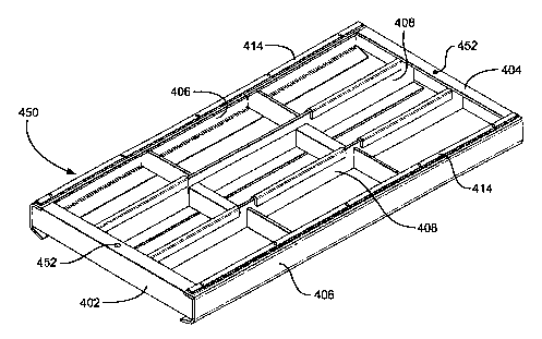
Figure 19 shows a mounting structure (or "tray") 400
for a shale shaker on which is releasably securable one
or more screen assemblies. As shown a screen assembly
mounts on and covers tray 400, but it is within the
scope of this invention to have a larger tray on which
two, three or more screen assemblies are secured or to
have multiple trays 400 on a single shale shaker (as, is
true for any tray or mounting structure in accordance
with the present invention disclosed herein). Although a
particular tray is shown in Figure 19, it is to be
understood that, in accordance with the present
invention, the teachings of the various holes and
projecting members for trays (for example, as in Figures
19-49) are applicable to known screen mounting
structures for shale shakers in which and on which the
holes and upstanding members may be used; and similarly
for the screen assemblies shown in Figures 20A - 48 the
various holes and projecting members may be used with
any suitable known screen assembly.
The tray 400 has two spaced-apart outer ends 402,
404 which are spaced-apart by sides 406. The entire
tray 400 is positioned in and connected to a basket or
other suitable enclosure or housing of a shale shaker.
Crossmembers 408 extend from end to end of the tray 400
and crossmembers 410, 412 extend between crossmembers 408
CA 02472692 2004-07-08
WO 03/061854 PCT/GB03/00166
- 28 -
and sides 406. A support member 409 extends beneath one
.of the crossmembers 408 (and such a support may be under
any crossmember). Wear strips 414 are connected to tops
of the sides 406 and wear strips 416 are on tops of some
of the interior crossmembers. An upstanding member 420
projects upwardly from each end 402, 404 of the tray
:400. Each upstanding member 420 is located, sized, and
configured for receipt within a corresponding hole of a
screen assembly placed on the tray 400. Fluid to be
treated by a shale shaker with a tray as in Figure 19 (or
-any tray disclosed herein) may flow across a screen
assembly placed on the tray in any desired direction; and
-one such direction is indicated by the arrows AA and BB
-in Figure 19.
Figures 20A to 20D show a screen assembly 430 in
accordance with the present invention which has a lower
support frame 432 (which may be any known screen
.assembly support frame or which may, alternatively, be
any known screen assembly support such as a strip
support, perforated plate, or unibody structure).
Screening material 434 (shown partially, but covering
the frame 432) is on the top of the frame 432 and may be
.any known screening material used in screen assemblies
for shale shakers, including, but not limited to, multi-
layer screen meshes and/or flat or 3-D materials. A
lower bar 436 is connected to or formed integrally of the
:frame 432 at each of its ends. Each end of the screen
assembly 430 has a hole 438 for receiving a member
projecting upwardly from a shale shaker's screen
mounting structure, for example, but not limited to, like
the upstanding members 420, Figure 19. The holes 438 do
not extend through the top of the frame 432. The lower
support frame 432 is rigid enough to inhibit the
screening material from curling and maintains the
screening material in substantially one flat plane. The
CA 02472692 2004-07-08
WO 03/061854 PCT/GB03/00166
- 29 -
support frame 432 is light and easy to handle. The
support frame 432 is preferably rigid enough to allow the
screening material 434 to be tensioned thereover and
glued or otherwise secured thereto and most preferably
rigid enough to be held at either end, whereupon the
screen assembly will not sag.
Figure 20E shows possible shapes 439a, b, c, d, e,
f, g, h, i and j as viewed from above, for any
upstanding member or upwardly projecting member in
accordance with the present invention, and also for
holes corresponding to such upstanding or upwardly
projecting members.
Figure 21 shows a tray 440 in accordance with the
present invention which is like the tray 400 (and like
parts are designated with the same numerals), Figure 19;
but which has three upstanding members 420 at each of
its ends, each for receipt within corresponding holes of
a screen assembly to be emplaced on the tray 400. Tray
ends or sides in accordance with the present invention
may have any desired number of upstanding or upwardldy
projecting members for receipt within corresponding
holes of a-screen assembly.
Figure 22 shows a tray 450 like the tray 400 (and
like parts are designated with the same numerals); but
without any upstanding members 420 and with a hole 452
in each of its ends. The holes 452 are located, sized,
and configured for receiving corresponding downwardly
projecting members of a screen assembly emplaced on the
tray 450.
Figures 23A to 23D show a screen assembly 460 in
accordance with the present invention like the screen
assembly 430, Figure 20A, and like numerals designate
like parts. Instead of holes 438, however, the screen
assembly 460 has downwardly projecting members 468 on
each of its ends. The downwardly projecting members 468
CA 02472692 2004-07-08
WO 03/061854 PCT/GB03/00166
- 30 -
are located, sized, and configured for receipt within
corresponding holes in a shale shaker's screen mounting
structure, for example, but not limited to, such as the
holes 452 in the support frame 432 shown in Figure 22.
Figure 24 shows a tray 470 in accordance with the
present invention like the trays 400 (Figure 19) and 450
(Figure 22); but with two upstanding members 472 at each
of its ends and a hole 474 in each of its ends. Each
upstanding member 472 is located, sized and configured
for receipt within a corresponding hole of a screen
assembly and the hole 474 is located, sized and
configured for receiving a corresponding downwardly
projecting member of a screen assembly. Either one -or
both of the upstanding members 472 may be deleted; there
may be three or more upstanding members 472; the hole
474 may be deleted; and/or there may be two, three or
more holes 474 - as is true for any tray in accordance
with the present invention.
Figures 25A to 25H show schematically shale shakers
in accordance with the present invention with shale
shaker decks (screen mounting structures) in accordance
with the present invention. The shale shakers of
Figures 25A to 25H are like the shale shaker of Figure
10B and like numerals designate the same parts. It is
within the scope of the present invention to employ any
of the holes or upstanding members in Figures 25A to 25H
on any shale shaker mounting structure disclosed herein.
Also, any screen assembly disclosed herein can have the
hole(s) and/or downwardly projecting members of the
screen assembly of Figure 25G. It is to be understood
that although the drawings of Figures 25A to 25H show
upstanding members or holes at only one side of a deck,
the other side (not shown) of the deck may have the same
structure, or it may have none of the structure shown.
A shale shaker 480 shown in Figure 25A has a
CA 02472692 2004-07-08
WO 03/061854 PCT/GB03/00166
- 31 -
plurality of spaced-apart holes 481, each hole for
receiving a corresponding downwardly projecting member
of a screen assembly placed on the shale shaker's deck.
The holes 481 extend down substantially perpendicularly
into the deck 122. Any number of holes 481 may be used
(one to four or more).
A shale shaker 482 shown in Figure 25B has a
plurality of spaced-apart holes 483, each hole for
receiving a corresponding downwardly projecting member
of a screen assembly placed on the shale shaker's deck.
The holes 483 extend down at an angle (toward the left)
into the deck 122. Any number of holes 483 may be used
(one to four or more) and they may extend into the deck
.122 at any desired angle, including, but not limited to,
angled toward or away from a fluid introduction end or
fluid exit end.
A shale shaker 484 shown in Figure 25C has a
plurality of spaced-apart holes 485, each hole for
receiving a corresponding downwardly projecting member
of a screen assembly placed on the shale shaker's deck.
The holes 485 extend down at an angle into the deck 122.
Any number of holes 485 may be used (one to four or
more) and they may be angled at any desired angle in any
desired direction.
A shale shaker 486 shown in Figure 25D has a
plurality of spaced-apart upstanding members 487, each
hole for receipt within a corresponding hole of a screen
assembly placed on the shale shaker's deck. The
upstanding members 487 extend up substantially
perpendicularly to the deck 122. Any number of members
487 may be used (one to four or more).
A shale shaker 488 shown in Figure 25E has a
plurality of spaced-apart upstanding members 489, each
for receipt within a corresponding hole of a screen
assembly placed on the shale shaker's deck. The
CA 02472692 2004-07-08
WO 03/061854 PCT/GB03/00166
- 32 -
upstanding members 489 extend up at an angle to the deck
122. Any number of members 489 may be used (one - four
or more) and they may project from the deck at any
desired angle in any desired direction.
A shale shaker 489 shown in Figure 25F has a
plurality of spaced-apart upstanding members 491, each
for receipt within a corresponding hole of a screen
assembly placed on the shale shaker's deck. The
upstanding members 491 extend up at an angle to the deck
122. Any number of upstanding members 491 may be used
(one - four or more) and they may be at any desired angle
in.any desired direction.
A shale shaker 492 shown in Figure 25H has a
plurality of spaced-apart holes 493, each hole for
receiving a corresponding downwardly projecting member
of a screen assembly placed on the shale shaker's deck
and a plurality of spaced-apart upstanding members 494
projecting up from the deck 122. The holes 493 extend
down substantially perpendicularly into the deck 122 (but
may be at any angle at any direction) and the upstanding
members 494 project up substantially perpendicularly to
the deck 122, but may be at any angle in any direction.
Any number of holes and/or upstanding members may be
used (one - four or more).
Figure 25G shows schematically a screen assembly 495
in accordance with the present invention, useful on a
shale shaker, which has a body or support 496 with two
spaced-apart downwardly projecting members 497 and two
spaced-apart holes 498. The downwardly projecting
members 497 are for receipt within corresponding holes
(for example but not limited to, such as the holes 493,
Figure 25H) in a shale shaker screen assembly mounting
structure; and the holes 498 are for receiving
corresponding upwardly projecting members of a shale
shaker mounting structure (for example, but not limited
CA 02472692 2004-07-08
WO 03/061854 PCT/GB03/00166
- 33 -
to, such as the upstanding members 494, Figure 25H).
Figure 26 shows a shale shaker 500 like the shale
shaker of Figure 9 (like numerals indicate the same
parts); but with a plurality of spaced-apart upwardly
projecting members 502 projecting up from the deck 92.
It is to be understood, although not shown, that as
desired, upstanding members 502 may be provided spaced-
apart on both sides or around the entire periphery of
the deck 92 (or of any shaker deck). Optionally, the
holes 93 may be deleted or they may be sized for
receiving downwardly projecting members of a screen
assembly.
Figure 27 shows a shale shaker 504 like that of
Figure 27 but with a plurality of spaced-apart upwardly.
projecting members 506 at the sides of the screen
assembly mounting structures of the shale shaker.
Optionally, the holes (or some of them) 72 and 73 may be.
deleted or they may be sized to receive a downwardly
projecting member of a screen assembly.
Figure 28 shows a wear strip 510 in accordance with
the present invention which has a body 511 and an
upstanding member 512 for receipt within a corresponding
hole of a screen assembly. Using openings 513 at either
end of the body 511, the wear strip 510 is connectible
to an end or side or crossmember of a shale shaker's
screen assembly mounting structure. Each opening 513
has, optionally, a bevelled edge 514 for ease of
installation, for example, but not limited to with
fasteners, bolts, screws, pins, and/or around upstanding
connectors on a shale shaker mounting structure. In
certain aspects the openings 513 are located so that the
wear strip 510 is slipped onto corresponding upstanding
members of a shale shaker mounting structure (for
example as in Figure 33). The wear strip (and any wear
strip herein) 510 may be made of any suitable material,
CA 02472692 2004-07-08
WO 03/061854 PCT/GB03/00166
- 34 -
for example, but not limited to fiberglass, rubber, zinc,
zinc alloy, urethane, BUNA-N, aluminum, aluminum alloy,
steel, stainless steel, wood, iron or plastic as may be
the upstanding member 512 (as may be any wear strip or
mounting structure disclosed herein).
Figure 29A and 29B show a wear strip 520 in
accordance with the present invention which has a body
521 and an upstanding member 522 for receipt within a
corresponding hole of a screen assembly. Using openings
523 at either end of the body 521, the wear strip 520'is-
connectible to an end or side or crossmember of a shale
shaker's screen assembly mounting structure. Each
opening 523 has, optionally, a bevelled edge 524 for
ease of installation, for example, but not limited to
with fasteners, bolts, screws, pins, and/or around
upstanding connectors on a shale shaker mounting
structure. In certain aspects the openings 523 are
located so that the wear strip 520 is slipped onto
corresponding upstanding members of a shale shaker,
mounting structure (for example as in Figure 33). The
wear strip (and any wear strip herein) 520 may be made =
of any suitable material, for example, but not limited
to fiberglass, rubber, steel, stainless steel, wood,
iron or plastic as may be the upstanding member 522.
Figure 30A and 30B show a wear strip 530 in
accordance with the present invention which has a body
531 and an upstanding member 532 for receipt within a
corresponding hole of a screen assembly. Using openings
533 at either end of the body 531, the wear strip 530 is
connectible to an end or side or crossmember of a shale
shaker's screen assembly mounting structure. Each
opening 533 has, optionally, a bevelled edge 534 for
ease of installation, for example, but not limited to
with fasteners, bolts, screws, pins, and/or around
upstanding connectors on a shale shaker mounting
CA 02472692 2004-07-08
WO 03/061854 PCT/GB03/00166
- 35 -
structure. In certain aspects the openings 533 are
located so that the wear strip 530 is slipped onto
corresponding upstanding members of a shale shaker
mounting structure (for example as in Figure 33). The
wear strip (and any wear strip herein) 530 may be made
of any suitable material, for example, but not limited
to fiberglass, rubber, steel, stainless steel, wood,
iron or plastic as may be the upstanding member 532. As
with any of the wear strips in Figures 28 to 32A, any
desired number of upstanding members of any desired shape
may be used. Also, any such upstanding member may be
formed integrally of or connected to a wear strip in
accordance with the present invention.
Figure 31A and 31B show a wear strip 540 in
accordance with the present invention which has a body
541 and an upstanding member 542 for receipt within a
corresponding hole of a screen assembly. Using openings
543 at either end of the body 541, the wear strip 540-is
connectible to an end or side or crossmember of a shale
shaker's screen assembly mounting structure. Each
opening 543 has, optionally, a bevelled edge 544 for
ease of installation, for example, but not limited to "
with fasteners, bolts, screws, pins, and/or around
upstanding connectors on a shale shaker mounting
structure. In certain aspects the openings 543 are
located so that the wear strip 540 is slipped onto
corresponding upstanding members of a shale shaker
mounting structure (for example as in Figure 33). The
wear strip (and any wear strip herein) 540 may be made
of any suitable material, for example, but not limited
to fiberglass, rubber, steel, stainless steel, wood,
iron or plastic as may be the upstanding member 542.
Figure 32A to 32C shows a wear strip 550 in
accordance with the present invention which has a body
551 and an upstanding member 552 (Figure 32B) or 557
CA 02472692 2004-07-08
WO 03/061854 PCT/GB03/00166
- 36 -
(Figure 32C) for receipt within a corresponding hole of
a screen assembly. Using openings 553 at either end of
the body 551, the wear strip 550 is connectible to an
end or side or crossmember of a shale shaker's screen
assembly mounting structure. Each opening 553 has,
optionally, a bevelled edge 554. Any upstandingmember
in any embodiment of the present invention may have a
rounded surface as does the upstanding member 557.
Figures 32D and 32E show wear strips with a hole at one
end and an opening at the other end. Figure 32D shows a
wear strip 550a like the wear strip 550, Figure 32A. The
wear strip 550a has a body 551a, like the body 551
described above, with an opening 553a, like the opening
553 described above and with an upstanding member 557a,
like the upstanding member 557 described above. The wear
strip 550a also has a hole 573a, like the hole 573
described below. Figure 32E shows a wear strip 550b like
the wear strip 550, Figure 32A. The wear strip 550b has
a-body 551b, like the body 551 described above, with an
opening 613a, like the opening 613 described below and
with an upstanding member 557b, like the upstanding
member 557 described above. The wear strip 550b also has
a hole 573b, like the hole 573 described below. The wear
strips of Figures 32D and 32E are emplaceable on a tray
with their end hole receiving an upstanding connector of
the tray and with their other end opening encompassing
another upstanding connector.
Figure 33 discloses a tray 560 like the tray 400,
Figure 21 and like numerals indicate the same parts.
Each end 402, 404 of the tray 560 has two spaced-apart
upstanding connectors 562 useful for releasably
attaching wear strips with appropriate openings (for
example, but not limited to, wear strips as in Figures
28 to 32C and 38A to 41A, with appropriately sized
openings) to the tray 560. Each connector 562 has a top
CA 02472692 2004-07-08
WO 03/061854 PCT/GB03/00166
- 37 -
564 larger than a base 565 so that, for example, upon
sliding an opening (for example, but not limited to an
opening 513 of the wear strip 510, Figure 28) around a
connector 562, the top 564 abuts a top surface of the
wear strip (which is made with an appropriate thickness)
thereby holding the wear strip in position. One, three
or more such connectors 562 may be used (with a
corresponding opening or openings in a wear strip).
Figures 34A and 34B show a wear strip 570 in
accordance with the present invention with a body 571 and
an upstanding member 572. Holes 573 at each end of the
body 571 may be used for fasteners, bolts, screws, or
pins to releasably secure the wear strip to a side of a
shale shaker mounting structure which has corresponding-,
15: holes for the fasteners, etc. Holes 573 (and any hole in
Figures 35A - 37A) may be bevelled as shown.
Figures 35A and 35B show a wear strip 580 in
accordance with the present invention with a body 581 and
an upstanding member 582. Holes 583 at each end of the
body 581 may be used for fasteners, bolts, screws, or
pins to releasably secure the wear strip to a side of a
shale shaker mounting structure which has corresponding
holes for the fasteners, etc.
Figures 36A and 36B show a wear strip 590 in
accordance with the present invention with a body 591 and
an upstanding member 592. Holes 593 at each end of the
body 591 may be used for fasteners, bolts, screws, or
pins to releasably secure the wear strip to a side of a
shale shaker mounting structure which has corresponding
holes for the fasteners, etc.
Figures 37A and 37B show a wear strip 600 in
accordance with the present invention with a body 601 and
an upstanding member 602. Holes 603 at each end of the
body 601 may be used for fasteners, bolts, screws, or
pins to releasably secure the wear strip to a side of a
CA 02472692 2004-07-08
WO 03/061854 PCT/GB03/00166
- 38 -
shale shaker mounting structure which has corresponding
holes for the fasteners, etc.
Figures 38A and 38B show a wear strip 610 in
accordance with the present invention which has a body
611 and an upstanding member 612 for receipt within a
corresponding hole of a screen assembly. Using holes
613 at either end of the body 611, the wear strip 610 is
connectible to an end or side or crossmember of a shale
shaker's screen assembly mounting structure. Each
opening 613 has, optionally, a bevelled edge portion 614
for ease of installation. A connector on a shaker tray
can be inserted through a generally round part 615 of
the openings 613 and then the wear strip is moved (to
the left in Figure 38A) to secure the wear strip in place
with the connectors.
Figures 39A and 39B show a wear strip 620 in
accordance with the present invention which has a body
621 and an upstanding member 622 for receipt within a
corresponding hole of a screen assembly. Using holes
623 at either end of the body 621, the wear strip 620 is
connectible to an end or side or crossmember of a shale
shaker's screen assembly mounting structure. Each
opening 623 has, optionally, a bevelled edge portion 624
for ease of installation. A connector on a shaker tray
can be inserted through a generally round part 625 of
the openings 623 and then the wear strip is moved (to
the left in Figure 39A) to secure the wear strip in place
with the connectors.
Figures 40A and 40B show a wear strip 630 in
accordance with the present invention which has a body
631 and an upstanding member 632 for receipt within a
corresponding hole of a screen assembly. Using holes
633 at either end of the body 631, the wear strip 630 is
connectible to an end or side or crossmember of a shale
shaker's screen assembly mounting structure. Each
CA 02472692 2004-07-08
WO 03/061854 PCT/GB03/00166
- 39 -
opening 633 has, optionally, a bevelled edge portion 634
for ease of installation. A connector on a shaker tray
can be inserted through a generally round part 635 of
the openings 633 and then the wear strip is moved (to
the left in Figure 40A) to secure the wear strip in place
with the connectors.
Figures 41A and 41B show a wear strip 640 in
accordance with the present invention which has a body
641 and an upstanding member 642 for receipt within a
corresponding hole of a screen assembly. Using holes
643 at either end of the body 641, the wear strip 640 is
connectible to an end or side or crossmember of a shale
shaker's screen assembly mounting structure. Each
opening 643 has, optionally, a bevelled edge portion 644
for ease of installation. A connector on a shaker tray
can be inserted through a generally round part 645 of
the openings 643 and then the wear strip is moved (to
the left in Figure 41A) to secure the wear strip in place
with the connectors.
Figure 42 shows a tray 650 in accordance with the
present invention for a screen assembly mounting
structure of a shale shaker like the tray 400, Figure
19, and like numerals indicate the same parts. The tray
650 has three holes 652 in each of its ends 402, 404.
(Note that fluid flow over a screen assembly on the tray
650, and on any similar tray, may be from the top side
406 in Figure 42 to the bottom side 406 in Figure 42; or
alternatively from end 402 to end 404). The holes 652
may be located, sized and configured for receipt therein
of corresponding downwardly projecting members of a
screen assembly or they may be used for releasably
connecting a wear strip in accordance with the present
invention to the tray 65 (or they may be used for
receiving fasteners that pass through a screen assembly,
as may be any hole in any tray in accordance with the
CA 02472692 2007-01-26
- 40 -
present invention).
Figure 43 show a tray 660 in accordance with the
present invention like the tray 400 of Figure 19 and
like numerals indicate the same parts. Sach end.402,
404 has on its top surface an amount 662 of releasably
cooperating hook-and-loop connection material and each
of two wear strips 664 has a corresponding amount 665
(see for example Figure 44) of suoh releasably
cooperating hook-and-loop connection material (for
example but not lim3ted to VELCRO material (for
releasably connecting the wear strips 664 to the tops of
the ends of tray 660. Each wear strip has an upstanding
member 667 (like the upstanding mamber 420, Figure 19).
The wear strips 664 are shoirn above the tray 400 over
the positions on the tray 664 at which they are connected
in use (as is true for the wear strips shown above the
tray in Figure 45).
. Figure 45 shons a tray 670 in..accordance with the
present invention like the tray 400 of Figure 1=9 and
like numerals indicate the same parts. Each end 402=,
404 has on its top surface an amount 672 of two-sided
adhesive tape for adhesively and releasably securing each
of two wear strips 674 to the tops of the ends of tray
670. Each wear strip 674 has an upstaading memnber 677
(like the upstanding member 420, Figure 19).
Figure 46 shoas a tray 680 in accordance with the
present invention like the tray 400, Figure 19, and like
numerals indicate the same parts. A wear strip 684 in
secured on crosememnbers 410, 412 as shoMn with any
suitable seeurement, fastener, adhesive, and/or welding.
it is aithiA the scope of thi.s invention to have a wear
strip in accordanoe with the present invention on any
crossinember or crossmembers of a shale shaker's screen
assembly mcunting structure.
Figure 47 shows a tray 690 in accordance with the
CA 02472692 2004-07-08
WO 03/061854 PCT/GB03/00166
- 41 -
present invention like the tray 400, Figure 19, and like
numerals indicate the same parts. A crossmember 412 has
an upstanding member 692 for receipt within a
corresponding hole of a screen assembly emplaced on the
tray 690. Another crossmember 412a has a hole 693 for
receiving a downwardly projecting member of a screen
assembly emplaced on the tray 690. Any number of holes
693 on any of the crossmembers may be used in accordance
with the present invention; and/or any number of
upstanding members 692 may be used on any of the
crossmembers. The hole 693 and upstanding member 692
may have any shape for holes and upstanding members,
respectively, disclosed herein.
Figure 48 shows a screen assembly 700 like the
screen assembly 430, Figure 20A, and like numerals
indicate the same parts. One crossmember 432a of the
frame 432 has a hole 703 sized, located and configured
for receiving a corresponding upstanding member of a
screen mounting structure of a shale shaker. A
crossmember 432b of the frame 432 has a projecting
member 702 for receipt within a corresponding hole in a
screen mounting structure of a shale shaker. Any number
of holes 703 may, in accordance with the present
invention, be used on a crossmember or crossmembers of
the frame 432; and/or any number of projecting members
702 may, according to the present invention, be used on
a crossmember or crossmembers of the frame 432.
Figure 49A shows a projecting member 710 in
accordance with the present invention which may be used
for any upstanding or upwardly projecting member or
downwardly projecting member disclosed herein. The
projecting member 710 has a base 712 larger than a top
714.
Figure 49B shows a hole 720 in material 722 which
has a top opening 724 larger than a hole bottom 726.
CA 02472692 2007-01-26
- 42 -
Sueh a hole may be used for any hole in any embodiment
of the present invention. The base 712 and top 714 (and
the top opening 724 and hole bottom 726) may be any
desired size, and the distance between them may be any
S desired length; and the shape of the top 714 and base 712
(and of the top openings 724 and hole bottom 726) may be
any shape dieclosed herein for an upstanding or upwardly
pro j ecting member.
Figures 50A and 50B show a screen assembly 730 in
accordance with the present invention which - has a
plurality of glued-together layers of screening material
731, 732, 733 with a plate 734 attached at one end and
secured to the lower layer 733 of screening material.
Ho1es 735 extend through the screening material layers
and through the plate 734. The plate 734 =anay -be
adhesively seeured to the screening material and/or any
suitable fastener and/or clanp apparatus may be used for
such seeurement. The holes 735 may be used (as may the
holes 743, Figure 50C) as holes for receiving an
upstanding member of a rcreen assembly mounting structure
of a shale shaker; or fasteners may be ineerted through
the holes to releasably secure the screen assmobly to a
shale shaker screen assembly mounting structure. As
with the glued-together layers of the screen assemblies
of Figures 50C, 50S and 50Q the screen assembly 730 may
be. any cvoaobinatiooa of two, three or more layers of
screening material and/or mesh as disclosed in U.S. Patent No.
6,669,985 issued December 30, 2003.
CA 02472692 2004-07-08
WO 03/061854 PCT/GB03/00166
- 43 -
Optionally, the screen assembly 730 has holes 736
through the screening material and through plates 737a,
737b; and, optionally, holes 738 through a plate 739.
It is within the scope of the present invention to
provide a hole or holes on the outer periphery of the
screen assembly 730 or to provide one or more holes with
a corresponding lower plate (made of any suitable
material including materials disclosed herein for wear
strips and projecting members, rigid or flexible) at an
inner area of the screen assembly 730 (and as may be
provided in the screen assemblies of Figures 50C and
50E).
Figures 50C and 50D show a screen assembly 740 in
accordance with the present invention which has a
plurality of glued-together layers of screening material
742 (like the layers 731 - 733, Figure 50B) and holes
743 through a plate 741 (like the plate 734, Figure 50B).
Optionally, a flexible seal flap 744 is provided along an
end (or side) of the screen assembly and it is within
the scope of the present invention to provide such a
flexible seal flap on the opposite side or end (or on
any side or end of any known screen assembly) for
sealing a screen-assembly-basket-wall interface when the
screen assembly is in position in a shale shaker basket.
A hook apparatus 745 is connected to one end (or side)
of the screen assembly 740 and provides a hook structure
that can be engaged by known screen mounting
apparatuses. With pins or fasteners extending through
the holes 743 to releasably connect the screen assembly
740 at one side of a screen basket, tension can be
applied to the screen assembly 740 through the hook
apparatus 745 for efficient tensioning and positioning
of the screen assembly on a shale shaker.
Figures 50E and 50F show a screen assembly 750 in
accordance with the present invention which has a
CA 02472692 2004-07-08
WO 03/061854 PCT/GB03/00166
- 44 -
plurality of glued-together layers of screening material
752 with plates 753, 754 on either side of the screen
assembly 750. Downwardly projecting members 755 (which
may be like any downwardly projecting members disclosed
herein) project down from the plates 753, 754 and are
sized, located, and configured for receipt in
corresponding holes of a screen assembly mounting
structure of a shale shaker.
Figure 50G shows a screen assembly 760 in accordance
with the present invention which has a plurality of
glued-together layers of screening material 762 (like
the layers 731 - 732, 742, and 752 disclosed above). An
outer peripheral layer 763 of glue, adhesive, and/or
epoxy surrounds the screen assembly 760 and a plurality
of spaced-apart holes 765 extend through the layer 763
and through the layers of screening material.,
(Alternatively the layers 763 and/or 764 may be made of,
material like that of any plate in Figures 50A - 50F.)
Optionally a layer 764 like the layer 763 is provided on~
the bottom of the screen assembly 760. Any one, two, or.
three sides of either layer 763, 764 may be deleted, for
example if holes are desired on less than all sides of
the screen assembly. A plate or plates (rigid or
flexible) may be positioned above layers of screening
material above any plate in Figures 50A - 50F.
Figure 51 shows a wear strip 770 (which may be any
wear strip in accordance with the present invention)
which is made in a bowed shape as shown in Figure 51 so
that it will exert an upward force on a screen assembly
mounted above it in a shale shaker. Alternatively, any
wear strip in accordance with the present invention which
is flexible may be connected to a shale shaker screen
assembly mounting structure so that it is bowed
upwardly. It is within the scope of the present
invention to employ an initially-bowed wear strip in a
CA 02472692 2004-07-08
WO 03/061854 PCT/GB03/00166
- 45-
flattened position so that in such flattened position it
exerts an upward force on a screen assembly above it.
This can be useful when wedges or other screen holding
items are used which are made of a material such as
rubber or urethane which can shrink or loose some of its
resiliency in use thereby loosening the mounting of a
screen assembly in a shale shaker.
The present invention, therefore, in some and not
necessarily all embodiments, provides mounting structure
for a shale shaker to which is releasably mountable a
screen assembly, the mounting structure having a body
over which a screen assembly is positionable, part of
material to be treated by the shale shaker flowable
through the body, at least one upwardly projecting member
projecting upwardly from the body, the at least one
upwardly projecting member sized and configured so it is
receivable in a corresponding hole in the screen
assembly.
The present invention, therefore, in some and not
necessarily all embodiments, provides mounting structure
for a shale shaker to which is releasably mountable. a
screen assembly, the mounting structure having a body
over which a screen assembly is positionable, part of
fluid to be treated by the shale shaker flowable through
the body, at least one hole in the body projecting down
into the body, the at least one hole sized and configured
for receiving a corresponding downwardly projecting
member of the screen assembly.
The present invention, therefore, in some and not
necessarily all embodiments, provides a wear strip (any
screen assembly mounting structure may have one, two,
three, four or more of them - for example, on two
opposite ends, on two opposite sides, and/or on one or
CA 02472692 2004-07-08
WO 03/061854 PCT/GB03/00166
- 46 -
more crossmembers) for attachment to a mounting structure
of a shale shaker to which is releasably mountable a
screen assembly, the wear strip having a body, at least
one upwardly projecting member projecting upwardly from
the body member, the at least one upwardly projecting
member sized, located and configured so it is receivable
in a corresponding hole in the screen assembly.
The present invention, therefore, in some and not
necessarily all embodiments, provides a screen assembly
for releasable mounting to a mounting structure of a
shale shaker, the screen assembly having one or more
screen holes as described herein and/or one or more
projecting members as described herein for mating with
corresponding hole(s) and/or projecting member(s) of a
screen mounting structure and/or a wear strip or wear
strips thereof of a shale shaker.
The present invention, therefore, in some and not
necessarily all embodiments, provides a shale shaker~
with: one, two, three or more screen assembly mounting
structures as described herein; one, two , three, four
or more wear strips as described herein; and/or one,
two, three or more screen assemblies as described herein;
and methods for their use.
The present invention, therefore, in some and not
necessarily all embodiments, provides a screen assembly
with a hole or holes in a surface of a support of a
screen assembly, for example, but not limited to in part
of a tubular frame of a screen assembly, and a
projecting member or members are moved into such hole or
holes (for example, a projecting member on a screen
assembly holding member or structure or on an air
bladder that is inflated above or below a screen
assembly to secure it in place on a shaker deck, bed or
tray). In certain such aspects the screen assemblies
shown in the drawings and described herein have the hole
CA 02472692 2004-07-08
WO 03/061854 PCT/GB03/00166
- 47 -
or holes in the topmost surface of a screen frame or
tubular support or in the bottom thereof.