Note: Descriptions are shown in the official language in which they were submitted.
CA 02472911 2004-07-06
' '
- CONTAINER WITH ELASTOMERIC LID SPRING
BACKGROUND OF THE INVENTION
The present invention relates to containers of the type
including a container body with an open mouth selectively
closed by a spring biased lid, and more particularly to such
containers wherein the biasing action is provided by a rubber-
like:.or elastomeric member mounted to and between the lid and
the xim portion of the container body.
The prior art includes many examples of lidded containers
wherein the closed lid, upon release of an appropriate latch,
automatically moves to an open position impelled by a biasing
spring. Such an opening force has, for the most part,
normally heretofore been provided by metal springs of various
types, including leaf or compression springs, torsion springs
and the like.
As a variation and improvement on conventional metal
springs, it has recently been proposed to use elastically
deformable springs such as rubber. Two examples 'of such usage
will be found in U.S. Patent No. 5,501,348, to Takeuchi, and
U.S. Patent No. 6,206,221 D1 to Bando et al. Takeuchi
utilizes a rather elaborately configured spring of L or
channel configuration, relying in large part on the
configuration for the spring action. Bando, to the contrary,
utilizes what appears to be a rather simple flat elongate
CA 02472911 2004-07-06
,. - .
constant thickness strip which, upon compression, curls on
itself and is received in an opening.
Another feature known in the prior art which has a
bearing on the present invention is the expedient of providing
a handle assembly on a container body wherein the body
inchides a vertical recess in a portion of the body wall with
the Dandle extending across the recess wherein the recess
allows for engaging fingers inward of the handle for
manipulation of the container. Note as an example U.S. Patent
No. Des.422,457 to Daenen et al and U.S. Patent No.
Des.423,294 to Klein. Also note U.S. Patent No. 6,318,586 D1
to Frankenberg.
SUMMARY OF THE INVENTION
It is a primary intention of the present inz-ention to
advance the art as described above in a significant manner,
particularly with regard to the use of rubber-like or
elastomeric springs. In doing so, it is intended that springs
in accord with the present invention provide, as compared with
the known prior art, not only a highly efficient spring
action, but also a spring which is both unique in structure
and in the manner of use and operation thereof. In
conjunction therewith, the present invention also proposes a
handle assembly which provides a practical handle for the
container body, particularly during the pouring of contents
therefrom, and cooperatively relates to the lid hinge assembly
2
CA 02472911 2004-07-06
so as to protectively and aesthetically enclose the hinge
assembly and elastomeric spring.
Referring initially to the container arid lid
relationship, the lid, through a hinge assembly, is pivotally
mounted to the container wall for free movement between a
closed position overlying the container mouth and an open
position upwardly swung from the container mouth to a
substantially vertical position. The container body,
vertically aligned with the hinge assembly and the open lid,
includes a recess defined in the wall thereof. In the
illustrated container embodiment, it will be noted that this
wall recess in fact comprises substantially the entire rear
wall of the container which, in conjunction with the narrow
front wall of the container and the wide side walls thereof,
present or form an oblong container, particularly desirable
where shelf space might be limited. The hinge assembly
includes a first component integral with the recessed wall or
wall portion for a minor portion of the upper end thereof.
This first hinge component is pivotally joined to a second
hinge component affixed or integral with the under surface of
the aligned portion of the lid. The container hinge component
is enclosed by the handle which extends from the opposed side
walls and transversely overlies the first hinge component in
outwardly spaced relation thereto, thereby concealing the
hinge component and defining a downwardly opening pocket or
3
CA 02472911 2004-07-06
compartment to receive the fingers of a hand, allowing an
upward lifting and manipulation of the container as desired.
The elastomeric spring, which~comprises a particularly
significant aspect of the invention, is distinct in its:
uniquely configured construction and in the particular
advantages derived therefrom. More specifically, the spring,
rather than being of a multi-angled configuration of webs, or
a sihgle flat constant thickness plate, is of what might be
considered a generally ellipsoidal shape with opposed planar
surfaces and both an elongate longitudinal cross-section which
can be broadly referred to as oval or elliptical, and a
transverse cross-section which is generally rectangular. More
specifically, the spring of the invention is formed with a
maximum thickness at the longitudinal central area thereof
with the thickness of the spring tapering outwardly to the
opposite sides of the central area to minimum thickness at the
two opposed ends of the spring which in turn are arcuately
formed. Thus, the thickness of the spring varies'at a
substantially constant rate from the center of the spring and
transversely across the width thereof, in a direction
longitudinally outward to the opposed ends, producing a spring
with the area of maximum bending moment at the central area
thereof which is also the area of maximum strength and, upon
elastic deformation, the area of maximum developed memory
induced force producing the desired lid opening action.
4
CA 02472911 2004-07-06
- The formation of the spring in this manner provides
significant advantages both with regard to the simplicity of
the structural configuration and in the~conse~rvation of
material and resultant economies. The variable thickness of
the spring provides for a concentration of the bulk of
material in the area of greatest value with only minimum
material being required and utilized toward the opposed
positioning and/or anchoring ends of the spring. The
formation of such springs with different force components
alloys for a concentration of the bulk of material within the
central area of maximum stress; as opposed to any teachings in
the constant thickness elastomeric springs heretofore
proposed.
In mounting the spring, the spring extends across the
pivot axis of the hinge assembly with the oppose. ends of the
spring retained against opposed abutments on the container and
lid with the orientation of the spring causing, upon a manual
closing of the lid to its latch pasition, a single folding of
,.
the spring at the central area thereof, the area of maximum
strength and elastic memory, to achieve the desired increase
of biasing force required to open the lid upon release
thereof. This simple single folding action is all that is
required, in conjunction with the unique configuration of the
spring, to provide a highly effective and efficient operation.
CA 02472911 2004-07-06
Other features, objects and advantages of the invention
will become apparent to those skilled in the art from the
following more detailed description of the invention.
BRIEF DESCRIPTION OF THE DRAWINGS
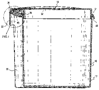
'Figure 1 is a front and side perspective view of the
upper portion of the container of the invention with the lid
closed;
Figure 2 is a view illustrating the container with the
lid ~-fully open;
Figure 3 is an exploded perspective view of the hinge
assembly with the spring removed;
Figure 4 is a rear perspective view of the container with
the Tid exploded and without the elastomeric spring;
Figure 5 is a detail similar to Figure 3 with the hinge
components engaged and with the spring mounted;
Figure 6 is a longitudinal cross-section view through the
closed container with the lid-opening spring in its fully
compressed position;
Figure 7 is an enlarged detail view of the area
designated in Figure 6 with the spring fully compressed;
Figure 8 is a similar view with the lid partially biased
open by the unfolding spring;
Figure 9 is a similar detail view with the spring fully
extended and the lid retained at its open position;
6
CA 02472911 2004-07-06
- Figure 10 is a perspective view of the elastomeric spring
of the invention illustrating the tapering configuration
thereof;
Figure 11 is a side elevation view of the spring
illustrating both the taper and the preferred symmetry
thereof;
.Figure 12 is a transverse cross-sectional view taken
substantially on a plane passing along line 12-12 in Figure
10; and
;Figure 13 is a longitudinal cross-sectional view taken
substantially on a plane passing along line 13-13 in Figure
10.
DESCRIPTION OF PREFERRED EMBODIMENT
Referring now more specifically to the draw~.ngs, the
container l0, which for purposes of illustration has been
presented as an elongate rectangular canister, includes a
container body 12 and a container lid 14 pivotally mounted to
the body for selectively closing the container mouth. In the
illustrated embodiment, the container body 12 includes wide
side walls 16 and relatively narrower front and rear walls 18
and 20.
The rear wall 20, note Figures 2 and 4, is inwardly
arcuately recessed for at least a major portion of the height
and width thereof. An arcuate handle 22, integral with the
opposed side walls 16, arcs transversely across the rear wall
7
CA 02472911 2004-07-06
recess for a minor portion of the height of the recess at the
upper end thereof. Thus formed and positioned, the container
can be easily lifted by the handle by engaging~one's fingers
about the handle and upwardly into the compartment or pocket
formed between the handle and recess.
The hinge assembly, that is the means by which the lid is
pivotally mounted to the container body, is protectively
enclosed and concealed within the formed handle pocket
upwardly~spaced from the lower edge of the handle. Noting
Figures 3 and 4 in particular, a pair of laterally spaced
rearwardly directed support arms 24 are integrally formed with
the recessed rear wall portion and extend rearwardly
therefrom, each terminating in a laterally outwardly directed
short pivot pin 26 which combine to define the pivot axis for
the lid.
Each pivot pin 26 is rotatably received within a socket
or bearing aperture 28, only one of which is shown, defined in
a pair of laterally spaced partitions or mounting blocks 30
integral with and depending from the top panel 32 of the lid.
As desired, the pin support arms 24 can include a small degree
of flexibility to allow for a snap mounting of the lid to the
container body. Noting Figures 3 and 5, the lid 14, at the
hinge assembly, will also include an integral arcuate
depending wall 34 which, upon a closing of the lid, seats just
inwardly of the arcuate or recessed rear wall 20 of the
container body for preventing any accidental discharge of
8
CA 02472911 2004-07-06
contents from the container body with the lid fully closed. A
similar shorter lid rear wall 36, which will tend to stabilize
the partitions or mounting blocks 30~iahich receive the pivot
pins 26, also depends from the lid top panel 32 along an
arcuate curvature corresponding to that of the handle 22 and
lays~immediately inward thereof in the closed position of the
lid~as noted in Figures 6 and 7. This rear wall, noting
Figure 6 in order to allow fox free movement of the lid 14
without interference with the pivot pin support arms 24, can,
if necessary, have a pair of recesses 38 therein aligned with
the arms 24.
Of particular significance with regard to the present
invention is the manner in which provision is made for the
spring biased opening of the lid away from the container rim
which defines the mouth of the container. This is achieved
utilizing a highly unique although structurally simple spring
or spring unit 40 detailed in Figures 10-13. The spring 40 is
formed of an appropriate elastomer or rubber-like material,
preferably silicone and, while the size can vary, may as an
example be 30 mm long and 10 mm thick at its widest position
for use with a container of the type illustrated herein with a
general capacity of approximately 1.7 liters. The
configuration of the spring 40 is what might be considered
elliptical or oval in longitudinal cross section with a
central area of maximum thickness. The spring arcuately
tapers to opposed ends of minimum thickness, preferably at a
9
CA 02472911 2004-07-06
constant and equal rate toward the opposite ends along opposed
or upper and lower arcing surfaces. The opposed ends 42 of
the spring are rounded and the~opposed sides~~or side faces 44
are flat. The spring, so formed and with the ends retained as
illustrated, is intended to fold in half with the bend at the
maximum thickness central area wherein the greatest strength
and,bending moment occurs for maximum simplicity and
efficiency.
Noting Figure 9 in particular, the spring 40 can easily
snap..':..into position within the hinge area extending across the
pivot axis between the support arms 24 with a first or
container end of the spring seated on a ledge 46 integral with
and extending rearward from the rear wall 20 and both abutted
against the rear wall 20 and nested within a corner defined
between the rear wall 20 and the inner end of the ledge 46.
The second or lid end of the spring 40 similarly engages
against an inwardly extending shoulder or abutment 48 integral
with and extending from the lid top panel 32 with the
corresponding end of the spring 40 nested within the corner
defined between the top panel 32 and shoulder 48. The spring
is stable in this substantially unstressed position and is
retained, generally without elastic deformation, nested at the
opposed ends thereof. The stabilization of the spring 40 in
this position may be enhanced by a positioning abutment or
wall 50 which projects from the undersurface of the lid panel
32 and engages. the spring generally at the widest central area
CA 02472911 2004-07-06
. thereof. In this fully open position of the lid, it will be
noted that the rear depending wall 36 of the lid can also
engage and encourage both a retention of the~~spring 40 and a
complementary retention of the lid in an upright fully open
position. Any tendency of the lid to freely move from the
open.'.position in either direction will be effectively resisted
by the inherent strength of the spring itself which requires a
positive manual force to compress from its at rest position.
Noting the sequential steps of Figures 8 and 7, as the
lid ~s moved to its closed position, a manual downward
pivoting of the lid, against the biasing force of the spring
40, will move the abutment wall 50 of the lid relatively
rearward and allow for a central folding of the spring 40
rearward as the upper portion of the spring folds downward
with the actual bending occurring at the wide cer..tral area of
the spring. This folding action is encouraged by the shoulder
48 and by the upper rim area of the rear wall 20 above ledge
46 both of which generally engage the forward face of spring
40 and prevent any tendency for the spring to fold forwardly.
A simple single fold action results and a maximum biasing or
elastic memory force is developed which, upon release of the
lid, causes the lid to spring upwardly and rearwardly to its
open position, at which point the lid is stabilized by the
inherent strength of the spring in its unbiased condition, or
possibly by a slight compressive force retained within the
spring. It is also to be appreciated that the forming of the
11
CA 02472911 2004-07-06
. pivot axis by two spaced pivot pins allows for the positioning
and folding of the spring directly at the pivot axis in a
compact manner and in a manner~~which achieved maximum
efficiency.
As will be recognized, any appropriate latch mechanism
can.be used to retain the lid closed against the biasing force
of tie spring. For example, as illustrated in Figures 1 and
6, the front wall 18 of the container body can be provided, at
j,.
the:~im of the container with a locking projection or abutment
51 'rich snap locks within the aperture of a depending latch
52 extending from the forward end of the lid 14. Release of
the latch will require only a slight forward and upward
flexing thereof so as to free the abutment, at which point the
lid will move smoothly to its fully open position.
The foregoing is illustrative of the principles of the
invention; and while a specific embodiment of the invention
has been set forth in detail, it is to be appreciated that
variations may occur to those skilled in the art, such as
dimensional changes resulting in both larger and smaller
containers, and containers of shapes other than the basic oval
shape illustrated, all without departing from the spirit and
scope of the invention as set forth in the following claims.
12 '