Note: Descriptions are shown in the official language in which they were submitted.
CA 02473316 2004-07-09
CASTING SYSTEM AND METHOD FOR POURING
NONFERROUS METAL MOLTEN MASSES
Background of the Invention:
Field of the Invention:
The present invention relates to a casting system for the
pouring of nonferrous metal melts, in particular copper or
copper alloys, for the manufacture of slab-type products. The
system has a tundish with at least one submerged pipe,
preferably in an inclined disposition, that submerges into a
molten bath inside a thin-slab mold. The invention further
pertains to a pouring method.
Submerged pouring pipes for discharging molten metal into a
mold are well-known in various styles and designs. Submerged
pouring pipes are intended to ensure an even and turbulence-
free distribution of molten metal inside the mold. Also, the
use of submerged pipes is meant to prevent oxygen in the air
from coming in contact with the metal flow underneath the bath
surface. Caused by the hydrostatic pressure in the tundish the
molten mass is accelerated to the required flow rate, and the
flow rate as such increases as a function of the pouring
angle. In practice, submerged pouring pipe applications show
that with increasing acceleration a negative pressure builds
-1-
CA 02473316 2004-07-09
WBT-103
up in the submerged pipe which creates turbulent movements in
the melt inside the mold and, as a consequence, causes bath
level fluctuations. In addition, the casting of metal masses,
in particular if copper or copper alloy is involved, is
accompanied by a number ¾f chemical and physical processes,
including most intensive interaction between the gaseous and
solid component parts of the melt. These boundary conditions
or constraints are influenced, among other things, by the
temperature gradient and the pressure of the molten mass.
Negative pressures, as they may build up in the submerged
pouring pipe, can lead to a release of the gaseous substances,
such as hydrogen, sulphur dioxide, contained in the melt. In
case of release of gases there is the risk that porous areas
develop when the melt solidifies, which will diminish the
quality of the finished product.
To prevent negative streaming pressures to build up in the
pouring pipe, German published patent application DE 40 34 652
Al suggests the cross section at the inlet end of the pouring
pipe, by installing a throat, to be kept smaller than the
cross section of the effective area of flow at the discharge
end, with a view to building up in the molten stream a
pressure higher than the atmospheric pressure. The outlet of
the metallurgic vessel and the pouring pipe are connected to
each other by a conical set of seals.
-2-
CA 02473316 2004-07-09
WBT-103
German patent DE 197 38 385 C2 describes an submerged pouring
pipe which has at its lower end a bottom element together with
at least two lateral discharge openings arranged above the
bottom element. The internal wall of the submerged pipe is
equipped with special flpw-guiding elements.
From German published patent application DE 101 13 026 Al,
there is known a submerged pouring pipe with a funnel-type
swirl chamber arranged at the end of the pipe, with a stalled
edge provided at the part connecting pipe section with a swirl
chamber.
European patent EP 0 925 132 B1, describes a submerged pouring
pipe for continuous casting of thin slabs where the pipe as
such, with a circular cross section, is arranged in vertical
position connected with the foundry ladle. The pouring pipe
has at its lower end a flattened distribution section, a so-
called diffuser, to submerge into the molten mass in the mold.
Inside the diffuser there is a separation body tapering in
flow direction so as to form two part streams. The diffuser's
cross section above the separating body is smaller than the
cross section of the upper section of the pouring pipe.
The side walls of the diffuser diverge outwards at the same
angle as the side walls of the separating body diverge
inwards. This design is meant to prevent turbulences and other
-3-
CA 02473316 2004-07-09
WBT-103
whirling motion in the bath surface. The disadvantage in this
arrangement is that the stream of molten mass is still
discharged deep into the mold bath and, hence, degassing takes
place in the internal areas of the mold bath. Submerged
pouring pipes as are known from the state of the art described
above are designed for use in vertical pouring, in particular
of steel melts, for relatively thick slabs. The stream of
molten material is injected in vertical direction, i.e. on the
shortest possible way into the mold bath. As a rule, the
stream is left undisturbed by technical means until short
before entering the mold bath.
Summary of the Invention:
It is accordingly an object of the invention to provide a
method and a system of casting a non-ferrous melt which
overcomes the above-mentioned disadvantages of the heretofore-
known devices and methods of this general type and which
provides a casting system for pouring nonferrous metal molten
masses, in particular copper or copper alloys, that ensures a
trouble-free injection of the melt into the mold together with
the degassing to take place at the exposed surface of the
mold, which prevents negative pressures from building up in
the submerged pipe, and which is further distinguished by a
simple structural design. It is a further object to provide a
suitable method for pouring nonferrous metal molten masses.
-4-
CA 02473316 2004-07-09
WBT-103
With the foregoing and other objects in view there is
provided, in accordance with the invention, a casting system
for pouring nonferrous metal melt, in particular copper or
copper alloy. The system comprises:
a tundish and at least one submerged pipe communicating with
the tundish and extending at an incline with a pre-defined
pouring angle towards and into a mold;
the submerged pipe having a first section and a second section
defining a tip nozzle for submersion into a molten bath in the
mold, whereby the tip nozzle is sealed off at a free end
thereof, the second section having a wall facing a bottom side
of the mold formed with at least one discharge opening and
configured to effect a first change in a flow direction of a
molten mass through the submerged pipe; and
a lip disposed at the tip nozzle, overlapping the discharge
opening at a pre-defined distance, and causing the molten mass
to experience a second change in the flow direction and
distribution transversely to a longitudinal axis of the mold,
and the discharge opening together with the lip being located
below a mold bath surface in an operating state thereof.
The novel casting system is configured so as to allow the
molten mass in the tundish to flow, preferably in a sloping
-5-
CA 02473316 2004-07-09
WBT-103
way, downwards in into the mold that is placed at a
geodetically lower level.
The pouring angle can be from 2 to 900. At the front side of
the tundish, as seen in discharge direction, there is at least
one submerged pipe sloping downward at the specified pouring
angle. In order to be able to pour slab-type products of a
wider size, i.e. the width of which is greater or equal 1.5 H
(H being the height or the thickness, respectively), the
tundish may be equipped with more than one submerged pipe, all
of them being of identical design and incorporated one next to
the other at a specified spacing.
The submerged pipe comprises a first section with its internal
walls gradually narrowing in flow direction of the molten
mass, and a second section forming the submerged pipe's tip
nozzle. The internal wall of the first section has not
necessarily to be of a tapering shape but can have other
suitable geometrical forms. In case of need, there can be a
short tubular connecting piece right at the and of the first
section before the latter is changing over to the throat. This
connecting piece, or the starting piece of the first section
is cast-in into an insert made of refractory concrete arranged
in the tundish. The first section, starting at the tundish,
extends as far as the very surface of the mold bath. Caused by
the throat, the cross section changes to a smaller effective
-6-
CA 02473316 2004-07-09
WBT-103
area. Tapering can be achieved on different ways. Starting
with a circular cross section at the beginning of this
section, the pipe may be squeezed, for example, into a flat
shape where the cross-sectional area at the end of this
section appears to be a Jong hole. Such re-forming may be done
in a way by which the cross-sectional area at the end of the
section has an elliptical shape, or the entire section may be
formed to taper in a hexagonal style. In another version this
section may be formed in a conical shape. This section is
followed by the submerged pipe's tip nozzle that submerges
into the bath of molten mass inside the mold. At its free end,
the tip nozzle is sealed off, e.g. by a plug. At its wall
facing the bottom side of mold, the tip nozzle has at least on
discharge opening which, in operating state, is situated in
the mold bath in a subsurface position and as such causes the
stream of molten mass to undergo a first deflection.
The submerged pipe may be made as a whole from one single pipe
section where the tip nozzle of the submerged pipe may be
reformed in the same way as the upstream pipe section so as to
have at its end an elliptical or circular cross-sectional
area, or a cross-sectional area in the shape of a oblong hole.
Hence, the shape of the cross-sectional area, seen over the
overall length of the tip nozzle of the submerged pipe, does
change only slightly.
-7-
CA 02473316 2004-07-09
WBT-103
Another option is to configure the tip nozzle as a separate
component that has an almost constant or tapering cross-
sectional area, and to attach the separate component to the
re-formed section, for example, by welding. In such case it is
possible to build the se-ction in a conical shape and attach to
it the submerged pipe's tip nozzle that is shaped as a long
hole, with the submerged pipe's tip nozzle being provided with
a short transition piece to connect the circular cross section
with the long-hole one. The submerged pipe's tip nozzle when
built as a separate component may be made of any heat-
resistant material other than used for the tapering section.
If the tip nozzle cross section is shaped as an oblong hole
the distance between the two opposite parallel wall sections,
should be at least one third of the cross-sectional diameter
as determined at the beginning of the tapering section of the
submerged pipe.
The discharge opening, through which the molten mass may flow
out, provided at the bottom part of the tip nozzle is
preferably formed in oblong hole shape. Instead of such an
oblong hole, there may be two circular openings placed right
behind each other.
As the first section of the submerged pipe has a gradually
narrowing cross section the melt is kept in constant contact
-8-
CA 02473316 2004-07-09
WBT-103
with the internal walls of the submerged pipe so as not to
allow any air bubbles or caves to be formed inside the
submerged pipe. Length and grade of tapering in this section
is dependent of the properties of the molten mass and the
pouring angle selected. Submerged pipes are of constant wall
thickness.
As the tip nozzle is sealed off and the molten mass is not
allowed to flow out there in axial direction, the stream of
molten mass, when approaching the discharge opening(s),
undergoes a first deflection by at least 90 in relation to
the pouring angle. This change of direction which is forced
upon the stream of molten mass is of importance as this will
ensure the molten mass is discharged into the mold as gently
as possible. Preferably, cross-sectional area of the discharge
opening, or the total of the cross-sectional areas of all
discharge openings involved should be from 80% to 98% of the
cross-sectional area as measured at the end of the tip nozzle.
In certain applications, this value can be even greater than
100%. The cross-sectional areas of the discharge openings may
be of different shapes. In operating conditions, the submerged
pipe is completely filled up with molten mass which, over the
entire pouring process, is not allowed to get out of contact
with the submerged pipe's internal walls. This in turn rules
out the risk of negative pressures to build up so as to not
allow any unwanted degassing to occur in the melt. By the
-9-
CA 02473316 2004-07-09
WBT-103
deflection, or change of direction of the stream of molten
mass as provided when entering the molten bath a so-called
"shooting" of molten mass is avoided and, hence, excessive
formation of bubbles is prevented.
As another important feature there is a lip spaced out
underneath the discharge opening(s) from where the lip is
overlapping the opening(s) by which the stream of molten mass
is forced into a second change of direction. The lip is sized
so as to provide an impact area equal or greater than that of
the discharge opening. The lip is arranged parallel or slanted
to the discharge opening in a pre-defined distance which
preferably should be at least 5 mm. In case of slanted
arrangement the greatest distance should be at least 5 mm. In
operating state, both the discharge openings and the lip are
found in the molten bath inside the mold in a subsurface
position.
The molten mass that flows out from the discharge opening
streams, in a first step, flows against the lip where it is
slowed down, and is again deflected by at least 900 so as to
be distributed in lateral direction in the molten bath. The
said second change of direction makes the insertion of melt
into the mold to be in a most gentle way. Parting the molten
mass when flowing against the lip into two part streams
leaving in lateral direction favors possibly still existing
-10-
CA 02473316 2004-07-09
WBT-103
bubbles wandering up to the molten bath surface in the mold.
Practical tests showed that the above measures make it
possible to reduce the flow rate of the molten mass at the
entrance into the molten bath to a speed equal or less than
0.5 meters per second. ,'
With the above and other objects in view there is also
provided, in accordance with the invention, a method for
pouring nonferrous metal molten mass, such as copper or copper
alloy melt. The method comprises:
guiding the metal melt from a tundish, through a submerged
pipe that extends at a pre-defined pouring angle, and into a
molten bath of a mold;
significantly reducing an increasing flow rate of the molten
mass by effecting at least two changes in a flow direction of
the molten mass, by twice deflecting a flow of the molten mass
with at least 90 deflections, and in a subsurface region
inside the molten bath of the mold.
In other words, it is primarily important that the flow rate
of molten mass, which increases as a function of the pouring
angle, is reduced inside the submerged pipe and slowed down
before being injected into the molten bath in the mold. Also,
the direction of flow of the stream of molten mass is
deflected at least twice by at least 90 .
-11-
CA 02473316 2004-07-09
WBT-103
This combination of twice changing the direction of flow of
the stream of molten mass before it is discharged into the
molten bath results in a significant reduction of the flow
rate, being approximately 50%.
Due to the lateral - transversely relative to the longitudinal
axis of the mold - discharge of melt separated into two part
streams, the melt situated near the mold walls is constantly
kept in contact with fresh hot molten masses and, as a
consequence, cannot form surface films of solidified material.
Furthermore, hot molten masses are prevented from flowing
straight against the mold's internal walls. Gas bubbles
possibly still contained are allowed to escape right at the
mold's internal walls.
The measures according to this invention lead to a
significantly improved microstructure of the semi-finished
products that are being manufactured. Undesirable gas or air
inclusions are avoided. Due to the repeated change in the
direction of flow of the stream of molten mass before it is
discharged into the molten bath, which results in a
significant reduction of the flow rate, damages to the mold's
internal walls are avoided to a very large extent.
-12-
CA 02473316 2004-07-09
WBT-103
The tapering section as well as the tip nozzle of the
submerged pipe are made preferably from one and the same heat-
resistant material but can also be made from different
materials such as, for example, a combination of ceramic and
metal. For start-up purp4bses it may be advantageous to have
the submerged pipe equipped with an additional heating
assembly, e.g. a resistance heating.
The proposed casting system can be used for pouring thin-
walled strips of nonferrous metal, in particular copper or
copper alloy, achieving superior quality levels.
In a vertical configuration of submerged pipes the tip nozzles
of the submerged pipes have at least two discharge openings on
opposite sides, either of which is overlapped by a spaced lip
so as to twice deflecting the stream of molten mass by at
least 90 , and reducing its flow rate significantly before
discharging the molten mass into the mold bath.
Once more in summary, starting from the disadvantages of the
prior art, a casting system is created that guarantees a
trouble-free discharge of the molten mass into the mold as
well as its degassing at the exposed surface of the mold. The
solution provided herein is a casting system consisting of a
tundish with at least one submerged pipe attached to the same,
preferably in an inclined arrangement at a pre-defined pouring
-13-
CA 02473316 2004-07-09
WBT-103
angle, with a first section and a second section comprising
the tip nozzle of the submerged pipe to submerge into the
molten bath inside a mold. The tip nozzle of the submerged
pipe is sealed off at its free end has at its wall facing the
mold's bottom side at least one discharge opening to effect a
first change in the direction of flow of the stream of molten
mass. At the tip nozzle of the submerged pipe there is a lip
spaced out so as to overlap the discharge opening which leads
to a second change of the direction of flow of the stream of
molten mass together with its lateral distribution seen from
the mold's longitudinal axis, with both the discharge opening
and the lip in operating state being situated inside the mold
bath in a subsurface position.
Other features which are considered as characteristic for the
invention are set forth in the appended claims.
Although the invention is illustrated and described herein as
embodied in a casting system and method for pouring nonferrous
metal molten masses, it is nevertheless not intended to be
limited to the details shown, since various modifications and
structural changes may be made therein without departing from
the spirit of the invention and within the scope and range of
equivalents of the claims.
-14-
CA 02473316 2004-07-09
WBT-103
The construction and method of operation of the invention,
however, together with additional objects and advantages
thereof will be best understood from the following description
of specific embodiments when read in connection with the
accompanying drawings.
Brief Description of the Drawings:
Fig. 1 is a simplified view of a longitudinal section through
a casting system according to the invention;
Fig. 2 is a perspective view of a first modification of the
submerged pipe;
Fig. 3 is an enlarged view of the detail "X" in Fig. 2;
Fig. 4 is an enlarged front view of the submerged pipe
according to Fig. 2;
Fig. 5 is a perspective view of a second modification of the
submerged pipe;
Fig. 6 is a longitudinal section of the tip nozzle of a
submerged pipe according to the invention in inclined
configuration;
-15-
CA 02473316 2004-07-09
WBT-103
Fig. 7 is a perspective view of a tip nozzle of a submerged
pipe with an integrally formed lip, forming a separate
component part; and
Fig. 8 is an isometric view of an assembly of several
submerged pipes with electric resistance heating.
Description of the Preferred Embodiments:
Referring now to the figures of the drawing in detail and
first, particularly, to Fig. 1 thereof, there is shown a
casting system for pouring copper strips using a mold for
continuous casting, also known as "casting with traveling
mold." After the copper is melted, the molten mass run from
the melting furnace into the tundish 1 which, in this example,
is equipped with a casting snout 2. Depending on the width of
the strip to be poured the casting snout 2 may have several
identical submerged pipes 6, e.g. 6, 8, or 10, arranged next
to each other in a pre-defined pouring angle of approx. 10 .
The individual submerged pipes' 6 spacing can vary. The view
in Fig. 1 shows only one submerged pipe 6. The submerged pipes
6 have cylindrical connecting pieces 7 (cf. Fig. 2) that are
cast-in into an insert made of refractory concrete that forms
part of the tundish 1. The mold 3 is located between the
traveling mold top band 4 and the traveling mold bottom band 5
which are both tensioned using deflection pulleys and driving
rollers. Fig. 1 only shows the two deflection front pulleys
-16-
CA 02473316 2004-07-09
WBT-103
4a, 5a. Also, the mold's side and rear walls, which can be as
high as 70 mm, are not to be seen in that drawing. The casting
system is integral part of a unit for continuous manufacture
of copper strips. The line marked with an "X" is the
longitudinal centre axis,'of mold 3. The molten copper
contained in the tundish 1 flows, forced by the inherent
hydrostatic pressure, through the submerged pipes 6 into the
mold 3. The flow rate of the molten copper is influenced by
the inclined arrangement of the submerged pipes 6 and the
predetermined pouring angle as is required by the process.
Right after the relatively short connecting piece 7 with
circular cross section there begins the submerged pipe's 6
section 8 that gradually narrows in flow direction and extends
from the casting snout 2 as far as a bath surface 15 in the
mold 3. In the operating position, the front part of the
submerged pipe 6, that is the tip nozzle 9 of the submerged
pipe, completely submerges into the molten bath in the mold 3.
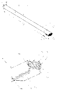
Fig. 2 shows a first modification of the submerged pipe 6 as a
separate component part in magnified form. The submerged pipe
6 has a cylindrical connecting piece 7 which is, seen in flow
direction, followed by a gradually narrowing section 8 the
diameter of which measured right at the beginning being D1
which is identical to that of the connecting piece 7. The
section 8, the length of which being Ll, is followed by the
-17-
CA 02473316 2004-07-09
WBT-103
tip nozzle 9 of the submerged pipe the length of which being
L2. The L1-to-L2 ratio is 8.3, for example. The connecting
piece 7, the section 8 and the tip nozzle 9 of the submerged
pipe are manufactured from a tubular pipe section made of
heat-resistant material that is squeezed by means of a tool
into a continuously flattening shape in the area where the
section 8 and the tip nozzle 9 of the submerged pipe meet. At
the beginning, the section 8 has a circular cross section D1
which, seen in flow direction, becomes more and more flat as
being reformed in one plane so as to terminate in a pre-
defined long-hole shape that emerges at the end of the tip
nozzle 9 of the submerged pipe (cf. Fig. 4). Such re-forming
produces a gradually narrowing, i.e. a change in cross section
along with a reduction of cross-sectional area. The cross-
sectional area as it measures at the end of the tip nozzle 9
of the submerged pipe is smaller by approx. one third than the
cross-sectional area with diameter Dl at the beginning of the
section 8. The long hole 10 as is formed at the end of the tip
nozzle 9 of the submerged pipe is closed by a welded plug 11
or in any other convenient way. As can be clearly seen in Fig.
3, the long hole 10 is formed by two parallel wall sections
10a, 10b running straight on opposite sides and two
semicircular wall sections 10c, 10d, where the distance
between the two straight running wall sections 10a, 10b is at
least one third of the diameter D1 in the section 8, in this
example being approximately 10 mm.
-18-
CA 02473316 2004-07-09
WBT-103
In the even wall section 10a of the tip nozzle 9 of the
submerged pipe that faces the mold bottom band 5 in
operational state there is an oblong hole-type discharge
opening 12 for the molteh copper to flow out. Practical
experiments have shown that it is advantageous for the cross
sectional area of those openings to total preferably 90% or
98% of the cross section of flow as it measures at the end of
the tip nozzle 9 of the submerged pipe. Instead of such a long
hole 12 there can be two circular discharge openings 12a, 12b
arranged right behind each other, as is shown in Fig. 7.
The discharge openings 12, 12a, 12b are "overlapped" by a
parallel lip 13, where "overlapping" in this case means that
the width of the lip 13 is equal or greater than the open
width of the long hole 12, or greater than the diameter in
case of circular discharge openings. In the modification
according to Fig. 3, the lip 13, together with its spacers
13a, is welded to the tip nozzle 9 of the submerged pipe. The
free space between the discharge opening 12 and the lip 13
should be 5 mm minimum.
Fig. 5 shows another modification of a submerged pipe 6a, in
which the section 8 as well as the tip nozzle 9 of the
submerged pipe are conically shaped over their entire length,
starting with diameter D1 that is continuously reduced, by
-19-
CA 02473316 2004-07-09
WBT-103
reducing the circular cross-sectional area, to diameter D2 at
the end of the tip nozzle 9 of the submerged pipe. The
circular opening of the tip nozzle 9 of the submerged pipe is
sealed with the plug 11. The difference between the diameter
Dl and diameter D2 is 45,'0. The discharge opening for the
molten mass to flow out and the lip 13 are of the same design
as used in the modification shown in Fig. 2. Compared with the
submerged pipe as shown in Fig. 2 this one has no separate
connecting piece. In the tip nozzle 9 of the submerged pipe
shown in Fig. 6 the lip 13 overlapping the discharge opening
12 is provided in an inclined arrangement. Using a spacer 13a,
the lip 13 being arranged in a distance of 5 mm to the wall of
the submerged pipe's tip nozzle runs diagonally upwards up to
the end of the submerged pipe's tip nozzle. The lip 13 is
welded onto the submerged pipe's tip nozzle. For the rest,
this tip nozzle is provided similar to the tip nozzle of the
submerged pipe shown in Fig. 2.
Fig. 7 shows a tip nozzle 9a of a submerged pipe in form of a
separate component part that can be attached, and welded in
place at the end of the conical section of a submerged pipe
according to the modification as shown in Fig. 5. The tip
nozzle 9 of the submerged pipe has a constant cross section in
form of an oblong hole 10, the downstream end of which is
sealed with a plug 11. On the opposite side, the tip nozzle 9a
of the submerged pipe has a transition piece 14 to provide the
-20-
CA 02473316 2004-07-09
WBT-103
change-over from the long-hole shape into the circular shape,
exactly matching the appropriate section of the submerged
pipe 6. At the bottom side of the tip nozzle 9a of the
submerged pipe there are two discharge openings 12a, 12b
arranged behind each othtr, overlapped by a parallel running
lip 13, 13a. The lip 13 is integrally formed to the tip nozzle
9a of the submerged pipe that can be manufactured in the
following way.
The far end of the submerged pipe, which in original state has
a circular cross section, is re-formed be "squeezing flat"
using a pressing tool in order to produce the desired cross
section in form of a "long hole", with a short transition
section 14 from the circular shape to the long-hole shape.
Afterwards, a transverse cut is made in a distance from the
pipe end that equals the length of the lip, without cutting
the pipe in two parts, and a longitudinal cut extending as far
as the gap made by the transverse cut. The tip of the pipe has
now a lip running in longitudinal direction. After this is
accomplished, the bore holes 12a, 12b are made for the
discharge openings through which the molten mass can flow out.
The long-hole 10 opening at the far end of the pipe tip is
sealed by welding in a sealing cap 11, after which the
protruding lip is bended towards the discharge openings so as
to overlapping the discharge openings 12a, 12b in a pre-
defined gap. The lip 13 is approx. 80 mm long, and its
-21-
CA 02473316 2004-07-09
WBT-103
upstream facing end is welded to the neighboring wall section
of the tip nozzle 9a of the submerged pipe.
In order to prevent the submerged pipes from deflecting under
load in operating stateõ'the pipes can be equipped with
additionally stabilizing means such as, for example, one or
more stiffening or reinforcing ribs.
The novel construction of the submerged pipes according to
this invention very favorably influences the inclined stream
of the molten copper as it runs downwardly from the tundish
into the mold in practical applications. The stream of molten
mass the flow rate of which is increased due to the inclined
disposition of the submerged pipes twice undergoes a change of
direction and, as a consequence, is slowed down so as to
guarantee a gentle discharge into-the mold bath.
The gradually narrowing, in particular in the section 8, where
the changes to the cross section result in a reduced cross-
sectional area, keeps the molten mass in contact with the
submerged pipe's internal walls so as to not allow gas bubbles
or other voids to emerge. This also applies to the tip nozzle
9 of the submerged pipe , 9a, owing to the changes made to the
cross-sectional shape (circular/long hole) and the further
tapering in this place. As the end of the tip nozzle 9, 9a of
the submerged pipe is sealed off, the melt is forced to
-22-
CA 02473316 2004-07-09
WBT-103
undergo a deflection of at least 90 which leads to a first
reduction of flow rate.
It is important that the layout of the discharge opening(s) at
the bottom side of the tip nozzle 9 of the submerged pipe
causes the stream of molten mass to change its direction at
least by 90 , and the layout of the lip 13 underneath the
discharge openings as an additional means effects a second
change, or lateral deflection of the stream of molten mass
together with a further reduction of flow rate. The stream of
molten mass is discharged evenly to either side of the lip 13
and runs, with its flow rate significantly reduced, underneath
the bath level into the molten bath of the mold. In this way,
the flow rate of the molten mass can be reduced to 0.5 meters
per second or less so as to not being shot with high speed
into the mold as is the case with conventional submerged
pipes. This significantly reduces the formation of bubbles,
and existing bubbles are allowed to escape at the side walls
of the mold to the effect that formation of air or gas
intrusions in the slab is avoided. In addition, the molten
mass is prevented from unwanted discharging in deeper areas
inside the mold. The stream of molten mass is discharged to a
position right underneath the surface of the molten bath where
it is allowed to degas so that an even, smooth surface can
form when solidifying. There is no turbulences to occur in the
molten mass in the bath's surface area. By discharging the
-23-
CA 02473316 2011-01-28
molten mass in the mold bath in the way described above the
risk of damaging the mold walls can also be ruled out.
Referring now to Fig. 8, six submerged pipes 6 of the casting
snout 2 have their cylindrical connection pieces 7 embedded in
a block of fire-resistant concrete, which forms a part of the
tundish 1. Fig. 8 illustrates the pipes without the concrete
block. In the illustrated example, the assembly is provided
with a resistance heating device. The first and last submerged
pipes 6, in immediate vicinity of the connection pieces 7, are
provided with connection terminals 16a of copper welded onto
the pipe. The terminals 16a are utilized for the supply of
electrical current. The following, or intermediate, submerged
pipes 6 are connected via conductor bridges 16b, 16c of copper
that are welded to the connection piece 7 and to the submerged
pipe tip 9. This establishes a closed current circuit between
the first and the last submerged pipes 6. The bridges 16b are
formed of flat material and the bridges 16c are formed of rod
or wire material. The submerged pipes 6 are heated to the
necessary operating temperature prior to their immersion into
the molten bath in the mold 3. Upon immersion into the melt,
the bridges 16c at the tips of the submerged pipes melt and
disintegrate.
-24-