Note: Descriptions are shown in the official language in which they were submitted.
CA 02473486 2004-07-09
SOLENOID ACTUATED PNEUMATIC VALVE WITH AN
INTEGRATED PASS-THROUGH AND A QUICK MOUNT BODY
BACKGROUND OF THE INVENTION
l. I'ield of the Inventiorl 100011 The invention relates, generally, to
solenoid actuated pneumatic valve assemblies and,
more specifically, to a pneumatic valve having an integrated pass-through to
allow the valve to be
placed in series with other like valves and a quick mount body adapted to
allow for rapid removal
and replacement of the valve without fasteners.
2. Description of the Related Art
(0002] Pneumatic valve assemblies are well known in the art for controlling
the flow of
pressurized air to and from various prieumatically actuated devices such as
linear actuators, rotaiy
actuators, air outlets or any otlier pneumatic device or application requiring
precise control of
operating air. One common use of pneumatic valve assemblies includes using a
series of individual
valves to operate a conveyor system or to perform separate functional
activities along a conveyor or
an assembly line. In this nianner, the individual valves are arranged along
the manufacturing process
to actuate mechanical devices that may move or index an object into a precise
location, for example.
The valves may also control activities such as the opening and closing of a
sorting chute or a
mechanical process such as bottle capping. In configuring a pneumatically
supported process along a
conveyor system or an assembly line or other operation, often the
pneumatically controlled steps or
activities are separated into zones. Each of the zones are usually controlled
by a separate pneumatic
valve assembly.
CA 02473486 2004-07-09
[0003] The individual pneumatic valve assemblies typically include a valve
member
supported within a valve body that is movable between predetermined positions.
These positions are
typically defined by the placement of valve seats within the valve bore. The
valve member has valve
elements that engage the seats. The valve member is moved between the
predetermined positions by
an actuator. The actuator may include an electromechanical device, such as a
solenoid, that moves
the valve member in one direction. The valve assembly may also include a
biasing meniber, such as
a coiled spring, or even another electromechanical actuating device that moves
the valve meinber in
the opposite direction. In this way, the flow of pneumatic pressure within the
valve is controlled
between various ports formed in the valve body.
[0004] Depending on how the valve body is configured intemaIly, the valve may
be
constructed in either a"noi-mally open" or a"normally closed" configuration,
in reference to the
initial state of the flow passage from the inlet port to the outlet port of
the valve assembly.
Additionally, there are known valve assemblies having two, three, or four-way
valve flow paths that
can provide multiple internal pneumatic flow paths between a number of inlet
and outlet poi-ts. This
allows the valve body to be configured to provide some ports as "normally
open" and some as
"nonnally closed", depending on the application. However, when employed as a
control device for a
zone in a process system as described above, the valve assembly is typically
a"nonnally closed",
three-way valve having one supply port connected to a source of pressurized
air, one outlet port that
is opened when the valve is actuated to supply pressure to the active device,
and an exhaust port that
vents the applied pressure when the valve returns to its closed position.
[0005] Additionally, valve assemblies that control zones of a process all
require a source of
pressurized air. While not the most efficient, this can obviously be
accomplished by running
individual pressurized supply lines to each valve. If space is limited, then
the valve assemblies are
2
CA 02473486 2004-07-09
often air. anged on some type of manifold that collectively supplies
pressurized air to each valve. It is
also known to utilize a number of pneumatically connected manifolds, with each
manifold
supporting valve assemblies that are in close proximity to each other.
Finally, some applications
avoid the use of manifolds or the use of individual pressurized air lines to
each valve by employing
valve assemblies that have a"pass-through" of pressurized air. In this case,
the valves are connected
in series with regard to eacll other and the source of pressurized air. In
other words, they sequentially
provide a source of pressurized air to each other by being in pneumatic series
through their pass-
through connections. These series-connected valve assemblies can then be
mounted in close
proximity to the zone they control thus avoiding long runs of multiple
pneumatic conduits from the
valve to each active device. Each of the series-connected valves are typically
mounted by fastening
the individual valve assemblies to a mounting plate or attachment surface that
is part of the conveyor
system or assembly line frame.
[0006] Over the years, there have been a number of improvements in this field
that have
produced solenoid actuated valve assemblies having high flow rates with
repeatable, fast response
times. These improvements have provided greater productivity in the control of
production
processes. Yet, as faster and smaller valves have evolved, certain limitations
and drawbacks to the
use of these conventional valve assemblies have become apparent. Certain high-
speed
manufacturing and process environments perform repetitive pneumatically driven
operations in
extremely high nuinbers over a relatively short period of time. For example,
over the course of a
year, many of the above-mentioned applications require that these types of
pneumatic valves perform
millions of repetitive actuations.
[0007) All valve assemblies currently employed in the related art are subject
to wear and
durability limitations when used in rigorous environments that require high-
speed, and high-
3
CA 02473486 2004-07-09
repetition valve operation. Wear and ultimate failure of these valve
assemblies is expected. When a
failure occurs, the valve is removed and replaced. It is also generally
expected that these failures will
cause production sllut downs while the valve in question is replaced.
Depending on the application,
the economic loss of the process down ti7ne is dealt with in a nwnber of ways.
For example, time
may be allocated for scheduled periods of maintenance, where the system is
taken off-line and failing
or weak valves are replaced. However, many applications run their processes 24
hours a day and
scheduled maintenance periods are invasive to the process and time consuming.
In these "always
on" operations, it can make more economic sense to just run the equipment
until a failure occurs to
achieve maximum life from each of the components, then deal with the
replacement of the failed
parts as they occur. In any event, the conventional solenoid operated valve
assemblies require costly
amounts of down-time to remove and replace. Partly in response to this
problem, removable
solenoids have been developed in the related art. In this case, the solenoid
is retained to the valve
body by as little as two fasteners. If j ust the solenoid fails, this type of
attachment allows for a quick
solenoid change while leaving the valve body in the system. Depending on the
design of the valve,
this may also avoid the loss of pressure to the valve in question and to the
other valves in series.
However, even with readily replaceable solenoids, there is still room for
improvement in reducing
the down-tiine required to remove and replace these types of valve assemblies.
[0008] The current valve assemblies used in these type of processes are fixed
to a mounting
plate or attachment surface with any number of fasteners. Furthermore, the
pressurized connections
at their inlet, outlet, and pass-through require the use of known,
conventiorial types of threaded
fasteners that do not lend themselves to quick mounting or replacement. This
can lead to even
longer down time during maintenance, especially where a number of valves in a
given zone are
involved. Thus, removal and replacement times for conventional valves employed
in these types of
4
CA 02473486 2004-07-09
process systems is still excessive as it requires a number of hand tools and a
moderate amount of
physical manipulation to complete. Therefore, there remains a need in the art
for a solenoid actuated
pneumatic valve assembly that overcomes these deficiencies by providing the
ability to be rapidly
and readily removed and replaced in these types of operating environments.
SUMMARY OF THE INVENTION
[0009] The present invention overcomes the disadvantages and drawbacks of the
conventional related art by providing a solenoid actuated pneumatic valve
assembly. The valve
assembly includes a valve body having a pressurized air supply inlet port in
fluid communication
with a source of pressurized air, an outlet port adapted to be in fluid
communication with at least one
active pneumatically operated device, and a pass-through port. 'The pass-
through port is adapted to
be in fluid cominunication witli and provide a pass-through of the supply of
pressurized air to the
inlet port of at least one substantially similar valve assembly such that the
valves are mounted in
series with regard to the supply of pressurized air. A latching assembly is
also provided that is
supported upon the valve body and is adapted to engage and be operatively
retained within an
aperture in a mounting plate without the use of fasteners. Thus, the present
invention provides a
solenoid actuated pneumatic valve assembly that can quickly and easily be
removed or installed and
is mountable in series with other like valves.
BRIEF DESCRIPTION OF THE DRAWINGS
[0010] Other advantages of the invention will be readily appreciated, as the
sanle becomes
better understood by reference to the following detailed description when
considered in connection
with the accompanying drawings, wherein:
CA 02473486 2004-07-09
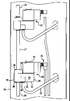
[0011] Figure 1 is an environnzental side view of two valve assemblies of the
present
invention mounted to ainounting plate of a larger process apparatus and
connected in series to a
source of pressurized air;
[0012] Figure 2A is a cross-sectional view of the embodiment of the valve
assembly
illustrated in Figure 1 having a side mounted solenoid actuator;
[0013] Figure 2B is a partial cross-sectional view of the embodiment of the
valve assembly
illustrated in Figure 2A with the actuator in the de-energized position such
that the valve is closed;
[0014] Figure 2C is a partial cross-sectional view of the embodiment of the
valve assembly
illustrated in Figure 2A and 2B with the actuator in the energized position
such that the valve is
open;
[0015] Figure 3A is a side view of the embodiment of the valve assembly
illustrated in
Figures 2A, 2B, and 2C showing the valve body in detail;
[00161 Figure 3B is an opposing side view of the embodiment of the valve
assembly
illustrated in Figures 3A;
[0017] Figure 4A is a side view of one embodiment of the valve asseinbly of
the present
invention showing the quick mount latching assembly in cross-section prior to
the insertion of the
valve into a mounting plate opening;
[0018] Figure 4B is a side view of the valve assembly illustrated in Figure 4A
showing the
quick mount latching assembly in cross-section as the latching assembly is
first inserted into the
mounting plate opening;
[0019] Figure 4C is a side view of the valve assembly illustrated in Figures
4A and 4B
showing the quick mount latching assembly in cross-section as the latching
assembly is completely
6
CA 02473486 2004-07-09
-- ~
inserted into the mounting plate opening and the latching assembly is
retaining the valve to the
mounting plate;
[0020] Figure 5A is a cross-sectional view of the another embodiment of a
valve assembly of
the present invention having a top mounted actuator with the actuator in the
de-energized position
such that the valve is closed;
[0021] Figure 5B is a cross-sectional view of the valve assembly illustrated
in Figure 5A
having a top mounted solenoid actuator with the actuator in the energized
position such that the
valve is open;
[0022] Figure 6A is a side view of the valve assembly illustrated in Figures
5A and 5B
having a top mounted solenoid actuator; and
[0023] Figure 6B is the opposing side view of the valve assembly illustrated
in Figure 6A.
DETAILED DESCRIPTION OF THE PREFERRED EMBODIMENT(S)
[0024] Referring now to the figures, where like numerals are used to designate
like structure
tliroughout the drawings, a pneumatic valve assembly of the present invention
is generally indicated
at 10 and 210. As shown in Figure 1, two valve assemblies 10 of the present
invention are
pneumatically interconnected in series with a source of pressurized air. Each
of the valve assemblies
includes a valve body 12 and an electromagnetic actuator assembly, such as a
solenoid, generally
indicated at 14 and rnounted to the valve body 12. The valve body 12 has a
thin rectangular shape
defining top and bottom surfaces 16, 18, respectively, a pair of opposed side
surfaces 20, 22
extending between the top and bottom surfaces 16 and 18 and end surfaces 24,
26. The actuator
assembly 14 is niounted to the side surface 20 of the valve body 12. The
actuator of the present
invention may be of any known type typically used in pneumatic valves such as
an electromagnetic
7
CA 02473486 2007-02-07
solenoid having a floating armature with lost-motion biasing as described in
prior art U.S. Patent
Nos. 4,438,418 or 3,538,954.. Thus,
those having ordinary skill in the art will appreciate from the description
that follows that the exact
form of the actuator, whether electromagnetic or otherwise, forms no part of
the present invention.
The actuator 14 is in electrical communication with a control device through a
wiring harness as
generally indicated at 15 in Figure 1.
100251 The valve body 12 is adapted to be mounted to an attachment, or
mounting plate 28.
It should be appreciated that the mounting plate 28 is in some manner affixed
to a processing device,
a conveyor system, or some other larger mechanism that requires the controlled
application of
pneumatic pressure as supplied by the valve assemblies of the present
iinvention. More specifically,
the placement of the mounting plate 28 and the general placement of the valve
assemblies 10 on the
mounting plate 28 is driven entirely by the overall design of the greater
device or system. Thus, the
two valve assemblies 10 as illustrated in Figure i are shown in close
proximity for the purpose of
discussion and may or may not be so closely located in operation.
[0026] Referring now to Figures 2A through 3B, the valve body 12 includes a
pressurized air
supply inlet port 30 in fluid communication with a source of pressurized air,
an outlet port 32
adapted to be in fluid communication with at least one active pneumatically
operated device, and a
pass-through passage 34 adapted to be in fluid communication with and provide
a pass-through of
the supply of pressurized air to the inlet port of a substantially similar
valve assembly 10 such that
the valves are mounted in series with regard to the supply of pressurized air.
More specifically, the
pass-through passage 34 is a bore that extends through the valve body 12 and
has a pass-through inlet
36 and a pass-through outlet 38. The pass-through inlet and outlet 36 and 38
each include a "quick
connect" fitting generally indicated at 40, which will be discussed in greater
detail below. The outlet
8
CA 02473486 2004-07-09
port 32 also has "quick connect" fitting generally indicated at 42 disposed in
the outlet opening 44.
The pneumatic connection of one valve assembly 10 to a second valve assearibly
10 can be seen in
Figure 1 where the valves are in fluid communication with each other through a
piece of pneumatic
conduit, or tubing 17. As shown in Figure 1, the source of pressurized air is
supplied through tubing
piece 19 to the pass-through inlet 36 of the first valve assembly 10. The
pressurized air then passes
through the pass-through passage 34 of the first valve 10 and out the pass-
through outlet 38 to the
pass-through inlet 36 of a second valve by way of pneumatic tubing 17.
F'urther, the source of
pressurized air continues on to another remote valve assembly 10 througll
tubing 21. Tlle controlled
output of pressurized air from the outlet 44 of valve assembly 10 is delivered
to the actively control
pneumatic device by way of tubing 23.
100271 A valve bore 46 extends axially through the valve body 12. In the
embodiment
illustrated here, the pneumatic valve assembly 10 is a two-way valve and also
includes an exhaust
port 48 in fluid communication with the valve bore 46. In the embodiment
illustrated in the figures,
the valve bore 46 extends completely through the valve body 12 to present a
pair of open ends 50,
52. A valve member, generally indicated at 54, is movably supported within the
valve bore 46
between predetermined positions to selectively direct a flow of pressurized
air from the inlet port 30
through the valve bore 46 to the outlet port 32. Concomitantly, the valve
member 54 also selectively
directs pressurized air to vent from the outlet port 32 to the exhaust port
48, as will be described in
greater detail below. An end retainer insert, generally indicated at 56 is
received in the open end 52
of the valve body 12, thereby retaining the valve member 54 within the valve
bore 46 as will be
described in greater detail below.
[00281 The valve member 54 further includes a valve element 58 disposed along
its length.
The valve element 58 is formed on the valve inember 54 and has valve sealing
surfaces 60 and 62
9
CA 02473486 2007-02-07
that are operable to selectively direct a flow of pressurized air from an
inlet port 30 through the valve
bore 36 to the outlet port 32 and from the outlet port 32 to the exhaust port
48, respectively. As
shown in Figures 2A through 2C, the valve member 54 further includes an
annular groove 64 that
receives an o-ring type seal 66, which slidingly engages the open end 50 of
the valve bore 46 to
prevent leakage of the pressurized air from the valve bore 46. The valve
member 54 also includes a
cup-shaped recess 68 that accepts and retains a biasing member 69.
[0029] In the preferred embodiment, the valve member 54 is an aluminum insert
that is over-
molded with a suitable resilient material such as rubber, or any known
elastomer, in the appropriate
place. More specifically, it should be appreciated by those having ordinary
skill in the art that the
material of the sealing surface may be made of any known composition that is
slightly yielding, yet
highly resilient, such as nitrile, which may be bonded, or over-molded to the
valve member 54.
[0030] As shown in Figures 2A and 2B, the valve seat 70 is disposed directly
in the valve
bore 46 itself, while valve seat 72 is disposed in the end retainer insert 52.
The end retainer insert 52
includes an annular groove 80, which receives an o-ring type seal 82 to
prevent leakage of the
pressurized air within the valve bore 46. The end retainer insert 52 has a
central bore 84 that
receives the valve member 54 and allows it to slidingly move within the valve
body 12. The end
retainer insert 52 is secured in the valve body 12 by the exhaust port
diffuser assembly, which is
generally indicated at 86. The diffuser assembly 86 includes a diffuser plate
88 and a retainer 90.
Exhaust openings 92 are formed in the retainer 90 so that as pressurized air
is allowed to enter the
exhaust port 48 it passes through the diffuser plate 88 and through the
exhaust openings 92 to the
atmosphere. The diffuser plate 88 is a membrane that allows air to pass but
prevents foreign objects
from entering the exhaust port 48. The retainer 90 of the diffuser assembly 86
is threadably inserted
in the valve body 12, so that the diffuser assembly 86 is in contact with and
thus secures the end
CA 02473486 2004-07-09
retainer insert 52 in the valve body 12. The diffuser assembly 86 is also in
contact with one end of
the biasing member 69. The biasing member 69 is disposed in the cup-shaped
recess 68, which is
fonned in one end of the valve member 54, such that the biasing member 69
provides a force
operative to move the valve meinber 54 away from the diffuser assembly 86 in
opposition to a force
generated by the actuator assembly 14. The biasing member 69 may be a coiled
spring or the like.
100311 In operation, the valve seats 70 and 72 cooperate with the valve
elements 60 and 62,
respectively, to seal the various passages in the valve body 12. The valve
seat 70 provides a sealing
contact with the valve sealing surface 60 of the valve elernent 54 when the
valve meniber 46 is in the
de-energized position (Figure 2A) thereby interrupting the flow of pressurized
air to the outlet port
32. While in this position, the valve sealing surface 62 is moved away from
valve seat 72, so that the
outlet port 32 is open to and in fluid communication with the exhaust port 48.
This allows any
pressurized air in the outlet to be vented to the atmosphere through the
exhaust port 48. Likewise,
the valve sealing surface 60 is moved away from valve seat 70 when the valve
member 46 is in an
energized position, thereby allowing the flow of pressurized air from the
inlet port 30 to the outlet
port 32. While in this position, the valve seat 72 provides a sealing contact
with the valve sealing
surface 62 of the valve elenlent 54 so that the outlet port 32 is closed off
from the exhaust port 48
and pressurized air from the inlet port 30 is delivered to the outlet port 32.
[00321 In the preferred embodiment, the actuator assembly 14 is mounted upon
the valve
body 12 so as to engage and thereby actuate the valve meinber 54. As shown for
illustration
purposes only, this may be accomplished by the use of an actuator pushpin 96
having a.n enlarged
head 98 that contacts the end of the valve member 54 opposite the biasing
member 69. bl this
maimer, the actuator assembly 14 is operable to move the valve member to the
right, as illustrated in
Figure 2A - 2C, thereby actuating the valve assembly 10. lt should be
appreciated by those having
11
CA 02473486 2004-07-09
ordinaiy skill in the art that the specific actuating means used to provide
motive force to the valve
member 54 lies beyond the scope of the present invention. Accordingly, it
should be further
appreciated that any number of different types of actuating elements, rather
than a push pin, may be
employed based on the actuating n7eans used. As previously mentioned, the
actuator assembly 14 is
used to selectively actuate the valve member 54 within the valve bore 46 in
the direction opposite to
the biasing force of the biasing member 69. In this manner, the actuator
assembly 14 drives the
valve member to the right, as shown in Figure 2C, and the biasing member 69
returns the valve
tnember 54 to its original position (to the left, in Figure 2B) when the
actuator assembly 14 is
deactivated.
(0033] In the preferred embodiment, the actuator asseinbly 14 is mounted to
the valve body
12 by the use of two threaded fasteners 100 (Figure 3B) that allow for the
rapid removal and
replacement of the actuator assembly 14 from the valve body 12 without having
to depressurize the
system. It should be appreciated that various other means of attaching the
actuating assembly 14 to
the valve body 12 are available that provide a like rapid removal and
replacement feature. As such,
any other known manner of like actuator attachment may be employed without
departing from the
scope of the invention.
[0034] The quick connect fittings 40 a.nd 42 are of a known type of "push-in
locking
connector" for pneumatic tubing having a main body 102, a locking collar 104,
a release sleeve 106,
and an o-ring seal 108. The valve body 12 includes fitting bores 110 and 112
that are each fornled to
receive the main body 102 of the fittings 40. Similarly, the valve body
includes a fitting bore 114 to
receive fitting 42, which is substautially similar but of slightly smaller
size. The main body 106 of
the fitting may be retained in the fitting bore by one of any various known
methods. For example,
the main body 106 of the fitting and the fitting bores 110, 112, and 114 may
be a close tolerance fit
12
CA 02473486 2007-12-03
in which the fittings 40, 42 ai-e pressed into the bores. Eacli of the main
bodies 110 of the ftttings 40
include an externally formed gi-oove 116 that retains an o-ring type seal 118
that seals the inain
bodies 106 to the bores 110, 112, and 114.
C00351 In each of the fittings 40, 42, the release sleeve has an inner
diameter 120 that is
approximately the satne size as the outer diaineter of the tubing that is to
be inserted and retained,
whicli provides physical support to the tubing. The locking collar 104 also
has an internal diameter
122 that is approximately the sanle size as the tubing that is to be inserted
and retained.
However, the locking collar 104 fut-thet- includes a plurality of engaging
tabs 124 that flexibly extend
inwardly fi-om its inner diameter 122. The engaging tabs 124 are also angled
away fi=otn the opening
of the release sleeve 106. In this manner, when a pneumatic tube is inserted
into the fitting 40 to
provide fluid communication, its end is pushed past the engaging tabs 124 of
the locking collar 104
and past the o-ring seal 108 to a stop flange 126. The o-ring seal 108
provides a sealing engagement
to the outside diatneter of the tube and the plul-ality of eilgaging tabs 124
of the locking collar 104
press inward against the outer diameter of the tube. The angle of the engaging
tabs 124 thus prevents
extraction of the tube fi=om the niain body 102 of the fitting 40. The release
sleevc 106 is slidingly
disposed within the rnain body 102 so that when it becomes necessary to i-
emove the tube from the
fitting 40, the releasc sleeve 106 is pressed inward relative to the main body
102 so that the forward
edge 128 of the release sleeve 106 forces the engaging tabs 124 away fi-om the
outer dianieter of the
tube. The tube is tlieta free to be extracted from the fitting 40, 42.
100361 As best shown in Figures 3A - 3B, the valve body 12 also includes a
latching
assembly 130 that is used to releasably mount the valve body 12 to the
mounting plate 28. The
latching assembly 130 extends away from the valve body 12 and has a first
flanged lip 132 extending
laterally outward from the valve body 12 and a second flanged lip 134 disposed
opposite to the first
13
CA 02473486 2004-07-09
flanged lip 132 on the latcliing assembly 130. The flanged lip 134 also
extends laterally outward
from the valve body 12. In the preferred emvodiment of the present invention,
the latching assembly
130 is an integrally formed portion of the valve body 12 that extends away and
is spaced apart from
the valve body 12. As best shown in Figure 4A, 4B, and 4C, the latching
assembly 130 is adapted to
engage and be operatively retained within an aperture 140 in the mounting
plate 28 without the use
of fasteners. The first flanged lip 132 defines a first mounting channel 136
that is adapted to accept
and retain one side, or upper portion 150 of the aperture 140. The second
flan,ged lip 134 defines a
second mounting channel 138 that is adapted to accept the opposite side, or
lower portion 152 of the
mounting plate aperture 140. In its operative mode, the flanged lips 132, 134
extend beyond the
edges of the mounting plate apertttre 140 to affix the valve body 12 to the
mounting plate without
fasteners. In the preferred en-tbodiment of the present invention, the
aperture 140 of the mounting
plate 28 is formed to have a generally square shape and the latching assembly
130 is formed so that it
will fit into the aperture as described in greater detail below.
[00371 More specifically, the latching assembly 130 further includes a biasing
bore 142
formed within the latching asseinbly 130. The biasing bore 142 has an open end
144 proxiinate to
the second flang.ed lip 134 and a closed end 146 proximate to the first
flanged lip 132. The biasing
bore 142 receives a biasing latch member 148. In the preferred embodiment of
the present invention,
the biasing latch membei= 148 is a coiled spring. One end of the biasing latch
member 148 is retained
at the closed end of the biasing bore 142 while allowing the opposite end of
the biasing latch
member 148 to extend beyond the second mounting channel 138 to the edge of the
second flanged
lip 134. Thus, when the valve assembly 12 is installed in the mounting plate
28, the biasing latch
member 148 is adapted to provide a biasing force between the edge of the
mounting plate aperture at
the second mounting channel 138 and the closed end of the biasing bore 146. In
this manner, the
14
CA 02473486 2007-12-03
biasing latch incmber 148 forces the first mounting channel 136 of the
latching assembly 130 upward
against the edge of the mounting plate apertuz-e 140 to retain the valve
assembly 12 without fasteners.
[00381 To attach the valve assenlbly 10 to the mounting plate 28, the second
mounting
channel 138 of the latclling asserrably 130 is directed toward the lower
portion of the mounting plate
aperture 140, as best shown in Figure 4A. As shown in Figure 4B, the second
inounting channel 138
is engaged upon the lower portion of the mounting plate apertui-e 140 and the
biasing latch nzeinber
148 is compressed until the fii-st flanged lip 132 will c1ea1- the upper poi-
tion of the mounting plate
apei-ture 140. Then, the valve assembly 10 is rotated back about the second
mounting channel 138 so
that the first flanged lip 132 passes through the mounting plate aperture 140.
Finally, the valve
assembly 10 is released so that the biasing latch nienlber 148 for-ces the
valve asselnbly 10 upward to
engage the fii=st nlounting channel 136 to the ilpper portion of the mounting
plate aperture 140.
Thus, the valve asseznbly 10 is retained in the nlounting plate aperture 140
without the use of
fasteners, as shown in Figure 4C. Wliile the latching assembly 130 and the
aperture 140 are
illustrated hei-e having a generally square shape, it should be appreciated
that the mounting plate
aperture 140 and the latching assembly 130 may be forined in any of a variety
of different sllapes as
long as they al-e cooperatively shaped.
[0039] Another non-Iimiting embodiment of the valve assembly of the present
invention is
generally indicated at 210 in Figures 5A and 5B, where like nunlerals
indicating like structure with
respect to the valve assenibly 10 have been increznented by 200. In this
enlbodiment, the valve
assembly 210 employs atop nlounted actuator. More specifically, the valve
assenlbly 210 includes a
valve body 212 and an electromagnetic actuator asscmbly, sueh as a solenoid,
generally indicated at
214 and mounted to the valve body 212. The valve body 212 lias a thin
rectangular shape defining
top and bottoni sEUfaces 216, 218, respectively, a pair of opposed side
surfaces 220, 222 extending
CA 02473486 2004-07-09
between the top and bottom surfaces 216 and 218 and end surfaces 224, 226. The
actuator assembly
214 is mounted to the top surface 216 of the valve body 212.
[00401 The valve body 212 includes a pressurized air supply inlet port 230 in
fluid
communication with a source of pressurized air, an outlet port 232 adapted to
be in fluid
communication with at least one active pneumatically operated device, and a
pass-through passage
234 adapted to be in fluid colrnnunication with and provide a pass-through of
the supply of
pressurized air to the inlet port of a substantially similar valve assembly
210 such that the valves are
mounted in series with regard to the supply of pressurized air. More
specifically, the pass-througla
passage 234 is a bore that extends through the valve body 212 and has a pass-
through inlet 236 and a
pass-through outlet 238. The pass-through inlet and outlet 236 and 238 each
include a "quick
coiulect" fitting generally indicated at 240. The outlet port 232 also has
"quick connect" fitting
generally indicated at 242 disposed in the outlet opening 244.
[00411 As best shown in Figures 6A and 6B, a valve bore 246 extends vertically
through the
valve body 212. In the enlbodiment illustrated here, the pneumatic valve
assembly 210 is a three-
way valve and also includes an exhaust port 248 in fluid communication with
the valve bore 246.
The valve bore 246 extends partially through the valve body 212 to present one
open end 250 and a
closed end 252. A valve member, generally indicated at 254, is movably
supported within the valve
bore 246 between predetermined positions to selectively direct a flow of
pressurized air from the
inlet port 230 through the valve bore 246 to the outlet port 232.
Concomitantly, the valve member
254 also selectively directs pressurized air to vent from the outlet port 232
to the exhaust port 248.
[0042] The valve member 254 further includes a valve element 258 disposed
along its length.
The valve element 258 is fonued on the valve member 254 and has valve sealing
surfaces 260 and
262 that are operable to selectively direct a flow of pressurized air from an
inlet port 230 through the
16
CA 02473486 2004-07-09
valve bore 236 to the outlet port 232 and from the outlet port 232 to the
exhaust port 248,
respectively. As shown in the figures, the valve member 254 further includes
an annular groove 264
tliat receives an o-ring type seal 266, which slidingly engages the open end
250 of the valve bore 246
to prevent leakage of the pressurized air from the valve bore 246. The valve
member 254 also
includes a cup-shaped recess 268 that accepts and retains a biasing member
269.
[0043] In the preferred einbodiment, the valve member 254 is an aluminum
insert that is
over-molded with a suitable resilient material such as rubber, or any known
elastomer, in the
appropriate place. More specifically, it should be appreciated by those having
ordinary skill in the
art that the material of the valve element 258 having sealing surfaces 260 and
262 may be made of
any known composition that is slightly yielding, yet highly resilient, such as
nitrile, which may be
over-molded to the valve member 254.
[0044J A biasing member 269 is disposed in the cup-shaped recess 268 fon-ned
in one end of
the valve menlber 254 such that the biasing member 269 provides a force
operative to move the
valve member away from the closed end 251 of the valve bore 246 in opposition
to a force generated
by the actuator assembly 214. The biasing member 269 may be a coiled spring or
the like. In the
prefet-red embodiment, the actuator assembly 214 is mounted upon the valve
body 212 so as to
engage and thereby actuate the valve member 254. As shown for illustration
purposes only, this may
be accomplished by the use of an actuator pushpin 296 having an enlarged head
298 that contacts the
end of the valve member 254 opposite the biasing member 269. In this manner,
the actuator
assembly 214 is operable to move the valve member 254 down as seen in Figure
6B, thereby
actuating the valve assembly 210. It shotzld be appreciated by those having
ordinary skill in the art
that the specific actuating means used to provide motive force to the valve
member 254 lies beyond
the scope of the present invention. Accordingly, it should be further
appreciated that any number of
17
CA 02473486 2004-07-09
different types of actuating elements, rather than a push pin, may be employed
based on the actuating
means used. As previously mentioned, the actuator assembly 214, as previously
mentioned, is used
to selectively actuate the valve member 254 within the valve bore 246 in the
direction opposite to the
biasing force of the biasing meinber 269. In this manner, the actuator
assembly 214 drives the valve
member down, as shown in Figure 6B, and the biasing member 269 returns the
valve member 254 to
its original position (upward, in Figure 6A) when the actuator assembly 214 is
deactivated.
[00451 In operation, the valve seats 270 and 272 cooperate with the valve
sealing surfaces
260 and 262, respectively, to seal the various passages in the valve body 212.
The valve seat 270
provides a sealing contact with the valve sealing surface 260 of the valve
element 258 when the
valve member 254 is in the de-energized position (Figure 5A) thereby
interrupting the flow of
pressurized air to the outlet port 232. While in this position, the valve
sealing surface 262 is moved
away from valve seat 272 so that the outlet port 232 is open and in fluid
communication with the
exhaust port 248. This allows any pressurized air in the outlet to be vented
to the atmosphere through
the exhaust port 248. Likewise, the valve sealing surface 260 is moved away
from valve seat 270
when the valve member 254 is in an energized position, thereby allowing the
flow ofpressurized air
from the inlet port 230 to the outlet poi-t 232. While in this position, the
valve seat 272 provides a
sealing contact with the valve sealing surface 262 of the valve element 258 so
that the outlet port 232
is closed off fronz the exhaust port 248 and pressurized air from the inlet
port 230 is delivered to the
outlet po1-t 232. The exhaust port 248 includes a diffuser assembly 286 that
is retained in the valve
body 212 so that as pressurized air is allowed to enter the exhaust port 248
it passes through the
diffuser assembly 286 prior to venting to the atmosphere. The diffuser
assembly 286 is a membrane
that allows air to pass but prevents foreign objects from entering the exhaust
port 248.
18
CA 02473486 2004-07-09
[0046] In the preferred embodiment, the actuator asseinbly 214 is mounted to
the top surface
216 of the valve body 212 which allows for the rapid removal and replacement
of the actuator
assembly 214 from the valve body 212 without having to depressurize the
system. It should be
appreciated that various other means of attaching the actuating assembly 214
to the valve body 212
are available that provide a like rapid removal and replacement feature. As
such, any other known
manner of like actuator attacllment may be employed without departing from the
scope of the
invention.
[0047] The quick connect fittings 240 and 242 are of a known type of "push-in
locking
connector" for pneumatic tubing as previously described above. The valve body
212 includes fitting
bores 310 and 312 that are each formed to receive the fittings 240. Similarly,
the valve body
includes a fitting bore 314 to receive fitting 242, which is substantially
similar but of slightly smaller
size. The quick connect fittings 240, 242 are the same as fitting 40, 42 and
so the description of the
subcomponents of these elements will not be repeated here.
[0048] As best shown in Figures 5A - 5B, the valve body 212 also includes a
latching
assembly 330 that is used to releasably mount the valve body 212 to the
mounting plate 28 (Figure
1). The latching assembly 330 extends away from the valve body 212 and has a
first flanged lip 332
extending laterally outward from the valve body 212 and a second flanged lip
334 disposed opposite
to the first flanged lip 332 on the latching assembly 330. The flanged lip 334
also extends laterally
outward from the valve body 212. As in the above described einbodiment, the
latching assembly 330
here is an integrally formed portion of the valve body 212 that extends away
and is spaced apart from
the valve body 212. The latching assembly 330 has a first and second flanged
lip 332 and 334,
which form first and second mounting channels 336 and 338. Likewise, a biasing
bore 342 retains a
biasing latch member 348. The latching assembly 330 is adapted to engage and
be retained in
19
CA 02473486 2004-07-09
mounting plate 28 in a manner identical to that in which valve assembly 10 is
operatively retained
within an aperture 140 in the mounting plate 28 and without the use of
fasteners, as shown in Figures
4A, 413, and 4C.
[0049] The above-described embodiments of the present invention overcome the
drawbacks
and disadvantages of conventional valve assemblies that require costly amounts
of downtime to
remove and replace. Specifically, the present invention avoids the current
methods of affixing valve
assemblies to a mounting plate or attachment surface using a variety of
fasteners. Furthermore, the
pressurized connections at the inlet, outlet, and pass-through of the present
invention do away with
the requirement of the use of known, conventional types of threaded fasteners
that do not lend themselves to quick mounting or replacement. Therefore, the
present invention provides a solenoid
actuated pneumatic valve assembly that overcomes these deficiencies by
providing the ability to be
rapidly and readily removed and replaced.
[0050] The invention has been described in an illustrative manner. It is to be
understood that
the terininology, which has been used, is intended to be in the nature of
words of description rather
than of limitation. Many modifications and variations of the invention are
possible in light of the
above teachings. Tllerefore, within the scope of the appended claims, the
invention may be practiced
other than as specifically described.