Note: Descriptions are shown in the official language in which they were submitted.
CA 02473567 2004-07-15
WO 03/033065 PCT/IB02/04249
A DISPOSABLE DEVICE FOR TRANSFERRING AND/OR CIRCULATING AN ACTIVE LIQUID INTO
AND/OR
INSIDE AN INTRACORPOREAL CAVITY
This nonprovisional application claims the benefit of U.S. Provisional
Applications No. 601329,293, filed October 16, 2001, No. 60/329,332, filed
October
16, 2001, No. 60/331,127, filed November 8, 2001, No. 60/350,041, filed
January 23,
2001, and No. 601406,638, filed August 29, 2002, the entire contents of each
of which
is hereby incorporated by reference.
FIELD OF THE INVENTION
The present invention concerns the transfer and/or circulation of an active
liquid into/inside an intracorporeal cavity of the human body or of an animal,
especially
in contact with mucous membrane of said cavity.
BACKGROUND AND DEFINITIONS
"Intracorporeal cavity" signifies any cavity of the body, particularly an
elongate one, which can be accessed from the outside for different purposes,
in
particular for clinical, therapeutic, prophylactic or diagnostic purposes, but
also for
cosmetic or personal hygiene purposes. One example of such a cavity is the
vagina of a
woman, which extends from the vulva to the neck of the uterus or cervix, and
into/inside which it is desired to transfer and/or circulate an active liquid
in contact
with the mucous membrane and/or the tissues of said cavity.
"Active liquid" signifies any liquid or fluid for local treatment or delivery,
by a topical route, and/or for systemic treatment or delivery, comprising in a
general
manner a liquid or fluid phase in which an active agent is dispersed, for
example in
solution or suspension.
This active agent may be at least one compound or substance selected
from the group consisting of wetting agents, solubilizing and liquefying
agents, in
particular of a bodily liquid or fluid present in the intracorporeal cavity,
therapeutic
agents against infectious and non infectious diseases, prophylactic agents,
diagnostic
agents, immunotherapeutic agents, cosmetic or personal hygiene agents,
antiseptic
agents, bactericidal agents, fungicidal agents, and spermicidal agents (in the
case of the
vaginal cavity of the woman, for example), local treatment agents, systemic
treatments
agents, trophic agents and lubricant agents.
The liquid or fluid phase (depending on its viscosity) of said active liquid
may comprise at least any liquid or natural fluid (such as a body fluid)
originally
present or naturally generated or secreted in said intracorporeal cavity, if
any.
CA 02473567 2004-07-15
WO 03/033065 PCT/IB02/04249
2
In accordance with the embodiment shown in Figure 4 of International
Patent Application Publication No. WO 00/45887, a disposable device has been
described and proposed for transferring and/or circulating an active liquid
into/inside an
intracorporeal cavity, said device being elongate along a reference axis and
having an
intrinsic axial or longitudinal consistency which is soft but stiff or strong
enough to
allow it to be introduced into said cavity by being pushed in axially, without
altering
the structure of the device, particularly without dissociating its various
components
and/or rupturing a capsule, if any.
This device comprises:
- a distal capsule, generally in the shape of a pear, having a relatively
thick
wall made of a liquefiable substrate which is relatively solid at ambient
temperature,
that is to say outside the intracorporeal cavity, and which becomes relatively
liquid
inside said intracorporeal cavity; in this way, the substrate at least
partially liquefies
inside said intracorporeal cavity and the wall of said capsule disrupts; this
capsule
comprises or incorporates a liquid charge, enclosed by the aforementioned wall
in a
leak tight manner relative to the outside of the capsule; an active agent as
defined above
is distributed in the substrate and/or the liquid charge;
- a proximal expandable tampon, generally with the shape of an egg, made
of an absorbent material, joined to the aforementioned capsule and designed to
collect
and absorb said active liquid dispensed in the intracorporeal cavity and, in
time, to
expand and bear in a leak-tight manner against the mucous membrane of the
intracorporeal cavity; this tampon is obtained from a porous material such as
an open-
pore foam of a suitable synthetic resin, or alternatively cellulose wadding;
- a covering for temporary protection enveloping the entire capsule and the
tampon which are joined to each other, covering the proximal end of the tampon
and
the distal end of the capsule.
Thus, according to this publication and also to the present invention as
hereunder defined and described:
- the liquid or fluid phase of said active liquid comprises, in addition to
any natural liquid or fluid originally and possibly present in the
intracorporeal cavity, at
least part of the liquid charge enclosed by the capsule of the device, and
possibly at
CA 02473567 2004-07-15
WO 03/033065 PCT/IB02/04249
3
least part of the liquefied form of any liquefiable substrate making part of
the device,
for instance of which the walls of the capsule are made ;
- any liquefiable substrate means any matter, substance, compound or
composition, originally or naturally occurring in solid form, for instance at
ambient
temperature and/or outside said intracorporeal cavity, and capable of any
transformation into a liquid or fluid form by any phenomenon, such as melting
and/or
dissolution, at least in part, etc., under one or more conditions prevailing
in said
intracorporeal cavity, such as the body temperature, the presence of a body
fluid or
liquid, a specific pH condition, etc.; examples of such liquefiable substrates
include
sucrose, gelatine and alginates.
Where the active agent is hydrophilic, the liquid phase is preferably
hydrophilic, or where the active agent is hydrophobic or lipophilic the liquid
phase is
preferably hydrophobic or lipophilic.
For example, the active liquid may be a solution, a suspension, an
emulsion, a colloid or other fluid.
SUMMARY OF THE INVENTION
One object of this invention is a device as defined above, which can be
maintained in position in the intracorporeal cavity, once and as soon as said
device is
inserted into said cavity.
A further object of this invention is a device allowing the active liquid to
efficiently spread over the mucous membrane of the intracorporeal cavity,
before being
absorbed by the tampon of the same device.
With a specific reference to the vagina, a further object of this invention is
a device allowing a specific treatment of the cervix.
A further object of the present invention is to provide a disposable device
allowing better availability of the active agent.
Another object of the present invention is to provide a non-traumatic
device with ease of use for the end user or patient.
Another object of the present invention is to provide a device which is
relatively simple to manufacture and mass-produce.
Individual ones and combinations of two or more and in embodiments all
of these objects are generally served by a disposable device for transferring
and/or
CA 02473567 2004-07-15
WO 03/033065 PCT/IB02/04249
4
circulating an active liquid into and/or inside an intracorporeal cavity, said
device being
elongate along a reference axis, said device having an intrinsic axial
consistency which
is sufficient to allow said device to be introduced into said cavity by being
pushed in
axially, said device comprising:
S - an expandable tampon made of at least one absorbent material, having
a proximal portion and a distal portion, designed to collect and absorb said
active liquid
dispensed in the intracorporeal cavity and to expand and bear in a leak-tight
manner
against mucous membrane of the intracorporeal cavity;
- a source of liquid phase comprising a capsule at least the proximal part
of which is at least partially surrounded by said expandable tampon;
- a covering for temporary protection at least partially covering the distal
portion of said capsule, and extending longitudinally to an intermediate level
of the
tampon in such a way as to form in said tampon a proximal plug not covered by
said
covering, which is at least radially expandable independently from the
remaining part
of said tampon.
i. e.
The present invention has two especially preferred types of embodiments,
- a first embodiment, wherein said capsule has a wall made of a liquefiable
substrate which is relatively solid at ambient temperature, outside the
intracorporeal
cavity, and which becomes relatively liquid inside said intracorporeal cavity,
so that
said substrate at least partially liquefies inside said intracorporeal cavity
and said wall
disrupts, and wherein said capsule has a liquid charge, enclosed by said wall
in a leak-
tight manner relative to the outside of said capsule, an active agent being
distributed in
a least one of said substrate and said liquid charge.
- a second embodiment, wherein said capsule comprises a plastic envelope
containing a liquid charge of said liquid phase enclosed by said envelope in a
leak-tight
manner relative to the outside of said capsule, an active agent being
distributed in said
liquid charge.
Other particular or specific objects of this invention are met by
embodiments of a device as described herein, and comprising at least one of
the
following limitations, considered independently from one another
CA 02473567 2004-07-15
WO 03/033065 PCT/IB02/04249
(a) the expandable tampon is designed to expand radially (inward and/or
outward), and possibly longitudinally or axially;
(b) the distal portion of the tampon is divided in at least two parts, or
tongues, that are independently and possibly in a differentiated manner,
axially
S expandable;
(c) there is provided an absorption barrier that reduces absorption of said
active liquid dispensed in the intracorporeal cavity by at least a portion of
the tampon;
preferably this absorption barrier is a coating of a repelling substance, not
miscible with
said active liquid, coating at least said portion of the tampon, and said
repelling
substance is hydrophobic or lipophilic where said active liquid is
hydrophilic, or
hydrophilic where said active liquid is hydrophobic or lipophilic;
(d) the tampon comprises at least one transverse capillary flow isolating
section;
(e) the tampon has an assembled composition made of at least a distal
section comprising tongues, a proximal section comprising the proximal plug,
and an
intermediate section between said distal and proximal sections, enclosed in a
ring of a
liquefiable substrate.
According to the present invention, there is also described a method of
transferring and/or circulating an active liquid into and/or inside an
intracorporeal
cavity, comprising inserting a device as described herein into and/or in
contact with the
mucous membrane of the intracorporeal cavity, and allowing a liquid phase to
be
released in said cavity.
The present invention also concerns an apparatus for making a device as
previously defined, comprising:
- means for radially compressing at least a first portion of an expandable
tampon,
- means for axially compressing at least a second portion of said
expandable tampon,
- means for providing said expandable tampon with a source of liquid.
BRIEF DESCRIPTION OF THE DRAWINGS
The present invention is now described with reference to the attached
drawings in which:
CA 02473567 2004-07-15
WO 03/033065 PCT/IB02/04249
6
- Figure 1 shows, in diagrammatic form, a cross section through a device
according to a first embodiment of the invention;
- Figure 2 shows, in diagrammatic form and in cross section, the device
shown in Figure 1, in position in a vaginal cavity;
- Figures 3 to 6 illustrate the different phases of functioning of a device
according to the first embodiment of invention, once it has been placed in an
intracorporeal cavity;
- Figures 7 and 8 and Figures 9 and 10 shows in part, respectively, a
device according to a second embodiment of the invention;
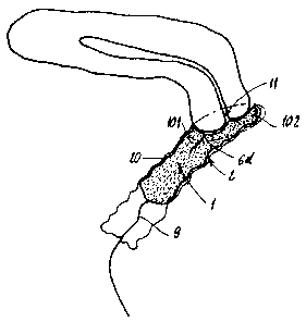
- Figure 11 shows, in diagrammatic form and in cross section, a device as
is shown in Figures 7 and 8 or 9 and 10, in position in a vaginal cavity;
- Figure 12 shows, in diagrammatic form and in cross section, a device
according to a third embodiment of the present invention;
- Figures 13 and 14 show alternative embodiments of devices similar to
those shown in Figures 7-10;
- Figure 15 shows the cross-section of an expandable tampon formed
according to the invention;
- Figure 1G shows an exemplary apparatus for forming an expandable
tampon of the invention;
- Figure 17 shows an alternative compression device that may be used in
forming an expandable tampon of the invention;
- Figure 18, in a manner similar to Figure 9 but in axial cross section,
shows the mode of impregnation of a tampon belonging to a device according to
the
present invention, before its positioning in the intracorporeal cavity;
- Figure 19, in a manner similar to Figure 18, shows the tampon in the
state when impregnated by the active liquid;
- Figure 20 shows a variant of the first embodiment according to the
present invention;
- Figure 21 is a side perspective view of a tampon showing a string
arrangement of the invention;
- Figure 22 is a cross-sectional view of the tampon of Figure 21;
CA 02473567 2004-07-15
WO 03/033065 PCT/IB02/04249
7
- Figure 23 is a cross-sectional and split view, in diagrammatic form, but
without any capsule, of a further embodiment of an invention device;
- Figure 24 represents, similarly to Figure 23, the device shown in the
same figure, but in its expanded configuration.
- Figure 25 represents in a schematic and comparative manner two
different embodiments of a device according to the invention, in its expanded
configuration within a female vagina; on the left part, a device according to
Figure 1 is
shown, whereas on the right part a device according to Figure 18 is shown.
DETAILED DESCRIPTION OF EXEMPLARY EMBODIMENTS
A disposable device 1 according to the invention generally permits the
transfer and/or circulation of an active liquid into/inside an intracorporeal
cavity 2, for
example a vaginal cavity (see Figures 2 and 11).
This device, elongate on a reference axis 15, has an intrinsic axial or
longitudinal consistency which is sufficient to allow its introduction into
the
aforementioned cavity by being pushed in axially.
The device of Figure 1 comprises:
- a source 21 of liquid phase comprising a distal capsule 3 having a
relatively thick wall 4, the latter being made of a liquefiable substrate
which is
relatively solid at ambient temperature, that is to say outside the
intracorporeal cavity,
and which becomes relatively liquid inside this same cavity, that is to say at
the
temperature of the human or animal body;
- a proximal expandable tampon 6 joined in an appropriate manner to the
capsule 3 and designed to collect and absorb active liquid dispensed in the
intracorporeal cavity and to expand and bear in a leak-tight manner against
the mucous
membrane 20 of the intracorporeal cavity 2;
- a covering 7 for temporary protection enveloping the capsule 3 and the
tampon 6 which are joined to each other, at least partially covering the
distal end of the
capsule 3;
- a withdrawal string 9 used for extracting the device 1 and inserted in a
loop shape in the tampon 6.
CA 02473567 2004-07-15
WO 03/033065 PCT/IB02/04249
8
The tampon 6 and the capsule 3 are preferably tailored to one another so
that they fit together by simple axial pushing of the capsule toward the
tampon, or vice
versa.
By virtue of the choice of substrate used for the wall 4 constituting the
S capsule 3, for example alginate, this at least partially liquefies in the
intracorporeal
cavity, and the wall 4 disrupts, leaving a passage to the liquid charge 5
originally
enclosed by said wall in a leak-tight manner relative to the outside of the
capsule 3.
Upon or after liquefying, the substrate may or may not form a further part,
in addition to the liquid charge, of the liquid phase for sustaining or making
the active
liquid transferred and/or circulated into andlor inside the intracorporeal
cavity 2.
At least an active agent as defined above is discretely distributed, e.g.
dissolved andlor suspended in the liquid charge 5. Alternatively, this active
agent can
be distributed in the liquefiable substrate of the wall of the capsule 3.
The capsule 3 encloses a liquid charge 5 in a leak-tight manner relative to
the outside of the capsule 3, and comprises a wall 4 forming a head 3a and
also an axial
tail3b of smaller transverse internal section than the head 3a.
Correspondingly, the
tampon 6 comprises an axial hole 6a for receiving the tail 3b of the capsule
3. As is
shown in Figure l, the head 3a has a convex proximal part 3c and,
correspondingly, the
axial hole 6a of the tampon 3 opens out onto a widened distal part 6b for
receiving the
head 3 a.
In the same way, and preferentially, the covering 7 for temporary
protection is made of a substrate which is relatively solid at ambient
temperature, that is
to say outside the intracorporeal cavity 2, and which becomes relatively
liquid inside
this intracorporeal cavity, so that this covering 7 is able to split open by
melting and/or
dissolution once the device 1 is placed in the intracorporeal cavity 2.
The covering 7 for temporary protection extends longitudinally or axially
to an intermediate but nonetheless proximal level of the tampon 6, in such a
way as to
form a proximal protective plug 8 not covered by the protective covering 7.
The substrate of the wall 4 of the capsule 3 and/or the substrate of the
covering 7 for temporary protection is preferably made of an alginate, or
sodium
alginate, alternatively called sodium polymannuronate. Such a compound in the
form of
a solid gel is able to become liquid upon contact with aqueous phase in which
it
CA 02473567 2004-07-15
WO 03/033065 PCT/IB02/04249
9
dissolves, e.g. a liquid or fluid, such as a body fluid, which may be present
in the
intracorporeal cavity 2.
In addition this substrate is biocompatible in the sense that if it contacts
the mucous membrane 20 of the intracorporeal cavity 2 it does not induce any
significant toxicity and/or inflammatory reaction.
The tampon 6 is designed to expand radially and possibly longitudinally;
in the radial dimension, in view of the axial hole 6a, it is designed to
expand inward
and/or outward. This tampon is made of one or more different materials or
parts, at
least one of which has an absorbing capacity; such an absorbing material is
for example
an open-pore foam of a plastic resin, for example polyurethane, or a fibrous
material of
cellulose such as a cellulose viscose sponge. The tampon G can be made by
molding,
shaping or extruding fibers, filaments, for instance natural fibers.
The expandable tampon 6 is preferably arranged in a compressed manner,
e.g., radially and/or axially compressed at least in areas of the tampon,
inside the
temporary protection covering 7.
As represented by Figure l, the expandable tampon 6 is a sleeve molded
or shaped from one absorbent material, for instance a cellulose viscose
sponge. The
tampon has a proximal portion 6c and a distal portion 6d that may or may not
extend as
far distally as shown in Figure 1. For example, it may extend only to the
convex
proximal part 3c of the head 3a of the capsule 3. Its overall absorbing
capacity is
designed, in terms of volume and/or predetermined and prior compression, so as
to
collect and absorb at least part and optionally the totality of the active
liquid dispensed
in the intracorporeal cavity following the action, or working of the device 1.
The
tampon 6 surrounds at least the proximal part, comprising the axial tail 3b of
the
capsule 3, leaving the distal part, portion or end of the same capsule
directly in contact
with the covering 7.
As described above, the protective covering 7 shown in Figure 1 frees a
proximal part of the tampon 6, which forms the plug 8 capable of at least a
radial
outward expansion independently from the remaining part of the tampon 6. More
generally, the tampon 6 has a proximal half and a distal half, and the
covering covers
said distal half and a portion but not all of said proximal half of said
tampon, leaving an
uncovered proximal part of said proximal half forming the proximal plug 8.
CA 02473567 2004-07-15
WO 03/033065 PCT/IB02/04249
By virtue of this construction, the proximal plug 8 belonging to the
tampon 6 is able to collect any liquid or fluid present in the intracorporeal
cavity 2
and/or a first part of the active liquid running downward along the device 1,
between
the covering 7 and the mucous membrane 20 of the intracorporeal cavity. On
account
5 of this collection, the plug 8, made of porous material as described above,
expands
radially outward and thus blocks the entire device, at its lower or proximal
part, in
position in the intracorporeal cavity 2, while the substrate of the covering 7
andlor the
wall 4 liquefies.
The withdrawal string 9 is attached to the proximal part or end of the
10 device 1, e.g. to the capsule 3 and/or the tampon G. As shown by Figure 1,
the
withdrawal string 9 is attached to the proximal portion la of the device, e.g.
in a
proximal portion of the tampon G or capsule 3. The withdrawal string 9 is a
loop, with
or without a knot, freely movable through the capsule 3 and/or the tampon G.
As shown
by Figure 1, the proximal portion Gc of the tampon 6 comprises a through hole
24
designed for the free passage of at least one, if not two or more strands, 9a,
9b of the
withdrawal string 9.
After insertion of the device 1 described with reference to Figure 1, and
once positioned in the intracorporeal cavity 2 as shown in Figure 2, the
different phases
of functioning of a device according to the invention are shown in Figures 3
to G
respectively.
The covering 7, if made of a low friction coating, makes it possible to
limit or eliminate contact between the mucous membrane 20 of the body cavity 2
and
the absorbent material when the tampon 6 is in the dry state at the time of
insertion of
the device 1; such contact could not only give rise to a not significant
amount of
friction but may also be a source of discomfort or pain to the user. On the
other hand,
by virtue of the configuration shown, almost the whole of the device, covered
with the
relatively slippery covering 7, slides in contact with the mucous membrane of
the body
cavity as the device is being inserted.
According to Figures 3-4, given the moisture (liquid or fluid) present in
the intracorporeal cavity 2, a relatively small initial quantity of liquid
phase (bodily
liquid or fluid present in the cavity 2 and/or starting liquid form of the
substrate of the
covering 7 and/or the wall 4) flows from the distal end of the device 1,
between the
CA 02473567 2004-07-15
WO 03/033065 PCT/IB02/04249
11
covering 7 and the mucous membrane 20 of the cavity 2, downward and along said
covering 7. This start of liquid phase is collected and absorbed in the plug
~, which
causes its radial expansion outward toward the mucous membrane 20 of the
cavity 2.
From the time of this expansion, the device 1 is held in position in the
cavity 2, while at
the same time sealing off the latter beyond the proximal end la of the device
1, with
respect to the aforementioned liquid phase.
As shown in Figures 4-5, given the radial centripetal pressure opposed by
the intracorporeal cavity 2, the tampon 6 is itself compressed. The distal
part of the
covering 7 and/or the distal part of the wall 4 of the capsule 3 liquefies,
beginning to
release the liquid charge 5 present in the capsule 3. The active liquid thus
formed then
flows from the capsule 3 onwards, ahead of the distal end lb of the device 1,
inside the
intracorporeal cavity 2, and toward the proximal end la of the device 1,
between the
covering 7 and the mucous membrane 20 of the cavity 2. This flow is promoted
by the
expansion and compression of the tampon 6, and pressurization of the inside of
the
capsule 3, in particular through its tail 3b.
As shown in Figure G, the active liquid phase arriving in the plug 8 allows
the expansion of the latter to continue, said expansion having an effect
within the
tampon G, pressurizing the liquid charge 5 in the capsule 3. The flow of the
active
liquid continues between the device 1 and the mucous membrane 20 of the
intracorporeal cavity 2, as described above.
Finally, as shown in Figure 6, the covering 7 splits open completely,
tearing if need be under the effect of the radial centrifugal pressure of the
tampon 6.
The latter fully expands radially, expelling practically all of the liquid
charge 5
originally present in the capsule 4, the latter having virtually disappeared.
Thus, a device 1 according to the present invention brings with it an
efficient method of transferring and/or circulating an active liquid into
and/or inside an
intracorporeal cavity 2, by the simple insertion of the device into and/or in
contact with
the mucous membrane 20 of the cavity 2, which automatically initiates the
liquid phase
to be released from the source 21 in the cavity 2.
As an example, a device l, as previously described, can be left in said
intracorporeal cavity 2 for less than one hour to several days, and preferably
for several
hours such as three to five hours, and then removed from said cavity.
CA 02473567 2004-07-15
WO 03/033065 PCT/IB02/04249
12
The embodiments shown in Figures 7 to 10 differ from the embodiment
with reference to Figure 1 in that the distal and peripheral portion 6d of the
tampon 6
has, around its axial hole 6a, at least two longitudinal or axial slits 22,
each passing
through said peripheral part, and forming between them at least two parts or
tongues 10
designed to expand, in particular axially or longitudinally, independently of
one
another, and possibly in a differentiated manner from one another.
According to Figures 7 and 8, there are two diametrically opposite
longitudinal slits 22 forming between them two opposite tongues or parts 10.
According to Figures 9 and 10, there are four cross slits 22 forming between
them four
tongues or parts 10. Other numbers of slits and tongues, e.g., 3, 5, 6 or
more, could also
be formed in the device.
As is shown more particularly in Figure 11, the arrangement previously
described with reference to Figures 7 to 10 makes it possible to arrange a
device
according to the invention in the vaginal cavity 2, until it bears against the
cervix 11.
One or more tongues 10, specifically referred to 101, then remain in
longitudinal or
axial abutment against the cervix 11, while one or more other tongues,
specifically
referred to 102, can continue to expand longitudinally until they seal the
cervix, as is
shown in Figure 11.
As shown by Figure 25, a device according to Figure 2 can be said normal,
whereas a device according to Figure 11 can be said anatomical, in that in its
expanded
configuration it fits in addition with the anatomy of the cervix.
Thus, according to Figure 11, at least one tongue 101, 102 expands
longitudinally or axially to seal and/or abut the cervix 11.
The number, shape, length and expandability of the tongues 10, 101, 102
shown by Figures 7 to 11 can be selected and controlled in accordance with
aspects of
the invention. For example, in certain embodiments of the invention, it is
preferred that
the cross-sectional area of the tongues 10 is less than that of the remainder
of the body
of the tampon 6. The location of the tongues 10 can be symmetrical, for
example as
shown Figures 7 to 10, or offset. The ends of the tongues 10 can be
differently shaped,
for example perpendicular to the expandable member axis, or at one or more
angles to
that axis or curved or the like.
CA 02473567 2004-07-15
WO 03/033065 PCT/IB02/04249
13
According to Figure 13, the tongues 10 are defined by shorter slits 20 than
in Figure 9, and in which the top of tongue l0a is sloped rather than
perpendicular with
respect to the axis of the device. Preferred tongue lengths include but are
not limited to
about 0.5 to about 2. S, such as about 1 to about 2 cm.
A device according to the embodiments respectively shown by Figures 7-
8, 9-10 and 11 can be made or manufactured in various ways. In particular, the
expandability features of the tampon G, including the tongues 10, 101 and 102
can be
achieved in various ways.
In preferred embodiments of this invention, the body 6f of the expandable
tampon 6 is first radially compressed, following which the area of tongues 10
is axially
compressed. However, the opposite order or simultaneous compression are also
possible. In an exemplary embodiment, a polygonal or circular cross-section
body 6f of
the material of expandable tampon 6 (see 6f in Figure 15) is compressed in a
die or
other compression member to achieve a desired diameter. Before, during or
preferably
after, such compression, a center core member 35 can be inserted into an end
of the
expandable tampon 6 to form the axial hole 6a. This can be achieved with or
without
previously forming a primary hole in the location of hole 6a. The body of the
expandable tampon 6 is preferably compressed symmetrically, although
symmetrical
compression is not reduired. For example, it may first be compressed in one
direction,
followed by compression in another direction, or may be simultaneously or
sequentially
compressed from 2,3 4 or more or all directions.
In a preferred embodiment, as shown in Figure 14, the tongues 10 have a
reduced cross-section relative to the body of expandable tampon 6. This can
facilitate,
for example, their extension into narrowed portions of the vaginal cavity 2 in
the
vicinity of the cervix 11 (refer to Figure 11 ). In an example of such an
embodiment, the
body 6f is radially inwardly compressed without inwardly radially compressing
the
tongue area 30. The reduced cross-sectional area of the tongue area 30 can be
formed
either prior to, simultaneously with or following compression of the body area
6f.
As an example of a preferred manufacturing process and apparatus, the
following process and apparatus will be described. However, variations on this
process
and apparatus, as described below and as would be understood by one of
ordinary skill
in the art, are encompassed by the invention.
CA 02473567 2004-07-15
WO 03/033065 PCT/IB02/04249
14
The following description will focus on manufacture of an expandable
tampon G as shown in cross-section in Figure 15.
Referring to Figure 16, a preformed cylinder 6e of the absorbent material
of the expandable tampon 6 may be inserted into slot 31b of block 31. In this
S embodiment, the cylinder 6e must be compressed from two sides to fit into
slot 20b.
Preferably, an end 6g of cylinder 6e extends above top face 31a of block 31.
Compression member 32 is then moved toward block 31 so that extension
32d slides into slot 31b to compress the cylinder Ge into a radially smaller
cylindrical
shape. Threaded members 40, for example, can be used to force bock 31 and
compression member 32 together.
While cylinder Ge is compressed between block 31 and compression
member 32, with end Gg remaining relatively uncompressed above faces 31a and
32a,
vertical compression member 33 may be lowered to compress end 6g
longitudinally. If
compression member 33 has the same diameter as the cylinder 6e within block 31
and
compression member 32, forcing it downward to compress end 6g will also tend
to
result in cutting off an outer ring of end Gg, leaving the inner member of end
6g
longitudinally compressed but substantially not radially compressed.
Optionally,
annular member 34 can be used to support end Gg while member 33 is lowered
through
member 34, thereby preventing tilting or lateral movement of end 6g during
longitudinal compression. As an alternative to having member 33 cut end 6g,
end 6g
can be previously formed to have a smaller diameter than body 6f. The end of
compression member 33 may be sloped or shaped as desired to form an end shape
of
the compressed body 6f.
Compression member 33 may then be moved away and core member 35
can then be driven into the end of the compressed cylinder Ge. This can form
the axial
hole 6a, while simultaneously providing radial compression from inside
cylinder 6e.
Alternatively, member 33 could be inserted into cylinder 6e before or while
the same is
compressed between block 31 and compression member 32.
Finally, conical member 36 can be forced downward into the compressed
cylinder, preferably directed through the hole formed by core member 35,
thereby
forming the conical shape of Figure 15, at the distal end of the tampon, which
accommodates the proximal bottom of the capsule 3 shown, for example, in
Figure 1.
CA 02473567 2004-07-15
WO 03/033065 PCT/IB02/04249
A guide member, for example guide member 39 of Fig. 16, can be
attached to, e.g., block 31 to ensure controlled movement of the various
members 33,
35 and 36, e.g., through hole 39a.
The compressed cylinder 6e can be removed from block 31 and
5 compression member 32, for example, by backing compression member 32 away
from
block 31. Slits 22 can then be formed in the distal end of the compressed
cylinder 6e,
for example, using a guide 37 with slots 38 of predefined number and length
and
moving a blade down the slots. Slots can be of the same or different lengths,
selected
according to the goals for the device.
10 To complete formation of the device 1, a capsule 3 can be inserted into the
hole 6a formed in the body 6, and then the capsule 3 and body 6 can be coated
by the
covering 7 as described herein.
The covering 7 can be applied by known coating techniques, preferably
with the covering substrate being in a liquid form, such as molten or
dissolved or
15 dispersed in a suitable solvent. Dip-coating is an exemplary method of
applying the
covering. A preferred method for applying the covering constitutes spraying
the
substrate material onto the device comprising the tampon 6 and the source 21
of liquid.
This can achieve good control of the covering thickness, and preferably form a
very
thin covering layer.
When exposed to moisture, the body 6 expands radially inwardly and
outwardly, and the tongues 10 expand longitudinally, all regaining
substantially the
original dimensions to the extent permitted by the body cavity 2 into which
the device 1
is inserted.
By following the manufacturing method previously described, and with
reference to the specific embodiment shown by Figure 11, the expansion rate of
each of
the tongues or parts 101 and 102 in the radial (inward and/or outward) or
transverse
direction to the device 1, and/or in the axial or longitudinal direction of
the device 1,
can be controlled; for instance by adjusting or predetermining the volume,
e.g.
dimensions, and/or the compression rate in the dry slate of the absorbent
material, in
said radial direction, inwards and/or outwards, and/or in said axial
direction.
For instance, with reference to Figure 11, the axially expandable part or
tongue 102 may be less radially expandable than the other expandable part or
CA 02473567 2004-07-15
WO 03/033065 PCT/IB02/04249
16
tongue 101, in the distal portion Gd of the tampon. To this end, for instance,
the part or
tongue 102 would have a smaller cross-section when expanded than does the
other part
or tongue 101 of the distal portion 6d of the expanded tampon 6.
As noted above, variations in the apparatus and procedure are readily
contemplated. For example, in addition to the variations described above,
radial
compression of the body 6e could be accomplished by a spiral compression
device as
shown in Figure 17, corresponding in general nature to an oil filter wrench.
Thus,
means, known but not shown, such as threaded members and matching holes,
sliding
parts, clamps or the like, are provided for moving the outer portion of the
spiral in the
direction of arrow A and/or the inner portion of the spiral in the direction
of arrow B to
compress a body 6 within the central opening of the cylinder 41. The
compressed
cylinder 6 can be treated as described above, again optionally with a core 35
being
placed in the cylinder before or after it is compressed. The compressed
cylinder 6 can
be placed in a support and/or retained in cylinder 41, while being further
processed.
The above processes may be automated, for example using microprocessor
controls.
In an aspect of the invention, the expandable tampon is coated with a
biocompatible hydrophobic or liposoluble substance such as an oil before
covering
substrate is applied to it. This provides at least two significant benefits.
First, it prevents
the covering substrate from interacting with the material of the tampon to
cause it to
expand or apply pressure to the envelope prematurely. Second, it can provide a
lubrication effect to any portion of the tampon G that is not covered by the
covering,
thus improving the feel of the device to the user.
The second embodiment shown in Figure 12 differs from the first
embodiment only in the following respects.
The capsule 3 comprises a plastic envelope or film 23, for instance made
of biocompatible plastic material, containing the liquid charge 5 of said
liquid phase
enclosed by said envelope in a leak-tight manner relative to the outside of
said capsule,
an active agent being distributed as previously in the liquid charge.
The capsule 3 is almost enclosed or contained in the tampon 6, leaving
only its distal end accessible to the user. To this end, the blind and axial
bore 6a of the
tampon 6 is tailored in shape and dimensions to the filled envelope 23 of the
capsule 3.
CA 02473567 2004-07-15
WO 03/033065 PCT/IB02/04249
17
The envelope 23 of the capsule 3 is sealed at its proximal end by an
internal plastic stopper 26, on which the envelope 23 is weld or sticks, and
from which
emerges outside a ring 27 contained in the bore 6a of the tampon at its bore
and
proximal end.
The envelope 23 of the capsule 3 is sealed at its distal end by an opening
element 25 extending from the source 21 of liquid phase distal to the distal
end of the
tampon 6, comprising a separable appendage 28 formed at the distal end of the
plastic
envelop 23, partly outside of the tampon 6 with a handling wing 29, said
separable
appendage communicating with the inside of the envelope.
The withdrawal string 9 is attached directly to the envelope 23, or
indirectly through the ring 27.
The working of the second embodiment shown in Figure 12 differs from
the working of the first embodiment, only in the following respects.
Just before the device 1 is inserted into the intracorporeal cavity 2, the
opening element 25 is removed by breaking it off, unscrewing it, or by any
other
manner or means. The capsule 3 is thus just open at its distal end before the
device 1 is
inserted into the intracorporeal cavity 2, and a small amount of the liquid
charge 5 is
immediately available to moisten the exterior of the device 1 at the time of
inserting it
into said cavity.
According to the present invention, it has also been discovered that
reducing absorption of the active liquid dispensed in the intracorporeal
cavity by at
least a portion of the tampon G makes it possible to obtain various advantages
which are
set out herein.
The absorption capacity of the tampon G may be reduced by using one or
more absorption barriers, consisting in closing, leveling and/or filling at
least the
surface pores and possibly the internal pores of the tampon G, or consisting
in filler
materials.
Most preferably, the absorption barrier comprises or consists in a coating
of a repelling substance, not miscible with the active liquid, coating the
portion of the
tampon G having a reduced absorption. This repelling substance is preferably
hydrophobic where the active liquid is hydrophilic, or hydrophilic where the
active
liquid is hydrophobic.
CA 02473567 2004-07-15
WO 03/033065 PCT/IB02/04249
18
The absorption barrier, for instance a coating of a repelling substance, acts
in a differentiated manner resulting in at least one non-absorbing zone of the
tampon 6
showing a reduced absorption capacity of the active liquid, and in at least
one
absorbing zone of same tampon 6, maintaining the absorption capacity of the
active
liquid.
According to the present invention, a differentiated impregnation of the
tampon 6 with a repelling substance, e.g. an oily phase not miscible with the
liquid
phase of the active liquid, is hereunder described.
Differentiated impregnation is to be understood as meaning the fact that in
a predetermined manner the repelling substance saturates the absorbent
material in
certain zones of the tampon 6, for example superficial zones of the latter,
thereby
rendering them nonabsorbent or less absorbent for the active liquid. The
absorption
capacity of the same tampon 6 is maintained intact or equal in other zones, or
remaining zones, with respect to the active liquid.
Preferably, in a manner not shown, the repelling substance, e.g. oily phase,
impregnates a distal part of the tampon 6, with the exclusion of a proximal
part of said
tampon, comprising the proximal plug 8.
This type of impregnation affords three advantages:
- it allows the active liquid to be in contact with the mucous membrane 20
of the intracorporeal cavity 2 for a longer time, since in particular said
liquid is
practically unabsorbed at the site of its release, that is to say at the
distal end of the
device 1,
- by saturating a part of the tampon 6, it is possible to limit the absorbed
quantity of the active liquid, and consequently the increase in the volume of
the liquid
charge 5 in the capsule 3,
- the phenomenon of absorption is thus directed on the proximal part of
the tampon G.
However, according to a variant of this invention, the coating of the
repelling substance can extend over a restricted part of the proximal plug 8.
Preferably, but in a nonlimiting manner, and as is shown in Figure 18, the
repelling substance impregnates to a limited depth the inner l0a and frontal
lOb faces
CA 02473567 2004-07-15
WO 03/033065 PCT/IB02/04249
19
of each tongue 10, as well as the rear face 6h of the bottom of the blind
axial hole 6a,
the rear face 10c and possibly the core of each tongue.
By virtue of this arrangement, and as is shown in Figure 19, once the
tampon 6 is impregnated by the active liquid, the branches 10 open out in a
corolla in a
directed and controlled manner, and without acting aggressively on the mucous
membrane 20 of the intracorporeal cavity 2.
In a manner not shown, the repelling substance can impregnate some of
the tongues 10, to the exclusion of the others, in such a way as to obtain a
preferred and
directed expansion of said tongues relative to the other ones.
By way of example, the oily phase is lanolin, as a repelling substance.
With reference to Figure 11, differentiating the tongues 101, 102
according to their capacity to absorb the active liquid by differentiated
impregnation
with the repelling substance makes it possible to direct the expansion of the
distal part
of the tampon G in a manner adapted to the neck of the uterus, in particular
to reach the
latter in all relative positions of the device 1 according to the invention,
with respect to
the intracorporeal cavity 2.
The repelling substance can also impregnate portions excluding the
tongues 10.
By way of example, the string 9 for extracting the device 1 is inserted in a
loop shape in the tampon 6 of absorbent material, as has previously been
described, and
repelling substance also impregnates said string.
As is shown in Figure 20 the covering 7 for temporary protection may
envelop only the proximal part of the capsule 3 and the distal part of the
tampon 6.
In this way, the capsule 3 can open out very quickly, allowing the active
liquid to remain as long as possible in contact with the mucous membrane 20 of
the
intracorporeal cavity 2, in particular the neck of the uterus.
This arrangement also makes it possible to reduce the volume of the
substrate, present in the device according to the invention, while at the same
time
permitting or favoring the corolla-like opening of the tampon 6 at the distal
end of the
device 1, as has been previously described.
As is shown in Figure 20, the distal end of the capsule 3 remains free in
relation to the covering 7 for temporary protection.
CA 02473567 2004-07-15
WO 03/033065 PCT/IB02/04249
The principles of the invention described above can also be implemented
using a device such as that shown in Figure 12.
In the embodiment of Figures 7 to 11, the repelling substance, e.g. an oily
phase, can be impregnated into the distal section of the tongues 10, extending
along the
5 reference axis 15 from the frontal distal face lOb to an intermediate level
comprised
between said distal face lOb and a bottom 6h of said tongues. Preferably, at
least a tip
of the tongues is impregnated, for instance one or two millimeters in depth,
and in
embodiments over about a fourth or a third to a half of their length. This can
readily be
accomplished, for example, by dipping the distal section of the tampon into
oil, or
10 spraying oil onto the distal end of the tampon or the like. For example,
the distal
section of the tongues may be impregnated in their compressed configuration
with at
most about a centimeter of oil such as lanolin oil for this purpose.
A delivery device according to this last example has been tested with an
animal model, with
15 six prototypes, i.e.:
- three samples comprising a capsule containing a water solution mixed
with toluidin blue and methylen blue,
- one sample comprising a capsule containing glycerin with methylen
blue,
20 - two samples comprising a capsule containing an isopropyl myristate
solution mixed with soudan black stain were introduced into a vaginal cavity
in adult
sheep (and in one case of a pig),.
After three to four hours, the animals were sacrificed for external and
internal vaginal examination.
The results pointed out that:
- complete deployment of the tongues was obtained,
- no posterior migration of the prototypes were observed; all of them were
in contact with the cervix,
- no mucosal staining was observed behind the proximal part of the
prototype, whereas the area of the vaginal mucosa located ahead of the distal
end of the
same prototype was uniformly stained in blue or black; just a few and well
limited folds
were poorly stained in 2/6 cases with the water solution,
CA 02473567 2004-07-15
WO 03/033065 PCT/IB02/04249
21
- a specific prototype allowed, in the pig model, the isopropyl myristate
solution to penetrate into the linear cervix (swine) over a distance of 8 cm
over the
distal end of the prototype,
- the cervix itself was entirely and uniformly stained with
toluidin/methylen blue or soudan black.
It has thus been found that such an arrangement helps maintain the liquid
charge, particularly a liquid charge comprising isopropyl myristate, in the
desired area
of the body cavity 1 distal to the body of the tampon and avoids absorption of
excess
liquid charge by the tampon 6, maximizing its availability to the body
tissues, both in
terms of volume and of time.
In the arrangement of Figures 21 and 22, the string 9 enters and exits the
tampon 6 through the proximal end of the tampon rather than through the sides
of the
tampon. As a result, the smoothness of the sides of the tampon G is maintained
and any
discomfort from the thread rubbing against the mucous membrane 20 during
insertion
and removal is avoided, and the resistance of the tampon to cutting by the
string is
improved. In addition, the knot in the looped string 9 is preferably arranged
to be inside
the tampon. This improves the aesthetic appearance of the device, and avoids
any
discomfort arising from movement or pressure of the knot against the cavity
walls.
In addition, the proximal face of the tampon 6 may be treated to limit or
prevent absorption of fluids or selected fluids in a similar manner as
discussed above.
In such embodiments, it is preferred that only the proximal surface, and
little or none of
the sides or depth of the tampon be rendered less or non-absorptive. Such
treatment
may be desirable to act as a physical barrier against contamination, for
example during
swimming or sports activities, and is preferably accomplished by a surface
treatment,
without impairing the expandability of the proximal portion of the tampon
comprising
the plug.
An embodiment represented by Figures 23 and 24 differs from the
embodiments previously described, mainly in that the tampon 6 is a composite
part or
component, obtained by assembling three distinct sections, i.e.:
- a distal section 601 comprising the tongues 10, which in expanded state
exhibit the corolla shape shown in Figure 24, and which is made of cellulose
viscose
sponge,
CA 02473567 2004-07-15
WO 03/033065 PCT/IB02/04249
22
- an intermediate section 602 exerting an axial thrust in expanded state, as
shown by Figure 24, which is made of a plastic foam having a shape memory,
- and a proximal section 603 comprising the plug 8 previously described,
exerting a radial and outward thrust in expanded state, as shown by Fig. 24,
which is
made of a cellulose viscose sponge.
The intermediate section 602, between the distal 601 and proximal
section 603 is enclosed in a ring 43 of a liquefiable substrate, as previously
defined, for
instance an alginate.
The sections 601 and 603 are made of an absorbent material, as previously
defined, and manufactured in a similar way to the way described with reference
to
Figure 16.
The composite structure of the tampon 6 shown by figure 23 is interrupted
by transverse capillary flow isolating sections 41 and 42. Each of these
sections may be
an absorption barrier with respect to the active liquid as previously defined,
in
particular a repelling substance, e.g. an oily liquid, also as previously
defined. Each of
these isolating sections lies over the whole cross-sectional area of tampon 6,
and is
actually a barrier or screen toward any capillary flow within the tampon 6 in
the axial
direction.
One transverse isolating section 41 is intermediate between the proximal
plug 8 and the distal portion of the tampon. More precisely, the isolating
section is
located on the distal face of the intermediate section 602, against the
proximal face of
the distal section.
Another isolating section 42 is located at the proximal end of the
tampon 6, and more precisely on the proximal face of the proximal section 603.
As previously described with reference to Figure 18, the frontal distal
face lOb of all the tongues 10 is covered by a capillary flow isolating or
absorption
barrier material, for instance a repelling substance, e.g. an oily phase.
The path for the free passage of the withdrawal string 9 is obtained by
drilling:
- two opposite and oblique through holes 45 in the proximal part of the
distal portion 601, each from the inside of the proximal face of the distal
portion 601 to
CA 02473567 2004-07-15
WO 03/033065 PCT/IB02/04249
23
the axial hole 6a, these two holes 45 accommodating respectively two strands
9a and 9b
of the string 9, which may or may not slide freely respectively in said holes,
- an axial through hole 46 in the intermediate portion 602, having a large
section,
- an axial through hole 47 in the proximal portion 603, having a small
section.
The two strands 9a and 9b then pass through the aligned holes 46 and 47,
and emerge from the tampon 6 through its proximal end 7 or face 6c.
All of the components of device as shown by Figures 23 and 24, including
the capsule 3 (not shown) can be assembled together by wrapping them in their
assembled configuration with the covering substrate as previously described.
If
necessary, the assembling can be previously made firm or solid, with
additional means
such as previously gluing its components together.
Various modifications can be made in the devices and methods of the
invention, for example combination of various ones of the described features.
The
specific embodiments described herein thus are intended to be illustrative and
not
exclusive.
More generally, the present invention discloses a method of transferring
and/or
circulating an active liquid into and/or inside an intracorporeal cavity (2),
comprising
inserting a device (1) into and/or in contact with the mucous membrane (20) of
said
cavity and allowing a liquid phase to be released from said source (21) in
said cavity.
Preferably, said intracorporeal cavity (2) is a vagina.
Said liquid phase comprises an active agent comprising at least one member
selected from the group consisting of wetting agents, solubilizing and
liquefying agents
of a bodily liquid or fluid present in said cavity, therapeutic agents against
infectious
and non infectious diseases, prophylactic agents, diagnostic agents, cosmetic
agents,
personal hygiene agents, antiseptic agents, bactericidal agents, fungicidal
agents,
spermicidal agents, local treatment agents, systemic treatment agents, trophic
agents
and lubricant agents.
As an example, the active agent is an immunotherapeutic agent.
As an example, the present invention discloses a method of transferring and/or
circulating an active liquid into and/or inside an intracorporeal cavity (2),
comprising
CA 02473567 2004-07-15
WO 03/033065 PCT/IB02/04249
24
inserting a device (1) as shown by Figures 9 and 10 into and/or in contact
with the
mucous membrane (20) of said cavity, and allowing a liquid phase to be
released from
the source (21) in said cavity, wherein at least one said tongue (101) expands
longitudinally or axially to seal the cervix (11), and/or wherein at least one
said
S tongue (102) expands longitudinally or axially to axially abut the cervix
(11).
As an example, the present invention discloses a method of transferring
and/or circulating an active liquid into and/or inside an intracorporeal
cavity (2),
comprising inserting a device (1) as shown by Figure 1 into and/or in contact
with the
mucous membrane (20) of said cavity and allowing a liquid phase to be released
from
the source (21) in said cavity, wherein said proximal plug (8) expands
radially inside
said cavity (2) while said substrate is at least partially liquefying.
Expansion of said proximal plug seals off movement of liquid beyond the
proximal end (la) of said device (1), holds the device (1) in position in the
cavity (2),
and pressurizes the inside of said capsule (3).
As an example, the present invention discloses a method of transferring and/or
circulating an active liquid into and/or inside an intracorporeal cavity (2),
comprising
inserting a device (1) as shown by Figure 1 into and/or in contact with the
mucous
membrane (20) of said cavity and allowing a liquid phase to be released from
the
source (21) in said cavity.
As an example, the present invention discloses a method of transferring and/or
circulating an active liquid into and/or inside an intracorporeal cavity (2),
comprising
inserting a device (1) as shown by Figure 12 into and/or in contact with the
mucous
membrane (20) of said cavity and allowing a liquid phase to be released from
the
source (21) in the cavity.
The liquid phase is expelled from said source (21) by expansion of said
tampon (6).
As an example, the present invention discloses a method of transferring and/or
circulating an active liquid into and/or inside an intracorporeal cavity (2),
comprising
inserting a device (1) as shown by Figure 12 into and/or in contact with the
mucous
membrane (20) of said cavity and allowing a liquid phase to be released from
said
source (21) in said cavity, further comprising removing the opening element
(25) just
before the device (1) is inserted into the intracorporeal cavity (2).
CA 02473567 2004-07-15
WO 03/033065 PCT/IB02/04249
Whatever the example concerned, the device (1) is left in said intracorporeal
cavity (2) for three to five hours, and then removed. .
The present invention discloses also a method of making a device (1)
comprising:
5 radially compressing (31, 32) at least a first portion (Ge) of an expandable
tampon (G) ;
axially compressing (33, 34) at least a second portion (Gg) of said expandable
tampon (G); and
providing said expandable tampon with a source (21) of liduid phase.
10 Radially compressing said first portion (Ge) of said expandable tampon (G)
possibly comprises radially inwardly (31, 32) and radially outwardly (31, 35)
compressing said first pOrt1011.
Possibly, said second portion (Gg) of said expandable tampon (G) is
substantially not radially inwardly compressed (33, 34).
15 Possibly, said first portion (Ge) of said expandable tampon (G) is radially
outwardly compressed (31, 32) after being radially inwardly compressed (33,
34).
Possibly, said first portion (Ge) of said expandable tampon (G) is
simultaneously
radially inwardly and outwardly compressed (31, 32, 35).
Possibly, said second portion (6g) of said expandable tampon (G) is axially
20 compressed (33, 34) after said first portion is radially inwardly
compressed (31, 32).
Possibly, said second portion (Gg) of said expandable tampon (G) is axially
compressed (33, 34) after said first portion is inwardly radially compressed
(31, 32) and
before said first portion (Ge) is radially outwardly compressed (31, 35).
Possibly, said first (Ge) and second portions (6g) of said expandable tampon
(G)
25 are radially outwardly compressed (31, 35) after said second portion (Gg)
is radially
inwardly compressed.
Possibly, said first (Ge) and second portions (6g) of said expandable tampon
(G)
are radially outwardly compressed by piercing them with a core member (39).
Possibly, said second portion (Gg) of said expandable tampon (G) is formed
with
a reduced cross-sectional area in an expanded condition relative to said first
portion (Ge).
CA 02473567 2004-07-15
WO 03/033065 PCT/IB02/04249
26
Possibly, said reduced cross-sectional area is formed during said axial
compression (33, 34).
Possibly, wherein said second portion (6g) has the same cross-sectional area
as
said first portion (Ge) in a fully compressed condition.
Possibly, the making method further comprises covering at least a portion of
said device (1) comprising said expandable tampon (G) and said source (21) of
liquid
with a covering liquefiable substance that is relatively solid in ambient
temperature and
atmosphere, but that can at least partially enter a liquid state when in
intracorporeal said
cavity (2).
The present invention discloses also an apparatus for making a device (1)
comprising:
means (31, 32) for radially compressing at least a first portion (Ge) of an
expandable tampon (G);
means (31, 33) for axially compressing at least a second portion (Gg) of said
expandable tampon; and
means for providing said expandable tampon (G) with a source (21) of liquid.
Possibly, said apparatus further comprises means for covering at least a
portion
of said expandable tampon (G) with a liquefiable substance that is relatively
solid in
ambient temperature and atmosphere, but that can at least partially enter a
liquid state
when in an intracorporeal cavity (2).
As an example, said apparatus comprises:
a die (31, 32) configured to radially compress at least a first portion of an
expandable tampon (G);
a die (32, 33) configured to axially compress at least a second portion of
said
expandable tampon (G); and
a loader configured to provide said expandable tampon with a source (21) of
liquid.
As an example, said apparatus comprises further comprises a sprayer configured
to cover at least a portion of said expandable tampon (G) with a liquefiable
substance
that is relatively solid in ambient temperature and atmosphere, but that can
at least
partially enter a liquid state when in an intracorporeal cavity (2).
CA 02473567 2004-07-15
WO 03/033065 PCT/IB02/04249
27
As an example, said apparatus further comprises a core member (35) configured
to radially outwardly compress at least a third portion of said expandable
tampon (6).
As an example, said third portion of said expandable tampon (6) comprises said
first (6e) and second portions (Gg).