Note: Descriptions are shown in the official language in which they were submitted.
CA 02473755 2004-07-20
AN ERECTION UNIT FOR A BUILDING FLOOR SLAB AND
THE ERECTION METHOD THEREOF
BACKGROUND OF THE INVENTION
Field of the Invention
s This invention relates to an erection unit for a building floor slab
and the erection method thereof, and more particularly to an erection unit
for multiple floor slabs and the erection method thereof.
Description of the Prior Arts
The floor slab is used to vertically divide the space of a building
to into plural floors according to customer's requirements. At present, the
floor slab of most buildings is made of concrete, as shown in Fig. l, and
the erection method is to install the next upper floor slab after the load-
bearing structure (such as concrete structure) for each floor or the load-
bearing structure for the whole building has been completed. After the
is concrete-of the lower floor is poured, it needs to wait for a certain
period
of time until the concrete has hardened enough to bear a certain weight.
And then support frame can be installed on this floor slab so as to carry
out another installation for the next upper floor slab. However, this
erection method still has two disadvantages which are described as
2o follows: I) it has to wait for a certain period of time before the floor
slab
hardens, then the next upper floor slab can be installed. Furthermore, it is
time-consuming since the support frame and the floor slab mould should
be assembled and dismantled repeatedly after each floor is completed. 2)
1
CA 02473755 2004-07-20
It will have a bad effect on the structural strength of the floor slab since
the lower floor slab has to bear the weight of the plural upper floor slabs,
the support frame and the floor slab mould when multiple floor slabs are
installed synchronously, which will likely lead deformation of the floor
s slab, as shown in Fig. 1. Accordingly, the requirement for structural
strength of the support frame will be relatively higher. In view of the
above-mentioned conditions, an improved erection method for a building
floor slab is disclosed in SIPO Patent No. 01,129,796 (Oct 22, 2001)
titled "an erection unit for a building floor slab and the erection method
to thereof'. This method is used to install the floor slab downwardly starting
from the upper floor to lower floor of a building, which generally
includes the following steps: fixing a first plurality of positioning
members on the load-bearing structure of the building, placing the floor
slab mould on the first plurality of positioning members, the floor slab
Is mould is supported with a support structure which is hung on the first
plurality of positioning members through a traction member, then pouring
concrete; installing a second plurality of positioning members at the
position where the lower floor slab lies after the concrete has cured to a
certain extent, hanging the support structure on the positioning member
20 of the lower floor through the traction member, then taking off the first
plurality of positioning members of the upper floor slab, under the effect
of gravity and by the aid of the traction of the traction member, the floor
slab mould is lowered to the position where the lower floor slab lies and..
2
CA 02473755 2004-07-20
placed on an upper end of the positioning member, then pouring the
concrete. With this erecting method, multiple floor slabs can be installed
concurrently. Furthermore, the assembly and disassembly of the floor
slab mould is omitted, so as to speed up the installation and to prevent
s the upper floor slab being loaded on the lower floor slab. However, this
erection method still has to wait a certain period of time until the floor
slab becomes hard enough to support its deadweight, then the floor slab
mould can be taken away.
The present invention has arisen to mitigate and/or obviate the
to afore-described disadvantages.
SUMMARY OF THE INVENTION
The primary object of the present invention is to provide an
erection unit for a building floor slab and the erection method thereof,
which is capable of taking off the floor slab mould and installing the next
Is lower layer after-the floor slab is solidified to a certain level. Thus,
not
only the installation speed is increased, but also the quality of the floor
slab is improved.
The erection unit for a building floor slab in accordance with the
present invention includes a load-bearing member for lifting the floor
2o slab, said load-bearing member located higher than a plane where the
floor slab lies and connected to the floor slab through a traction member.
the mounting member can be a mounting block fixed on the wall
through screw bolt or can be a truss of the positioning member supporting
3
CA 02473755 2004-07-20
the upper floor slab or can be a traction member pulling the upper floor
slab.
The traction member can be tension rod, threaded rod, steel cord
or iron chain.
s The method for erecting floor slab in accordance with the
present invention includes the following processes: installing the floor
slab mould and reinforced bars, connecting the upper end of a traction
member to a load-bearing member above the floor slab; placing a lower
end of the traction member on a height where the floor slab is located;
Io then pouring concrete; dismantling the floor slab mould and installing the
next lower layer after the floor slab is solidified to a certain level; taking
off the traction member after the floor has solidified to a strength enough
to support its deadweight.
By using the erection unit for a building floor slab and the
is erection method in accordance with the present invention, the floor slab
will not pressed by the upper floor slab during the solidification process,
so that the lower floor slab is prevented from deformation caused by the
weight of the upper floor slab. Furthermore, by the aid of the traction
member, the floor slab mould can be taken off and the next lower floor
2o slab can be installed before the floor slab is completely solidified, thus
the installation speed is substantially increased. Since the installation of
the floor slab is carried out starting from the top layer to the lower layer,
after taking off the floor slab mould, the floor slab can be easily lowered _
4
CA 02473755 2004-07-20
to and installed on the next layer under the effect of gravity by using the
traction member, so that the installation and transportation of the floor
slab mould is simplified.
The present invention will become more obvious from the
s following description when taken in connection with the accompanying
drawings, which show, for purpose of illustrations only, the preferred
embodiments in accordance with the present invention.
BRIEF DESCRIPTION OF THE DRAWINGS
Fig. 1 is a schematic plan view for showing the conventional
io erection method for erecting the floor slab;
Fig. 2 is a first schematic plan view for showing the installation
process for the floor slab in accordance with a first embodiment of the
present invention;
Fig. 3 is a second schematic plan view for showing the
is installation process for the-floor slab in accordance with the first
embodiment of the present invention;
Fig. 4 is a third schematic plan view for showing the installation
process for the floor slab in accordance with the first embodiment of the
present invention;
2o Fig. 5 is a fourth schematic plan view for showing the
installation process for the floor slab in accordance with the first
embodiment of the present invention;
Fig. 6 is a top view of the first embodiment of the present
s
CA 02473755 2004-07-20
invention;
Fig. 7 is an enlarged view of the portion "A" in Fig. 1;
Fig. 8 is a structural view of a second embodiment of the present
invention;
s Fig. 9 is an enlarged view of the part "B" in Fig. 8;
Fig. 10 is an enlarged view of the part "C" in Fig. 8;
Fig. 11 is a structural view of a third embodiment of the present
invention;
Fig. 12 is an enlarged view of the part "D" in Fig. 11;
Io Fig. 13 is an enlarged view of the part "E" in Fig. 11;
Fig. 14 is a structural view of a fourth embodiment of the
present invention;
Fig. 1 S is an enlarged view of the part "F" in Fig. 14;
Fig. 16 is an enlarged view of the part "G" in Fig. 14;
is Fig. 17 is a structural view of a fifth embodiment of the present
invention;
Fig. 18 is an enlarged view of the part "H" in Fig. 17;
Fig. 19 is a structural view of a sixth embodiment of the present
invention;
2o Fig. 20 is an enlarged view of the part "I" in Fig. 19;
Fig. 21 is a structural view of a seventh embodiment of the
present invention;
Fig. 22 is an enlarged view of the part "J" in Fig. 21.
6
CA 02473755 2004-07-20
DETAILED DESCRIPTION OF THE PREFERRED
EMBODIMENTS
An erection unit for quick erection of a building floor slab and
the erection method thereof in accordance with the present invention can
s be used in various ways, such as that disclosed in SIPO patent No.
O 1,129,796, which is illustrated as follows:
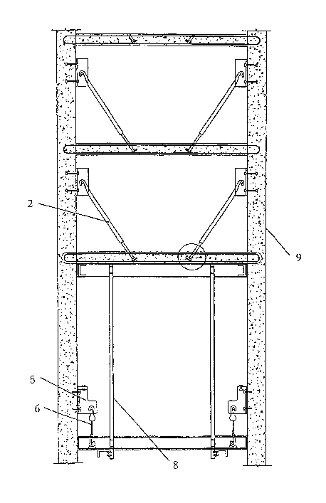
Referring to Fig. 2, a first plurality of positioning members 5 are
fixed at a height where a floor slab 3 is to be installed, and a floor slab
mould 4 is then installed on the first plurality of positioning members 5.
to Through a plurality of traction members 6, a supporting structure 8 is
hung on a lower end of the positioning member 5 and employed to
support the floor slab mould 4. The floor slab 3 is then to be cast by
pouring concrete into the floor slab mould 4. Before pouring concrete, a
plurality of tension rods 2 having a threaded head 10 at their lower end
is are obliquely inserted, from the above, into the floor slab mould 4 in a
manner that upper hook ends of the tension rods 2 are hung on a plurality
of load-bearing members that are mounting members 1 on the wall 9 (as
shown in Figs. 2 and 7). After the concrete is poured and cured to a
certain extent, a second plurality of positioning members 5 are re-
2o installed at a position of the lower floor, and the supporting member 8
and the floor-slab mould 4 are connected to the second plurality of
positioning members 5 through the traction members 6. The floor slab 3,
after being cast, is pulled by plural tension rods 2. Then the mounting
7
CA 02473755 2004-07-20
members 1 is dismantled, after the floor slab 3 is cured, and the tension
rods 2 are taken away while leaving the threaded head 10 in the floor slab
mould 4. The holes left during the installation of the floor slab are filled
up with cement.
s Referring to Fig. 3, the first plurality of positioning members 5
are dismantled before casting the next lower floor slab, so that the
supporting frame 8 and the floor slab mould 4 are loaded on the second
plurality positioning members 5. With reference to Figs. 4 and 5, under
the effect of gravity and by the aid of the traction of the traction member
l0 6, the floor slab mould 4 is lowered on the second mounting member 5.
After that, the installation for the next lower floor is to be carried out.
Referring to Figs. 8, 9 and 10, which show an erection unit in
accordance with a second embodiment of the present invention, the
traction members 2 in this embodiment are hook-like tension rods. After
Is installation of the floor slab mould 4 and the steel bar, an end of each of
the hook-shaped tension rods 2 is inserted in the floor slab 3 and folded
to into an angle, and another end of each of the tension rods 2 is folded
into a hook and connected to the steel bar 9' on the wall 9. The tension
rod 2 is obliquely arranged.
2o Referring to Figs. 11, 12 and 13, which show an erection unit in
accordance with a third embodiment of the present invention, wherein a
plate 7 is soldered with a connecting rod 14 to create a "T"-shaped
mounting member that is to be inserted in the wall 9. A lower end of the
a
CA 02473755 2004-07-20
connecting rod 14 is formed with threads and protrudes out of the wall 9,
and alike, the connection between the traction member 6 and the floor
slab 3 is also achieved through the "T"-shaped mounting member formed
by the plate 7 and the connecting rod 14. The traction member 6 can be
s in the form of a sleeve 11 formed with threads.
The traction member shown in Figs. 11-13 is a tension rod 2,
both ends of the tension rod 2 are connected to the floor slab 3 and the
wall 9, respectively, via the plate 7. The plate 7 is threadedly connected
to the tension rod 2.
Referring to Figs. 14-16, which show an erection unit in
accordance with a fourth embodiment of the present invention, both ends
of the tension rod 2 in this embodiment are folded into a hook and
connected to the steel bars 3' of the floor slab 3 and to the steel bars 9'
on the wall 9, respectively. The tension rod 2 is threadedly connected to
~s the sleeve 11, so that the tension rod 2 can be tensioned~or released by
rotating the sleeve 11 in different directions.
Referring to Figs. 17 and 18, which show an erection unit in
accordance with a fifth embodiment of the present invention, a first end
of a reinforced bar 2' is inserted through the uncured floor slab 3, and a
2o second end of which is connected to the load-bearing member above the
uncured floor slab 3. In installation, the reinforced bar 2' passes through
the floor slab 3 before pouring concrete, and the concrete will inflate
after being solidified and will produce pressure effect on the reinforced
9
CA 02473755 2004-07-20
bar 2' . Since the reinforced bar 2' is formed with lines and grooves, when
the uncured floor slab 3 is a little deformed under the effect of gravity,
the friction force generated between the reinforced bar 2' and the
concrete will be greater enough to limit the deformation of the floor slab
s 3 within an acceptable range. When the load-bearing member above the
uncured floor slab 3 is connected to the truss of the mounting member, an
upper end of the reinforced bar 2' is connected to the truss while a lower
end of the reinforced bar 2' passes through the uncured floor slab 3. If the
traction member above the uncured floor slab 3 is the traction member
o serving to pull the next upper floor slab, namely a reinforced bar 2', then
the reinforced bars 2' are connected to each other by soldering methods,
and the soldering point is located above the respective floor slabs.
Referring to Figs. 19 and 20, which show an erection unit in
accordance with a sixth embodiment of the present invention, wherein
Is tlie~raction member in this embodiment is a steel cord 2", a first end of
which is connected to the uncured floor slab 3 through an upper drop
hanger 12, and a second end of which is connected to the load-bearing
member above the uncured floor slab 3. A lower end of the upper drop
hanger 12 is connected with a wedge block 13 having a small upper end
2o and a big lower end, the wedge block 13 passes through the floor slab 3.
A lower end of the wedge block 13 is connected with a lower drop
hanger 12 which is used to tighten the steel cord 2" by hanging weight,
so that, after pouring concrete, a pulling force can be produced to
io
CA 02473755 2004-07-20
counteract the weight of the uncured floor slab 3. When the load-bearing
member above the floor slab 3 is connected with the truss of the
positioning member, the upper end of the steel cord 2" is connected to
the truss, and the lower end of the steel cord 2" passes through the
s uncured floor slab 3 through the wedge block 13. If the load-bearing
member above the uncured floor slab 3 is the traction member of upper
floor slab, the steel cord 2" is able to pass through plural floor slabs in a
manner that the respective parts of the steel cord 22" are connected with
one another by the drop hanger 12 and the wedge block 13.
o Referring to Figs. 21 and 22, which show an erection unit in
accordance with a sixth embodiment of the present invention, the traction
member in this embodiment is an iron chain 2, and other components are
the same as the above-mentioned six embodiments, thereby, further
descriptions are omitted.
Is While we have shown and described various embodiments i-n~
accordance with the present invention, it should be clear to those skilled
in the art that further embodiments may be made without departing from
the scope of the present invention.
11