Note: Descriptions are shown in the official language in which they were submitted.
CA 02473899 2006-11-28
- 1 -
BACKGROUND OF THE INVENTION
The present invention relates to aerosol dispensing
devices, and in particular to valve assemblies that
provide automatic dispensing of aerosol content at
predetermined time intervals, without requiring the use
of electrical power.
Aerosol cans dispense a variety of ingredients.
Typically, an active is mixed with a propellant which
inside the can is at least partially in a gas state, but
may also be at least partially dissolved into a liquid
containing active. Typical propellants are a
propane/butane mix or carbon dioxide. The mixture is
stored under pressure in the aerosol can. The active
mixture is then sprayed by pushing down/sideways on an
activator button at the top of the can that controls a
release valve. For purposes of this application, the
term "active chemical" is used to mean that portion of
the content of the container (regardless of whether in
emulsion state, single phase, or multiple phase), which
is in liquid phase in the container (regardless of phase
outside the container) and has a desired active such as
an insect control agent (repellent or insecticide or
growth regulator), fragrance, sanitizer, and/or
deodorizer alone and/or mixed in a solvent, and/or mixed
with a portion of the propellant.
Pressure on a valve control button is typically
supplied by finger pressure. However, for fragrances,
deodorizers, insecticides, and certain other actives
which are sprayed directly into the air, it is sometimes
desirable to periodically refresh the concentration of
active in the air. While this can be done manually,
there are situations where this is inconvenient. For
example, when an insect repellant is being sprayed to
protect a room overnight (instead of using a burnable
CA 02473899 2006-11-28
- 2 -
mosquito coil), the consumer will not want to wake up in
the middle of the night just to manually spray more
repellant.
There a number of prior art systems for
automatically distributing actives into the air at
intermittent times. Most of these rely in some way on
electrical power to activate or control the dispensing.
Where electric power is required, the cost of the
dispenser can be unnecessarily increased. Moreover, for
some applications power requirements are so high that
battery power is impractical. Where that is the case,
the device can only be used where linkage to conventional
power sources is possible.
Other systems discharge active intermittently and
automatically from an aerosol can, without using
electrical power. For example, U.S. Pat. No. 4,077,542
relies on a biased diaphragm to control bursts of aerosol
gas at periodic intervals. See also U.S. Pat. Nos.
3,477,613 and 3,658,209. However, biased diaphragm
systems have suffered from reliability problems (e.g.
clogging, leakage, uneven delivery). Moreover, they
sometimes do not securely attach to the aerosol can.
Moreover, the cost of some prior intermittent spray
control systems makes it impractical to provide them as
single use/throw away products. For some applications,
consumers may prefer a completely disposable product.
However, many dispensing devices permit liquid with
active to pass through a variety of narrow control
passages in the valve. Over time, this can lead to
clogging of the valve, and thus inconsistent operation.
In U.S. Pat. No. 4,396,152 an aerosol dispensing system
was proposed which separately accessed the vapor and
liquid phases of the material in the container. However,
this device did not achieve reliable automatic operation.
CA 02473899 2006-11-28
- 3 -
Document JP 56 037070 - shows a valve assembly for
intermittently spraying product from an aerosol can. The
assembly has two conduits connecting to the interior of
the can. One leads to the product in the bottom of the
can. The other connects to the gas space at the top of
the can and leads to an accumulation chamber. As the
accumulation chamber fills a diaphragm releases pressure
from the axially remote side of the main valve for the
product. When the pressure reduces to below a critical
pressure, a main product valve opens. This results in a
burst of product exiting the device from the main nozzle.
Further filling of the accumulation chamber pulls a
diaphragm central stem fully away from the axially remote
end of the main valve and uncovers a dedicated discharge
passage for the propellant gas leading directly to
atmosphere.
Document JP 56 070865 - shows another intermittently
actuating valve for an aerosol can in which the can has
separate channels for propellant gas and product. The
propellant gas is fed via a control regulating valve
through a side feed conduit to the far side of a
diaphragm where it pressurizes the accumulation chamber.
The diaphragm presses a button, which in turn operates a
downstream main valve for the product. Actuation of the
main valve stem also opens an ancillary valve allowing
discharge of propellant gas from the accumulation chamber
to atmosphere.
Yet another prior art arrangement is shown in JP 57
174173. In this arrangement a can has a valve with two
stages of operation. A small movement allows only
propellant gas to exit via a gas outlet. Further
pressure allows product to exit via a product outlet.
When the valve assembly is affixed to the can, the valve
in the top of the can is actuated to the extent to allow
CA 02473899 2007-01-02
- 4 -
the propellant gas to enter a conduit where it leads to
the end of the assembly remote from the can. It passes
via a control valve to an accumulation chamber. When it
fills the accumulation chamber to a threshold pressure a
diaphragm flips and presses the top of a valve body which
presses further on the aerosol can valve allowing product
to escape. When this happens, a vent orifice opens to
allow the propellant gas in the accumulation chamber to
escape directly to atmosphere.
Thus, a need still exists for improved, inexpensive
automated aerosol dispensers that do not require
electrical power.
BRIEF SUMMARY OF THE INVENTION
In one aspect the invention provides a valve
assembly suitable to dispense an active chemical from an
aerosol container where the container has a first region
holding a gas propellant and a second region holding an
active chemical. The assembly is of the type that can
automatically iterate between an accumulation phase where
the gas is received from the container, and a spray phase
where the active chemical is automatically dispensed at
intervals. The regions need not be physically separated
from each other. In fact, the preferred form is that the
first region be an upper region of the can where
propellant gas has collected above a liquid phase of the
remainder of the can contents.
There is a housing mountable on an aerosol
container. A movable diaphragm is associated with the
housing and linked to a seal, the diaphragm being biased
towards a first configuration. An accumulation chamber
is inside the housing for providing variable pressure
against the diaphragm. A first passageway in the housing
is suitable for linking the first region of the aerosol
container with the accumulation chamber, and a second
CA 02473899 2007-01-02
- 5 -
passageway links the second region with an outlet of the
valve assembly.
When the diaphragm is in the first configuration the
seal can restrict the flow of active chemical out the
valve assembly. When the pressure of chemical inside the
accumulation chamber exceeds a specified threshold, the
diaphragm can move to a second configuration where the
active chemical is permitted to spray from the valve
assembly.
In preferred forms a porous material is disposed
within the first passageway to regulate the flow rate of
gas propellant there through. The diaphragm shifts back
to the first configuration from the second configuration
when pressure of the gas propellant in the accumulation
chamber falls below a threshold amount.
The accumulation chamber will exhaust the gas when
the diaphragm is in the second configuration. The gas
propellant and active chemical mixes in the valve
assembly outside of the can.
There may also be a container that is linked to the
valve assembly, and an actuator portion of the housing
that rotates to allow gas propellant to leave the
container and enter the first passageway. The seal may
be displaceable in an axial direction to allow gas
propellant to flow through the first passageway into the
accumulation chamber.
Methods for using these valve assemblies with
aerosol containers are also disclosed.
The present invention achieves a secure mounting of
a valve assembly on an aerosol can, yet provides an
actuator that has two modes. In one mode the valve
assembly is operationally disconnected from the actuator
CA 02473899 2006-11-28
- 6 -
valve of the aerosol container (a mode suitable for
shipment or long-term storage). Another mode
operationally links the valve assembly to the aerosol
container interior, and begins the cycle of periodic and
automatic dispensing of chemical there from.
Importantly, periodic operation is achieved without
requiring the use of electrical power to motivate or
control the valve.
The valve assembly has few parts, and is inexpensive
to manufacture and assemble. Moreover the separate
accessing of the gas propellant lets the gas (as
distinguished from more viscous liquid) motivate the
diaphragm and thus provides for cleaner and more reliable
operation. By not requiring liquid and vapor to both
pass through the porous media, there is much less
likelihood for clogging due to extended use over months.
Using the separation concepts described in this patent,
product is released under full pressure with liquid
propellant (as in a typical manually operated aerosol
can), so as to provide for very effective particle break-
up. If in a device like the present one the propellant
gas was not separated from the main product, it might
separate in the accumulation chamber or elsewhere in the
device, thereby providing inconsistent results.
The foregoing and other advantages of the invention
will appear from the following description. In the
description reference is made to the accompanying
drawings which form a part thereof, and in which there is
shown by way of illustration, and not limitation,
preferred embodiments of the invention. Such embodiments
do not necessarily represent the full scope of the
invention, and reference should therefore be made to the
claims herein for interpreting the scope of the
invention.
CA 02473899 2006-11-28
- 7 -
BRIEF DESCRIPTION OF THE DRAWINGS
FIG. 1 is a sectional view of an automatic
dispensing valve assembly in an "off" configuration;
FIG. 2 is a view similar to FIG. 1, but with the
valve in an "on" configuration during the accumulation
phase of the dispensing cycle;
FIG. 3 is an enlarged view of a part of the valve
assembly of FIG. 1;
FIG. 4 is a view similar to FIG. 3, but with the
valve in the spray phase of the dispensing cycle;
FIG. 5 is a sectional view of an automatic
dispensing valve assembly embodying the present invention
in an "off" configuration;
FIG. 6 is a view similar to FIG. 5, but with the
valve in an "on" configuration during the accumulation
phase of the dispensing cycle;
FIG. 7 is a sectional view of an automatic
dispensing valve assembly of another embodiment in an
"off" configuration;
FIG. 8 is a view similar to FIG. 7, but with the
valve in an "on" configuration during the accumulation
phase of the dispensing cycle;
FIG. 9 is a view similar to FIG. 8, but with the
valve assembly in the spray phase;
FIG. 10 is an enlarged view of a gas propellant
control valve of the valve assembly illustrated in FIG.
7; and
FIG. 11 is another enlarged view of the gas
propellant valve of the valve assembly illustrated in
FIG. 8, with the valve in a different configuration.
DETAILED DESCRIPTION OF THE PREFERRED EMBODIMENT
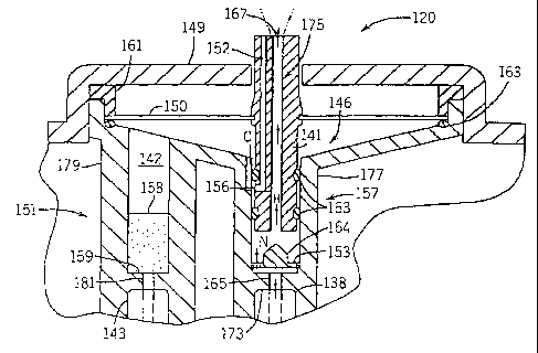
Referring to FIG. 1, a dispenser 120 is mounted onto
can 122 via outer wall 144 that has a threaded inner
surface so as to intermesh with threads on the outer
CA 02473899 2006-11-28
- 8 -
surface of wall 136. A cover 149 extends substantially
radially inwardly from the axially outer end of wall 144.
Wall 136 has a flange at its axially inner surface that
engages can chime 139. Wall 136 is integrally connected
to an angled wall 147 that extends radially inwardly, and
axially downstream, there from. Wall 147 is integrally
connected at its radially inner edge to wall 154 that
extends axially upstream and has a flange that engages
rim 129.
Control assembly 120 further includes a lever 171
that is rotated along with wall 144 to displace the
control assembly 132 in the axial direction, as described
above. Additionally, lever 171 could include a
perforated tab (not shown) between itself and wall 144
that is broken before the dispenser can be actuated,
thereby providing means for indicating whether the
dispenser has been tampered with.
Can 122 includes first and second valves 137 and
140, respectively, that extend into can 122. Valve 137
is connected to a conduit 133 that extends axially
towards the bottom of the can so as to receive the
chemical mixture. Valve 140 terminates in the upper
region 135 of can 122 so as to receive gaseous
propellant. Valves 137 and 140 includes a downwardly
actuatable conduit 138 and 143, respectively, that extend
axially out of the can 122. Accordingly, dispenser 120
may be provided as a separate part that is mountable onto
can 122 by rotating wall 144 with respect to wall 136.
Referring to FIG. 3, active valve assembly 157
includes an annular wall 177 whose axially inner end
slides over conduit 137. A flange 173 extends radially
inwardly from wall 177, and engages the outer end of
conduit 138. Flange 173 defines a centrally disposed
channel 165 that extends axially there through and
CA 02473899 2006-11-28
- 9 -
aligned with conduit 138. An annular wall 141 fits
inside wall 177 and extends axially downstream from
flange 173, and defines an axially extending conduit 175
that is in fluid communication with channel 165. Channel
165 extends out the dispenser 120 to provide an outlet
167 to the ambient environment. Wall 141 further defines
a second channel 152 that extends axially between a
propellant outlet vent 156 and the ambient environment.
A plug 164 is disposed between channels 175 and 165,
and blocks channel 165 so as to prevent the active
chemical from exiting from the dispenser 120 when not in
the spray phase. A pair of o-rings 163 are disposed
between the inner surface of wall 177 and the outer
surface of wall 141 to further ensure that no active
chemical or propellant is able to exit dispenser 120
through vent 156 that extends through wall 141. An
annular channel 153 surrounds plug 164 and joins channels
165 and 175 in fluid communication during the spray
phase, as will be described in more detail below.
The propellant valve assembly 151 includes an
annular wall 179 defining a conduit 142 that extends
axially from valve stem 143 into an accumulation chamber
146. Accumulation chamber is defined by a diaphragm 150
that extends radially from a wall 161 that is disposed at
the interface between cover 149 and the axially outer end
of wall 179, axially inner portion of wall 161, inner
surface of wall 179, and outer surface of wall 141.
Diaphragm 150 is further connected at its radially inner
end to wall 141.
Wall 179 includes a flange 159, similar to flange
173 of wall 177, that engages valve stem 143, and defines
a channel 181 extending there through that joins valve
stem 143 and conduit 142 in fluid communication. A
porous flow control media 158 is disposed within channel
CA 02473899 2006-11-28
- 10 -
142 axially downstream from flange 159 so as to regulate
the flow of propellant into accumulation chamber 146.
When the dispenser 120 is initially mounted onto can
122, neither conduit 138 or 143 are actuated. However,
referring now to FIG. 2, once the dispenser 120 is
rotated to the "ON" position, thereby beginning the
accumulation phase, flanges 159 and 173 are translated
axially upstream and depress valve stems 143 and 138,
respectively. Active chemical thus travels through
conduit 133, valve 137, and into conduit 165. The active
is prevented, however, from flowing into conduit 175 by
the seal provided by plug 164 and o-rings 163.
The propellant travels through valve 140, channel
181, porous media 158, conduit 142, and into accumulation
chamber 146. Once the pressure of propellant acting on
the axially inner surface of diaphragm 150 exceeds a
predetermined threshold, the diaphragm becomes deformed
from the normal closed position illustrated in FIG. 9 to
the open position illustrated in FIG. 4.
This initiates a spray phase, during which the
diaphragm 150 causes wall 141 to become displaced axially
upstream, thereby removing the inlet to channel 175 from
the plug 164. Accordingly, active chemical flows along
the direction of arrow N from conduit 138, through
channel 153, and into conduit 175 where it exits the
dispenser 120 at outlet 167. Additionally, when wall 141
is displaced, the outer o-ring is removed from the inner
surface of wall 141.
As a result, propellant travels from accumulation
chamber 164 through the gap formed between the radially
inner surface of wall 177 and the radially outer surface
of wall 141 along the direction of arrow 0, through
channel 156, and into channel 152 where it exits the
dispenser as a separate stream. Once the pressure within
CA 02473899 2006-11-28
- 11 -
accumulation chamber 146 abates, the diaphragm snaps back
to the closed position to begin a subsequent accumulation
phase.
Referring next to FIG. 5, a dispenser 220 is
illustrated in accordance with the invention but having
otherwise a similar construction to that described above.
The primary other differences reside in the active valve
assembly 257 and propellant valve assembly 251.
In particular, the active valve assembly 257
includes an annular lip 225 that extends axially upstream
into conduit 233, and defines and interior cavity 224.
The axially upstream end of lip 225 fits inside conduit
233 to deliver active to valve 237.
The propellant valve assembly 251 includes a
flexible seal 234 extending radially outwardly from
member 225 such that the axially outer surface of seal
234 rests against the axially inner surface of a seat
254. Seat 254 is disposed within the cup 234, and
receives inner and outer fork members 259 therein. Fork
259 defines the axially inner end of a wall 279 that
encloses a conduit 242 that flows into accumulation
chamber 246. A porous flow control media 258 is disposed
within conduit 242.
When the dispenser is in the "OFF" position
illustrated in FIG. 5, seal 234 prevents propellant from
entering channel 242. However, referring to FIG. 6, when
assembly 232 is further rotated to switch the dispenser
"ON," fork members 259 are displaced axially upstream
against seal 234 which deflects outwardly away from seat
254. Because inner fork member is displaced axially
downstream from outer fork member, the inlet to channel
242 is exposed to upper portion 235 of can 222, thereby
enabling propellant to enter accumulation chamber 246 via
conduit 242.
CA 02473899 2006-11-28
- 12 -
Referring next to FIGS. 7-10, a dispenser 520 is
mounted onto a can 522 in accordance with a second
embodiment. A more conventional container exit valve 537
extends upwardly from the center of the valve cup 527.
The valve 537 has an upwardly extending valve stem 538,
biased outwardly by a spring 569, through which the
active mixture of the can 522 may be expelled. Valve 537
is shown as a vertically actuated valve, which can be
opened by moving the valve stem 538 directly downwardly.
Instead, one could use a side-tilt valve where the valve
is actuated by tipping the valve stem laterally and
somewhat downwardly.
Control assembly 532 includes an outer wall 544
threaded on its inner surface that intermesh with threads
of wall 536 that is connected to the can chime 539.
Accordingly, the user may rotate wall 544 to switch the
dispenser between the "OFF" position (FIG. 7) and the
"ON" position (FIG. 8)
Wall 544 is supported at its axially outer end by
wall 552 that receives, in a groove disposed at its lower
end, the upper end of a retainer wall 541. An o-ring 563
is disposed at the interface between walls 552 and 541.
A monostable, flexible diaphragm 550 extends radially
from the interface between the o-ring 563 and wall 552.
0-ring 563 thus provides a seal to prevent gas from
escaping from the accumulation chamber 546 during the
accumulation phase. Wall 541 further includes a flange
543 extending axially downstream towards diaphragm 550.
An inverted "L" shaped wall 561 is attached to the inner
surface of diaphragm 550, and receives the axially outer
end of flange 543 to prevent the escape of gas propellant
during the accumulation phase.
Referring in particular to FIG. 10, dispenser 520
also includes a gas propellant valve assembly 551 and an
CA 02473899 2006-11-28
- 13 -
active valve assembly 557. The gas propellant valve
assembly 551 includes wall 541, which defines a void that
is occupied by a porous media 558. A plunger 556 having
a tip 559 is disposed within a seat 554 axially upstream
of the porous media 558. Seat 554 is affixed to the cup
527. Plunger 556 is annular, and defines a channel 553
extending there through at a location axially downstream
from tip 559. Channel 535 defines the mouth of
accumulation chamber 546.
A flexible seal 534 extends radially outwardly from
tee 525 such that it rests against the axially inner
surface of seat 554. Two seals thus prevent the gas
propellant from entering accumulation chamber 546 when
the dispenser is "OFF." Seal 534 minimizes leakage
during filling of the can and provides a redundant seal
to the plunger. Channel is in radial alignment with seat
554, thus forming a seal to prevent gas propellant from
entering into the plunger.
An active valve assembly 557 (see Fig. 7) includes a
hub 515 that is formed from the radially inner surface of
annular retainer wall 541. The hub defines a channel 569
through which the active mixture flows from the valve
stem 538 during a spray phase. A plug 564 is attached to
the axially inner surface of diaphragm 550, and extends
axially inwardly to seal channel 569, thus preventing
active chemical from exiting the dispenser 520 during the
accumulation phase. An annular opening 567 is disposed
in the diaphragm 550 at a position adjacent the plug 567
to enable active chemical to flow from the hub and out
the dispenser 520 during the spray phase, as will be
described below.
When the control assembly 532 is rotated to switch
the dispenser 520 to the "ON" position, the accumulation
phase begins. In particular, wall 541 and plunger 556
CA 02473899 2006-11-28
- 14 -
are biased downwardly such that tip 559 deflects seal 534
away from the seat 554 in the direction of arrow H. The
plunger 556 is depressed such that channel 553 is
translated to a position axially upstream of seat 554,
thereby permitting pressurized gas propellant to enter
the channel 553 along the direction of arrow I.
Plug 564 is biased against hub 565, which depresses
valve stem 538, thereby pressurizing active chemical
against the plug. The seal formed between the plug 564
and hub 565 prevents any active chemical from exiting the
dispenser during the accumulation phase.
The gas propellant travels through the porous media
and into inlet 560 of the accumulation chamber 546. The
constant supply of gas propellant flowing into the
accumulation chamber 546 causes pressure to build
therein, and such pressure acts against the inner surface
of diaphragm 550. Once the accumulation chamber 546 is
sufficiently charged with gas propellant, such that the
pressure reaches a predetermined threshold, the mono-
stable diaphragm 550 becomes deformed from the normal
closed position illustrated in FIG. 28 to the open
position illustrated in FIG. 9.
This initiates the spray phase, during which the
diaphragm 550 is biased axially downstream, thereby also
biasing plug 564 axially downstream. An outlet channel
is thus formed between plug 564 and hub 565 that permits
the pressurized active material to flow along the
direction of arrow J out the dispenser 520 into the
ambient environment as a "puff." Furthermore, wall 561
is translated axially downstream of flange 543, thereby
allowing the gas propellant stored in the accumulation
chamber 546 during the previous accumulation phase to
travel along the direction of arrow K, mix with the
active chemical, and exit the dispenser 520.
CA 02473899 2006-11-28
- 15 -
Because the channel 553 is disposed below seat 554
during the spray phase, gas propellant continues to flow
into the accumulation chamber 546. However, because more
propellant exits accumulation chamber 546 than the
propellant entering, the pressure within the accumulation
chamber quickly abates during the spray phase. Once the
pressure within chamber 546 falls below a predetermined
threshold, the diaphragm 550 snaps back to its normal
position, re-establishing the seal between plug 564 and
channel 569. The propellant continues to flow into the
accumulation chamber 546 to initiate the next spray
phase.
The above description has been that of preferred
embodiments of the present invention. It will occur to
those that practice the art, however, that many
modifications may be made without departing from the
scope of the invention as defined in the following
claims.
Industrial Applicability
The present invention provides automated dispenser
assemblies for dispensing aerosol can contents without
the use of repeated electric power or manual activation.