Note: Descriptions are shown in the official language in which they were submitted.
CA 02474133 2004-O1-23
Fluctuating gear ratio limited-slip differential
Description
BACKGROUND OF THE INVENTION
1. Field of the Invention
This invention relates to limited-slip differentials for wheeled vehicles,
particularly
to relates to a type of fluctuating gear-ratio limited-slip differential.
2. Backgmund of Related Art
Limited-slip differentials are well known and take different forms; the
working
principle can be divided into inner friction model, overrunning model,
electronic
controlled automatic differential locker, the limited slip function realized
using ABS
brake system, and potential barrier model. Each model has some defects.
For inner friction model, which is the most widely used model of limited slip
Zo differentials, can be subdivided into preloasied and non-preloaded, both
have the
defects of higher price, and the latter may be even more expansive, while the
former
may leads to a higher steering resistance and increased tire wear.
The overrunning model has complicated structure, works roughly, and some types
have a lower reliability.
The electronic automatic differential locker also works roughly, being
complicated in
structure.
3o The limited-slip function realized by ABS system consumes more power.
This patent reveals a type of limited-slip differential belonging to potential
barrier
model, having the advantage of simple structure, higher reliability and true
traction.
The function is realized by periodic change in gear ratio between the pinions
and the
side gears, and the pinions have an odd number of fhe gear ratio fluctuating
period in
one revolution, so that when the gear ratio between the pinions and one side
gear
reaches the maximum, the gear ratio between the pinions and the other side
gear gets
the minimum, thus an unequal distribution of the torque on two side gears is
realized.
2
CA 02474133 2004-O1-23
If the pinions rotate as angle of a half period of the speed ratio
fluctuation, the torque
distribution on both side gears is interchanged. The periodic change in the
torque bias
ratio forms two potential barriers, if the ratio of the torque acted on side
gears does
not reach the maximum torque bias ratio, the differential cannot make a
continuous
differential rotation, thus the slip of the driving wheel is limited. But up
to now for
available product, the period of the speed ratio fluctuation is only ane
pitch. In each
pitch the pinions and the side gears will undergo a process of relative
angular
acceleration and deceleration, the relative angular acceleration is rather
higher, tire
value is proportional to the changing range in gear ratio, and proportional to
the
l0 square of the number of speed ratio periods involved in one revolution of
the pinions.
A larger relative angular acceleration will lead to higher relative curvature
between
tooth surfaces and lower load capacity, tends to snake noise. Although the
fluctuating
range in gear ratio can be improved to a certain extent by means of
optimization, the
effect is limited. A further increment in the range of gear ratio will lead to
a rapid
a5 increment in relative curvature between tooth surfaces, or even generate an
edge an
tooth surfaces. According to traditional design method of one-pitch period,
the
maximum speed ratio resulted in dit~erential movement between two side gears
is
only 1;1.38 for a gear pair of 7 teeth in a pinion and 12 teeth in a side
gear, and the
speed ratio is reduced to I :1.31 for a gear pair of 9 teeth in pinion and 12
teeth in side
2o gears, it is not sufficiem for the requirement of off road vehicles.
SUMMARY OF THE INVENTION
The object of the present invention is to provide a type of limited slip
differential
25 characterized by larger fluctuating raage in gear ratio and higher torque
bias ratio,
which can greatly improve the cross-country ability when one of the driving
wheels is
running an icy-snow mad surfaces.
To realize the object, the technical scheme of the present invention is a type
of
30 fluctuating gear-ratio limited-slip differential, by means of periodic
fluctuation in the
gear ratio between the planet and side gears, the torque distribution between
two side
gears becomes a periodic function of the angle of rotation of the planet
gears, so that
the slip on one side of the driving wheels is limited. The differential mainly
comprises
a differential case, a cross or straight pinion shaft fixed within the
differential case,
35 plural pinioas, and a pair of side gears situated within ~e differential
case engage
with the pinion gears with fluctuated gear ratio, and the period of the gear
ratio
between the pinion and side gears involves at least two pitches, and the
number of
pitches involved in each period are corresponding to the common factor in the
number
CA 02474133 2004-O1-23
of teeth in both pinion and side gears. Each period of the gear ratio
fluctuation
involves a group of teeth, and the number of teeth involved in each group are
corresponding to the number of pitches involved in each period, the combined
working range of the teeth involved in each group covers the whole working
range of
both the pinions and side gears involved in a period of gear ratio, and for
each group
of the same gear the corresponding teeth have the same structure.
The working range far each tooth in each group can be determi~d in design
process,
and there is a small ovtrlap in working range between adjacent tooth pairs.
i0
For preferred scheme of the invention, the number of pitches involved in each
gear
ratio period is 3, therefore the numbers of teeth in both pinion and side
gears are
multiples of 3. The adjacent three teeth involved in each group are
successively a
lower tooth, a higher tooth and another lower tooth with the same tooth height
of the
i5 above lower one. Between a higher tooth and a lower tooth is a shallowee
tooth
groove, and between two lower teeth is a deeper tooth groove.
Far another preferred scheme of the invention, the three teeth involved in
each group
are successively a higher tooth, a lower tooth and another higher tooth with
the same
20 tooth height of the above higher one. Between a higher tooth and a lower
tooth is a
deeper tooth groove, and between two higher teeth is a shallower tooth groove.
The pinions have an odd number of tooth groups, so that when the gear ratio
between
the pinions and one side gear reaches the maximum, tyre gem ratio between the
pinion
2S and the other side gear reaches the minimum. The group number in side gears
is a
multiple of the number of planet gears, sa that each pinion works at the same
phase
angle.
The said gear ratio is a function as follows:
m
30 ~cz~ ~ ii ~-C~rat~sin(az~tz>~3)+C~(1-rat)~sin(a=~~cz~)~
where az denotes the number of teeth in side gears, zz is the number of teeth
in
pinions, ~c'~ represents the angle of rotation of the side gear, while ~czs
indicates the
angle of rotation of the pinions. The range of the number of teeth z, in side
gears is 9,
12, 15 and 18; while the range of the numbers of teeth in pinions az is 9 and
1 ~; the
35 codomain of C is 0.2 to 0:4; while the codoraain of rat is 0.7 to 1Ø
The lower part of the profiles of the lrevel gear pair with fluctuating gear
ratio, i.e.
d
CA 02474133 2004-O1-23
beneath the pitch tine is some analytic curve, while the upper p$rt, i.e.
above the pitch
line is a conjugate profile of the analytic curve profile of the tooth that
matches with,
which is determined point by point based on the theorem of engagement that the
relative speed betw~n the tooth surfaces is perpendicular to the normal of the
analytic
tooth pm$le at the point. When the conjugate profile is in contact with the
analytic
pmiile, the relative movement between the gear pair can meet the equation as
follows:
rn
d~~2~ = z~ ~-C~rat~sin(z,~c'~I3)tC~(1-rat)~sin(zZ ~~«~)j
where z, denotes the number of teeth in side gears, z, is the number of teeth
in
pinions, ~~'~ represents the angle of rotation of the side gears, while ~~z~
indicates the
to angle of rotation of pinions. The codomain of C is from 0.2 to 0.4, while
the
codomain of rat is from 0.7 to 1Ø The range of the number of teeth z, in
side gears
is 9,12, 15 and 18; while the range of the number of teeth to in planet gear
z2 is 9 and
15. The analytic curve is a combination of straight line, circular and
elliptical arcs,
invoIute and logarithmic spiral. Since each pair of teeth in a group has an
individual
working range, each tooth in a group has its individual pmflle.
The principle of present invention is that the period of the gear ratio is
increased to at
least twa pitches, thus in comparison to traditional design method, the number
of the
periods of the gear ratio fluctuation involved in one revolution of the pinion
is
2o reduced to one half or less, thus the speed ratio fluctuating range can be
substantially
increased while the relative angular acceleration between the pinion and side
gears
can be reduced at the same time.
In comparison with previous technologies, the distinguished advantages of the
invention is described as follows:
The differential described in present patent is a type of fluctuating gear-
ratio
differential, the gear ratio fluctuates during the process of the engagement
between the
pinion and side gears, and the period of speed ratio fluctuation is increased
to two
pitches or higher, thus the speed ratio fluctuating range can be substantially
increased
while the relative angular acceleration between the pinions and side gears can
be
reduced at the same time.
For preferred embodiments, the present invesztion is a type of three-pitch
flucturtting
transmission-ratio differential, the gear ratio fluctuates during the grocers
of the
engagement between the pinion and side gears, and the period of speed ratio
fluctuation is three pitches. Since the speed ratio fluctuation period is
increased to
s
CA 02474133 2004-O1-23
three pitches, the relative angular acceleration between the pinions and side
gears is
greatly reduced, and the phenomenon of forming an edge on tooth surfaces will
not
happen even if the range of speed ratio between side gears is increased to
1:1.85.
Because of the increment in speed ratio range, the height of potential barrier
to the
differential rotation is enhanced; meanr hile the range of the angle of
rotation of the
pinions corresponding to larger torque bias ratio is enlarged, the width of
the potential
barrier is also enlarged, which reduces the possibility of the pinions drive
over the
potential barrier caused by occasional vibration, and the reliability of anti-
slip is
improved. In this way, the torque bias ratio of the differential is
substantially
increased.
BRIEF DESCRIPTION OF DRAWINGS
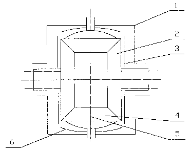
FIG. 1 is a schematic section view of the differential according to present
invention;
FIG. 2 is the drawing to show the structure of the side gear of the present
inventions;
FIG. 3 is the drawing to show the structure of the pinion of the present
inventions;
2o FIG. 4 is the drawing to show the structure of the side gear in another
embodiment of
the present inventions;
FIG. 5 is the drawing to show the structure of the pinion in another
embodiment of the
present inventions.
DETAILED DESCRIPTION OF PREFERRED EMBODIMENTS
A further detailed description of present invention is given as follows in
combination
with embodiments and drawings:
Embodiment 1:
The structure of the embodiment is illustrated in figures 1, 2 and 3. The
fluctuating
gear-ratio differential according to the present inventions involves a
differential case
1, a pinion shaft 5, either a cross or straight shaft, fixed inside the
differential case 1,
the pinion gears 4 and a pair of side gears 2, spherical thrust washers 6
situated
between the back sides of the pinion gears 4 and the differential case 1, flat
thrust
washers 3 situated between the back sides of the side gears 2 and the
differential case
6
CA 02474133 2004-O1-23
I, said pinion gears 4 and side gears 2 compose plural gear pairs.
For Embodiment 1, the number of teeth in both pinion gears 4 and side gears 2
are
chosen to be multiples of 3, during the engagement, the sped ratio fluctuates
with a
period of three pitches, thus in each period of the fluctuation in speed
ratio, a gmup of
three adjacent pairs of teeth.are involved, each of them has individual
profile. Within
a group of three teeth, each one has its individual working range, therefore
the tooth
height changes within the group, and each one has its individual profile.
to For the same gear, the corresponding teeth in each group have the same
profile and
tooth height. The pinion gears 4 have an odd tooth groups, thus when the gear
ratio
between the pinion gears 4 and one side gear 2 reaches the maximum, the gear
ratio
between the pinion gears 4 and the other side gear 2 gets the minimum, in this
way a
maximum torque bias ratio between two side gears can be obtained. The number
of
13 tooth groups in side gears 2 is a multiple of the number of pinion gears 4,
so that each
pinion gears 4 works at the same phase angle, thus the kinematicaI
interference
between the pinion gears 4 and side gears 2 is avoided.
For Embodiment I, the range of the number of teeth in side gears 2 is 9, 12,
15 and
20 18; while the range of the number of teeth in pinions 4 is 9 and I5. The
said three
teeth involved in a group are successively a lower tooth, a higher tooth and
another
lower tooth of the same height of the said lower one. For side gears 2,
between a
higher tooth ? and a lower tooth 8 is a shallower tooth grnove 9, and between
two
lower teeth 8 is a deeper tooth groove 10. For pinion gears 4, between a
higher tooth
25 13 and a lower tooth 14 is a shallower tooth groove 12, and between two
lower teeth
14 is a deeper tooth groove 11.
The working principle of Embodiment 1 is that the period of gear ratio
fluctuation is
increased to three pitches, so that the times of the change of gear ratio in
one.
3o revolution of the pinion is reduced to one third in comparison with
traditional design
method, thus the speal ratio fluctuating range can be substantially increased
while the
relative angular acceleration between the pinions and side gears can be
reduced at the
same time. Therefore the object of the present invention is achieved.
3s The gear ratio fluctuates in a function as follows:
n>
d~~=~ = Z' ~ -C ~ rat ~ sin(zz~«~ I3) + C . (1- rat) ~ sin(z2 . ~(zyj
where ~°~ represents the angle of rotation of the side gear, while ~b«~
indicates the
CA 02474133 2004-O1-23
angle of rotation of the pinions. For preferred embodiments, the codomain of C
is 0.2
to 0.4; while the codomain of rat is 0.7 to 1.0, and the speed ratio between
two side
gears fluctuates within 0.5 to 2Ø
The profile design is based upon the given transmission ratio of the gear
pair. Having
given the profiles of one member of the gear pair, the profiles of the other
member
can be determined point by point according to the theorem of engagement that
the
relative speed between the tooth surfaces is perpendicular to the normal of
the given
profile at the point. During the design process, it should be ensured that all
profiles are
to convex curves, each tooth has a suitable top land width and root width, and
there
exists a suitable overlap between adjacent tooth pairs. The design method for
present
invention is described as follows: the lower part of the profile, i.e. beneath
the pitch
line is a simple analytic curve, which is a combination of straight line,
circular and
elliptical arcs, while the upper part, i.e. above the pitch line is a
conjugate profile of
the analytic curve profile of the tooth that match with, which is determined
point by
point based on the theorem of engagement that the relative speed between the
tooth
surfaces is perpendicular to the normal of the analytic tooth profile at the
point.
Some parameters and experimental results of the samples for Embodiment I are
listed
2o as follows:
Torque
Embodiment ~ sped ratio
range
z z C rat big
' 2
example between side
gear
ratio
1 12 9 0.3-0.320.9-0.920.515-1.941 4.5-6:9
2 12 9 0.28-0.30.86-0.880.538-1.857 3.5-4.7
3 18 I5 0.18-0.20.93-0.950.667-1.500 2.7-3.0
The parameters and experimental results listed above are used to demonstrate
the
invention, not used as a limitation to the invention.
By means of reasonable choice the number of teeth in both pinion and side
gears to
get a common factor 3 in Embodiment 1, the period of the speed ratio is
designed to
be 3 pitches.
For present embodiment, the periodic fluctuation in the speed ratio between
two side
3o gears are utilized to form potential barriers to the differential rotation,
only when the
difference in the torque applied to two side gears is larger than the sum of
potential
barrier to the differential rotation and friction moment torque, can the
differential
CA 02474133 2004-O1-23
gears drive over the potential barrier to make continuous differential
rotation,
otherwise the differential gears can only swing within a period of speed
ratio, i.e.
three pitches.
Embodiment 2:
Figures l, 4 and 5 illustrate Embodiment 2 in accordance with the present
invention.
The structure, working principle and result of this embodiment are just the
same to
1o those of Embodiment l, being not describe here again.
The structure of the embodiment is illustrated in figures 1, 4 and 5. The
fluctuating
gear-ratio differential according to the present inventions involves a
differential case
I, a pinion shaft 5, either a cross or straight shaft, fixed inside the
differential case 1,
the pinion gears 4 and a pair of side gears 2, spherical thrust washers 6
situated
between the back sides of the pinion gears 4 and the differential case I, flat
thrust
washers 3 situated between the back sides of the side gears 2 and the
differential case
l, said pinion gears 4 and side gears 2 compose plural gear pairs.
2o For Embodiment 2, the number of teeth in both pinion gears 4 and side gears
2 are;
chosen to be multiples of 3, during the engagement, the speed ratio fluctuates
with a
period of three pitches, thus in each period of the fluctuation in speed
ratio, a group of
three adjacent tooth pairs are involved, each of them has individual profile.
Within a
group of three teeth, each one has its individual working range, therefore
each tootle
within the group has its individual profile and height. For the same gear,
the.
corresponding teeth in each group have the same profile and tooth height. The
pinion
gears have an odd tooth groups, and the number of tooth groups in side gears
is a
multiple of the number of pinion gears.
3o The difference between the present embodiment and the former one is that
the said
three teeth involved in a group are successively a higher tooth, a tower tooth
and
another higher tooth of the same height of the said higher one. For side gears
29
between a higher tooth 21 and a lower tooth 22 is a deeper tooth groove 24,
and
between two higher teeth 21 is a shallower tooth groove 23. For pinion gears
4,
between a higher tooth 25 and a lower tooth 26 is a deeper tooth groove 28,
and
between two higher teeth 25 is a shallower tooth groove 27.
The working principle of the present embodiment is just the same of the above
one,
9
CA 02474133 2004-O1-23
by means of increasing the period of speed ratio to three pitches, the times
of the
change in speed ratio involved in one revolution of the pinion gears 4 is
reduced to
one third of traditions! design method, thus the changing range in speed ratio
can be
substantially enhanced while the relative angular acceleration between the
pinion
gears 4 and side gears 2 is greatly reduced.
The principle and design method for Embodiment 2 are just the same of
Embodiment
1, being not described again.
0 The above figures and descriptions of Embodiment 2 are used to demonstrate
the
invention, not used as a limitation to the invention.
to