Language selection

Search

Patent 2474647 Summary

Third-party information liability

Some of the information on this Web page has been provided by external sources. The Government of Canada is not responsible for the accuracy, reliability or currency of the information supplied by external sources. Users wishing to rely upon this information should consult directly with the source of the information. Content provided by external sources is not subject to official languages, privacy and accessibility requirements.

Claims and Abstract availability

Any discrepancies in the text and image of the Claims and Abstract are due to differing posting times. Text of the Claims and Abstract are posted:

  • At the time the application is open to public inspection;
  • At the time of issue of the patent (grant).
(12) Patent Application: (11) CA 2474647
(54) English Title: METHOD FOR THE CREATION OF CLEARANCE HOLES
(54) French Title: PROCEDE POUR FACONNER DES TROUS DE DEGAGEMENT
Status: Deemed Abandoned and Beyond the Period of Reinstatement - Pending Response to Notice of Disregarded Communication
Bibliographic Data
(51) International Patent Classification (IPC):
  • A47B 96/14 (2006.01)
  • A47B 87/02 (2006.01)
(72) Inventors :
  • CRIACCI, MASSIMO (Italy)
(73) Owners :
  • MASSIMO CRIACCI
(71) Applicants :
  • MASSIMO CRIACCI (Italy)
(74) Agent: RICHES, MCKENZIE & HERBERT LLP
(74) Associate agent:
(45) Issued:
(86) PCT Filing Date: 2003-03-07
(87) Open to Public Inspection: 2003-10-02
Examination requested: 2008-02-22
Availability of licence: N/A
Dedicated to the Public: N/A
(25) Language of filing: English

Patent Cooperation Treaty (PCT): Yes
(86) PCT Filing Number: PCT/IT2003/000140
(87) International Publication Number: WO 2003079856
(85) National Entry: 2004-07-30

(30) Application Priority Data:
Application No. Country/Territory Date
RM 02 A 000160 (Italy) 2002-03-22

Abstracts

English Abstract


According to this invention, slots are made on the plane of any material; the
depth of these slots is equal to half the thickness of the plane, plus the
length of the radius of the stay bolt or stud to be entered, plus a tolerance
margin; the slots have the required length and are made on two or more sides
of the plane, in an alternate manner, so that the slot made on one side
overlaps by a few millimeters the slot made on the opposite side, creating in
such a way the space for the passage of a stay bolt and stud that serves as
the anchorage for the various pieces that make up to object to be realized.


French Abstract

L'invention concerne des trous de dégagement pouvant être façonnés à la surface d'un matériau quelconque. La profondeur de ces trous est égale à la moitié de l'épaisseur de la surface, plus la longueur du rayon du boulon ou du goujon à introduire, plus une marge de tolérance. Ces trous, d'une longueur donnée, sont façonnés en alternance sur deux côtés ou plus de ladite surface, de sorte que le trou disposé sur un côté chevauche de quelques millimètres le trou réalisé sur le côté opposé. Un espace est ainsi créé pour le passage d'un boulon ou d'un goujon servant d'ancrage à différents éléments constituant l'objet à réaliser.

Claims

Note: Claims are shown in the official language in which they were submitted.

7
CLAIMS
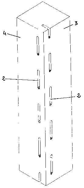
1. Method for the creation of clearance holes on a part being worked
(1), where there is a side (3) and a side (4) which are either
opposite or adjacent, characterized by the fact that a series of slots
(2) are alternatively made in succession and along an axis on the said
sides (3) and (4) of the part (1), once on side (3) and once on side (4)
of the said part, in such a way as to create a continuity between the
material taken off for the realization of the slots (2) on side (3) and on
side (4) and, in so doing, the removal of the material of the slots (2)
forms a clearance hole at the centre of the thickness of the part on
which the slots (2) have been made, and such a hole is useful for
the passage of studs or cables.
2. Method for the creation of clearance holes, according to the
preceding claim, characterized by the fact that the clearance hole has
the required length, while the depth of the slot is determined by half
the thickness of the part being worked, plus the radius of the stay
bolt or cable, plus the tolerance of the materials, and varies in relation
to the materials themselves.
3. Method for the creation of clearance holes, according to the
preceding claims, characterized by the fact that, if the slots are
created on adjacent sides of the part, it becomes feasible to make
clearance holes located close to the angles.

8
4. Method for the creation of clearance holes, according to the
preceding claims, characterized by the fact that the two ends of the
stud or cable (8) that acts as a stay bolt and is accommodated within
the clearance hole are threaded so that a terminal joining the parts
crossed by such a stud or cable may be screwed on these ends.
5. Method for the creation of clearance holes, according to the
preceding claims, characterized by the fact that the slots may be
made on any material whatsoever, so that the method allows to join
together parts that may also be made of different materials.

Description

Note: Descriptions are shown in the official language in which they were submitted.


CA 02474647 2004-07-30
WO 03/079856 PCT/IT03/00140
Method for the creation of clearance holes
Technical field
This invention related to a method to join together even different
materials through the creation of clearance holes allowing the entry of
stay bolts.
Background of art
It is common knowledge that the creation of a number of objects quite
often entails the recourse to junctions by means of tongue and groove
joint pins, eccentric joint pins, and L-shaped elements, made of
metal and other materials, adhesives, and so on.
The solutions outlined above have been adopted worldwide since time
immemorial, even though they are often inadequate from an
aesthetic point of view and, sometimes, they offer a poor resistance,
particularly to transverse stresses.
Besides, these solutions do not allow a great freedom of junction
among the parts, particularly when one wants to join together parts
with angles other than right angles.
Fundamentals of invention

CA 02474647 2004-07-30
WO 03/079856 PCT/IT03/00140
2
The subject of this invention is a method to join together even different
materials through the creation of clearance holes allowing the entry of
stay bolts.
According to this invention, slots are made on the plane of any
material. The depth of these slots is equal to half the thickness of the
plane, plus the length of the radius of the stay bolt or stud to be
entered, plus a tolerance margin.
The slots have the required length and are made on two or more sides
of the plane, in an alternate manner, so that the slot made on one side
overlaps by a few millimeters the slot made on the opposite side,
creating in such a way the space for the passage of a stay bolt and
stud that serves as the -anchorage for the various pieces that make up
to object to be realized.
Therefore, according to the method concisely described above, one
may create seats of unlimited length for the passage of stay bolts or
studs, while the thickness of the piece were the slots are made is
determined exclusively by the depth that the tool being used may
reach.
The detailed description provided below may allow an improved
understanding of what has been briefly said until now by making
reference to the attached drawings, where:
Brief description of the drawings
Figure 1 shows the front view of a rectangular element
worked according to the method of this invention.

CA 02474647 2004-07-30
WO 03/079856 PCT/IT03/00140
3
Figure 2 shows a schematic view of how the slots are made
on both sides of the part.
Figure 3 shows a cross section of a slot made according to
this invention.
Figure 4 shows an axonometric view of a part worked
according to this invention.
Figure 5 shows a section axonometric of a part worked
according to this invention.
Figure 6 shows an axonometric view of a part worked on an
angle according to this invention.
Figure 7 shows a section axonometric of a part worked on an
angle according to this invention.
Figure 8 shows a side view of a bookcase realized with a part worked
according to this invention.
Figure 9 shows a front view of the bookcase referred to in Figure 8.
Figure 10 shows a front section view of the bookcase referred to in
Figure 8.
Figure 11 shows a top view of the bookcase referred to in Figure 8.
Description of invention
With reference to these figures, the method for creating clearance
holes according to this invention is based on the realization, on two or
more sides of an element (1 ), for instance a wooden standard to be
used in a bookcase, of a series of slots (2) made alternatively in
succession on side (2) and on the opposite side (4) of the element (1 ),

CA 02474647 2004-07-30
WO 03/079856 PCT/IT03/00140
4
along an axis, in such a way as to create a hole that is the result of the
removal of material (3a), taken off from side (3) and the removal of
material (4a) taken off from the opposite side (4) (Figures 5-i ). The
clearance hole has the required length and its diameter is determined
by half the thickness of the part being worked, plus the radius of
the stay bold or cable, plus the tolerance of the materials that varies in
relation to the materials themselves.
The clearance holes) may be used in the assembly of the parts that
make up a piece of furniture such as, for instance, in the realization
of a bookcase for the passage of stay bolts that allow to make the
side of the bookcase an integral part of the shelves, without having to
resort to the traditional anchoring methods described above.
For instance, with reference to Figures 8, 9, 10, and 11, it may be
easily understood how the realization of the bookcase being shown
is extremely simplified by the presevce along the standards (6) of
the slots (2) that allow the passage of the stud (8).
The stud (8) allows the various sections of the standards (8) to form an
integral part supporting the shelves (9) and to reach the required
height even though, at least in the front part, nothing is visible.
Furthermore, the sturdiness of the system that is the subject
matter of this invention is determined both by the fact that, being the
stay bolts (8) accommodated inside the structure, they are protected
from any impact, and the fact that their position may not change by
chance depending on the stresses and size of the structure.

CA 02474647 2004-07-30
WO 03/079856 PCT/IT03/00140
Obviously, in order to see that the stay bolts (8) carry out their function
in the best possible manner, they shall be preferably provided with
threaded ends for screwing terminals (10) which are to allow the
adjustment of the tension of the stay bolts (8), even in relation to the
material used to realize the object or, at least, the structure, but
also in relation to the weight to be sustained and the use the
object is intended for.
As previously pointed out. Figures 6 and 7 clearly show that a
clearance hole may be created on an angle of the piece being worked,
making slots (2) close to the angle always according to the
arrangements described above.
In case of holes to be created in elements having a considerable
width, for instance beams, the slots may be realized alternatively on
each one of the four sides in such a way as to ensure the continuity in
the material being removed and, therefore, the creation of the hole for
the passage of the stud or reinforcement. A wooden beam for the
falsework of a roof may represent an example of such an application.
It is clear that the possibility of creating clearance holes on the pieces
to be assembled in order to accommodate cables or stay bolts of any
type and material allows the greatest possible freedom in the
realization, doing away with the design-related limitations that are
currently imposed by the customary means of aggregation and
assembly such as shelves, adhesives, tongue and groove joint pins,
and so on.

CA 02474647 2004-07-30
WO 03/079856 PCT/IT03/00140
6
The recourse to the aforementioned method, for instance, makes it
both feasible and easy to realize an orientation in the assembly of the
standard with respect to the shelf plane that is above or below 90,
allowing in such a way the realization of bookcases or pieces of
furniture where the design is not constrained by a right angle.
A further advantage that results from the application of the
aforementioned method is that, being realizable on any material,
including for instance Perspex, metal, wood and such artificial
materials as plastics, it allows a joint to be made with no resulting
problem due to the different materials being used.
It is evident that even though a likely application of the method was
suggested with reference to the realization of a bookcase, this should
not be construed as a limitation to the likely fields of use of this method
as it was merely provided as an example.

Representative Drawing
A single figure which represents the drawing illustrating the invention.
Administrative Status

2024-08-01:As part of the Next Generation Patents (NGP) transition, the Canadian Patents Database (CPD) now contains a more detailed Event History, which replicates the Event Log of our new back-office solution.

Please note that "Inactive:" events refers to events no longer in use in our new back-office solution.

For a clearer understanding of the status of the application/patent presented on this page, the site Disclaimer , as well as the definitions for Patent , Event History , Maintenance Fee  and Payment History  should be consulted.

Event History

Description Date
Application Not Reinstated by Deadline 2012-03-07
Time Limit for Reversal Expired 2012-03-07
Inactive: Abandoned - No reply to s.30(2) Rules requisition 2011-04-07
Deemed Abandoned - Failure to Respond to Maintenance Fee Notice 2011-03-07
Inactive: S.30(2) Rules - Examiner requisition 2010-10-07
Letter Sent 2008-04-16
All Requirements for Examination Determined Compliant 2008-02-22
Request for Examination Received 2008-02-22
Request for Examination Requirements Determined Compliant 2008-02-22
Inactive: Correspondence - Formalities 2005-03-14
Inactive: Cover page published 2004-10-04
Inactive: Notice - National entry - No RFE 2004-09-30
Inactive: Inventor deleted 2004-09-30
Application Received - PCT 2004-08-26
National Entry Requirements Determined Compliant 2004-07-30
Application Published (Open to Public Inspection) 2003-10-02

Abandonment History

Abandonment Date Reason Reinstatement Date
2011-03-07

Maintenance Fee

The last payment was received on 2010-03-05

Note : If the full payment has not been received on or before the date indicated, a further fee may be required which may be one of the following

  • the reinstatement fee;
  • the late payment fee; or
  • additional fee to reverse deemed expiry.

Please refer to the CIPO Patent Fees web page to see all current fee amounts.

Fee History

Fee Type Anniversary Year Due Date Paid Date
Basic national fee - small 2004-07-30
MF (application, 2nd anniv.) - small 02 2005-03-07 2004-07-30
MF (application, 3rd anniv.) - small 03 2006-03-07 2006-02-28
2006-02-28
2007-03-07
MF (application, 4th anniv.) - small 04 2007-03-07 2007-03-07
Request for examination - standard 2008-02-22
MF (application, 5th anniv.) - standard 05 2008-03-07 2008-02-29
MF (application, 6th anniv.) - standard 06 2009-03-09 2009-03-06
MF (application, 7th anniv.) - standard 07 2010-03-08 2010-03-05
Owners on Record

Note: Records showing the ownership history in alphabetical order.

Current Owners on Record
MASSIMO CRIACCI
Past Owners on Record
None
Past Owners that do not appear in the "Owners on Record" listing will appear in other documentation within the application.
Documents

To view selected files, please enter reCAPTCHA code :


To view images, click a link in the Document Description column. To download the documents, select one or more checkboxes in the first column and then click the "Download Selected in PDF format (Zip Archive)" or the "Download Selected as Single PDF" button.

List of published and non-published patent-specific documents on the CPD .

If you have any difficulty accessing content, you can call the Client Service Centre at 1-866-997-1936 or send them an e-mail at CIPO Client Service Centre.


Document
Description 
Date
(yyyy-mm-dd) 
Number of pages   Size of Image (KB) 
Representative drawing 2004-07-30 1 7
Abstract 2004-07-30 1 49
Drawings 2004-07-30 7 100
Description 2004-07-30 6 191
Claims 2004-07-30 2 51
Cover Page 2004-10-04 1 34
Notice of National Entry 2004-09-30 1 201
Reminder - Request for Examination 2007-11-08 1 119
Acknowledgement of Request for Examination 2008-04-16 1 177
Courtesy - Abandonment Letter (Maintenance Fee) 2011-05-02 1 173
Courtesy - Abandonment Letter (R30(2)) 2011-06-30 1 165
PCT 2004-07-30 5 154
Correspondence 2005-03-14 2 113
Fees 2006-02-28 1 36
Fees 2007-03-07 1 43
Fees 2008-02-29 1 49
Fees 2009-03-06 1 55
Fees 2010-03-05 1 51