Note: Descriptions are shown in the official language in which they were submitted.
CA 02474803 2004-08-03
WO 03/067200 PCT/US02/39612
DOSING DEVICE
Technical Field
The present invention relates to a device for dispensing measured doses of a
material, such as a concentrated liquid chemical formulation.
Bacl~~round of the Invention
Some liquids are sold as concentrates that can be diluted with water before
they are
used. One example is cleaning concentrate, wluch can be diluted with water and
then
dispensed from a spray bottle, or talcen from a pail or bucket and applied to
the surface to
be cleaned. Concentrates are much less expensive to ship and store than pre-
mixed
liquids, and have gained wide acceptance in industries that use food services,
janitorial
supplies, and construction materials.
The use of concentrates is not without problems, however. If too much
concentrate
is used, then the cost per use is higher than necessary. If too little
concentrate is used, the
resulting mixture may not work as well as expected, and may cause the user to
use or
apply more of the mixture in an effort to make it work better. Accurate dosing
is therefore
impoutant to both the user and the supplier of concentrated liquids.
Various types of proportioning devices have been used to dispense concentrated
~20 liquids. One such device is disclosed in U.S. Patent No. 4,679,714
(Blake), which
discloses a metering device for installation on the neck of a liquid product
container so
that, when the container is upended, actuation of the device results in the
release of a pre-
sized dose of the product. While this device may be useful for some purposes,
such as
dispensing laundry detergent, it may be less desirable for dispensing caustic
chemicals that
could irritate or harm a person's skin upon contact, because the user's hand
is very close to
the dispensing orifice.
The present invention is intended to overcome these and other disadvantages
associated with conventional dispensing systems used to deliver materials such
as
concentrates.
CA 02474803 2004-08-03
WO 03/067200 PCT/US02/39612
Brief Description of the Drawings
The present invention is described in more detail with reference to the
attached
drawings, in which:
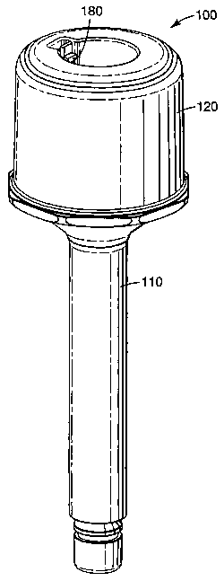
Figure 1 is a slightly elevated side view of a dosing device according to the
present
invention;
Figure 2 is vertical cross-section through a dosing device according to the
present
invention with the device in a first state;
Figure 2a is an enlarged vertical cross-sectional view taken from Figure 2, as
shown;
Figure 3 is a vertical cross-section through the dosing device of Figure 2,
with the
device in a second state; and
Figure 4 is a side exploded view of a dosing device according to the present
invention.
Description of the Invention
In one embodiment, the dosing device of the present invention accurately
dispenses a predetermined amount of a liquid when a push-button is actuated
with finger
pressure. The liquid flows from the dosing chamber by gravity, perhaps into a
container
where it can be diluted with water or another liquid. When the dosing chamber
is empty, a
user can reset the device, which permits the dosing chamber to be refilled.
The device can
be used to dispense various types of liquids including cleaning solutions,
medicines,
detergents, food products, mouthwash, and pharmaceuticals. These and other
features of
the present invention are described in greater detail below.
Figures 1 through 4 show one embodiment of a dosing device 100 according to
the
present invention. It includes a main chamber 105 formed by a body 110 and cap
120, and
a dosing chamber 115 within the lower portion of body 110. The main chamber
includes
an upper opening 125, and the dosing chamber includes a lower opening 135. Cap
120
can be permanently secured to body 110 by, for example, spin or ultrasonic
welding or an
adhesive, or removably secured by threads or an interlocking engagement
system. If the
device is intended to be a unitary, single use device, then the cap is
typically permanently
secured to body 110. This may be desirable when, for example, the material
held in the
device is harmful, and should not be touched during for example a refilling
operation. A
2
CA 02474803 2004-08-03
WO 03/067200 PCT/US02/39612
device of this type may be designed so that it cannot be readily refilled once
the liquid in
the main chamber has been dispensed, meaning that there is no readily
available way to
refill the main chamber with liquid. If the device is intended to be
refillable, then as noted
above the cap may be removably secured to the body by, for example, threads or
another
sealable connection that can readily be disassembled or otherwise changed to
permit
refilling.
A plunger or shuttle 130 fits within the body, and passes through the upper
opening
125 and the lower opening 135, as shown in Figure 2. In the illustrated
embodiment, the
uppermost portion of the shuttle does not project beyond the top surface of
cap 120, and
thus the device should not dispense the liquid when pressure is applied
inadvertently to the
top of the device. In the illustrated embodiment, the arrangement of the
components also
prevents a person from returning the shuttle to the first position by grasping
the top of the
shuttle, though that is not a required feature of the invention. This feature
may be useful
because it can decrease the incidence of repeated dosing, which can be
undesirable for
reasons previously described. Upper seal 140 and lower seal 150 prevent fluid
contained
in either the main chamber or the dosing chamber from escaping from the device
unintentionally, by sealing against the inner surfaces of body 110 and 120 in
the manner
shown. The particular arrangement of the seals and the surfaces against which
they seal
depends on the design of the device. Shoulder seal 160 is also provided, and
when the
device is in a first state with the shuttle in a first position, as shown in
Figure 2, it
preferably does not seal against another surface. In this condition, fluid can
move freely
between the main chamber and the dosing chamber, and thus the dosing chamber
can be
filled with fluid or any other material held in the main chamber.
Figure 3 illustrates a second state of the device in which the shuttle 130 is
in a
second position and a measured dose of fluid is dispensed through lower
opening 135.
Upper seal 140 continues to seal the upper opening. Shoulder seal 160 seals
against
shoulder 170 of the body, which prevents any additional fluid from flowing
from the main
chamber into the dosing chamber while the shuttle is in the second position.
When the
measured dose has been released from the device, the lower end of shuttle 130
can be
pressed back into its first position within the device (for example by
pressing it against a
hard surface), which returns the device to its first state so that the dosing
chamber may be
refilled. In another embodiment, the bottom of the device can be adapted so
that the
CA 02474803 2004-08-03
WO 03/067200 PCT/US02/39612
shuttle can only be returned to the first position when it is acted on by
another specially
adapted device, which then requires the user to remove the dosing device from
a bottle or
the like before activating it again. This adaptation may include providing an
expanding
end on the shuttle so that the end of the device must be inserted into a
customized
passageway (for example on a caddy or carrier) that compresses the end of the
shuttle so
that it can be returned to the first position. Because the main chamber may
hold several
doses of liquid, or even dozens or hundreds of doses, the device can dispense
several or
many measured doses sequentially before it must either be refilled or
discarded.
In the embodiment just described, the device includes a buffer, meaning that
there
is at least some distance through which the shuttle travels when no material
can flow from
the main chamber into the dosing chamber (or vice versa), and no material can
flow out of
the dosing chamber. This buffering system is advantageous for reasons that may
not be
self evident. In the absence of a buffering system, the tolerances of the
various
components must be very, very small because if they are not, there may be at
least one
position in the travel of the shuttle where material flows from the main
chamber into the
dosing chamber and flows out of the dosing chamber. This can empty the entire
device in
a single actuation, usually unintentionally, and the result would be at least
annoying, and
perhaps dangerous. Devices of the present invention that include this
buffering feature
may be referred to as "buffered" devices. Buffered devices thus more reliably
dispense a
single dose, and only a single dose, during each actuation.
A number of additional features of the present invention may also be used if
desired. One is the use of an optional volumetric spacer 200 that can be
placed within
dosing chamber 115 to reduce the volume of space available for fluid within
the dosing
chamber. Thus, for example, if the dosing chamber would otherwise hold 15 ml
of fluid,
but only 5 ml of fluid should be dispensed with each dose, a volumetric spacer
having a
volume of 10 ml can be placed within the dosing chamber so that the volume
available for
the fluid is only 5 ml. The volumetric spacer can be any appropriate size, and
in the
illustrated embodiment it has a passage through the middle of which a portion
of shuttle
can be received. The spacer shown utilizes a geometry that permits rapid
evacuation of
the material being dispensed and minimal residual material left behind to
ensure accurate
dosing, and minimal residue remaining in the chamber when resetting the dosing
chamber.
The size, shape, and composition of the main chamber, the dosing chamber, and
any
4
CA 02474803 2004-08-03
WO 03/067200 PCT/US02/39612
volumetric spacer can be adapted to accommodate the particular liquids to be
dispensed,
as can the other components of the device.
Although the shuttle is preferably unbiased, meaning that it is not urged
toward
either the first or the second position, in one embodiment the shuttle is
biased toward the
first position (preferably by a spring). Then, when the shuttle is in the
second position and
the user releases pressure on the top portion of the shuttle, the shuttle
returns to the first
position and the dosing chamber is refilled. This enables the user to dispense
an additional
dose immediately. It can be disadvantageous, however, because repeated dosing
is simple
and thus more likely.
Another useful feature is a locking mechanism associated with the shuttle, the
use
of which prevents the shuttle from being moved from the first position to the
second
position until it is released. One embodiment of such a locking mechanism is
shown in
Figures 2 and 2a, in which a spring-arm 180 is molded into cap 120, and is
biased toward
the shuttle. In its normal position, the spring-arm interferes with the
movement of the
shuttle, but when moved radially away from the shuttle (toward the left, in
Figures 2 and
2a), permits the shuttle to be moved toward the second position. This prevents
inadvertent
dispensation of material from the device, and in other embodiments with known
design
characteristics may qualify as a child-proof safety feature. Because of the
design of the
device, at least in the embodiment shown, material can be dispensed from the
device
without having a user's fingers near the point at which the material is
dispensed, which
results in a safer product. Stated another way, the activation location (where
the user
depresses the upper end of the shuttle, as shown at 225 in Figures 2 and 3) is
on the
opposite end of the device, and thus is spaced away from, the dispensation
location (where
material exits the dosing chamber). It should also be noted that the device of
the present
invention is self contained, or unitary, and is not necessary for it to be
screwed onto or
otherwise affixed to a standard spray or other bottle, as are other known
dispensing
systems.
The particular materials used in the manufacture of the components of the
present
invention may be selected to fit the application to which the device is
expected to be used.
One useful consideration is that the materials should be selected so that they
do not
degrade when exposed to the liquids expected to be dispensed by the device, or
by UV
light, the passage of time, or any other environmental factors. For example,
plastic and/or
CA 02474803 2004-08-03
WO 03/067200 PCT/US02/39612
metal may be used for the main chamber (body and cap), the dosing chamber, the
shuttle,
and the volumetric spacer components of the dosing device. Various seal
materials could
be used depending on the severity of the fluid, the precision of the processes
that make the
mating parts, and the friction required to overcome the seals in order to move
the shuttle
from position to position. One potentially suitable material for the seals is
an ethylene-
propylene O-ring available from Apple Rubber Products under the designation
AS56~-
014. Another type of seal believed to be useful with the device of the present
invention is
a U-cup seal, such as the ones available from C&C Packings, Inc. under the
designation
014 Bunya N70 U-cup 5. Cup seals may offer less resistance to sliding motion,
and may
be directional so that the proper orientation of the seal can be important.
Yet another type
of seal believed to be useful with the device of the present invention is a
quad ring seal,
such as the ones available from RT Enterprises under the designation Quattro
Seal 400-
014. Combinations of seal materials could also be used. In addition, sealing
can be
obtained by sizing the mating surface of the components with a slight
interference or with
slightly raised rings molded integral to the sliding member. The diameters of
the shaft
where the seals are located are preferably the same, so that the volume of the
dosing
chamber does not change when the device is activated. Also, because the upper
and lower
seals are in use much more than the middle seal, they may be designed using
superior
materials.
Other advantages of the dosing device of the present invention include the
fact that
it preferably does not include any type of motor or power source, that it can
safely be
inverted, dropped, rolled, or otherwise moved without spilling the liquid, and
that it does
not rely on methods of activation (such as squeezing a bottle or container)
that can be non-
uniform and therefore inaccurate.
The dosing device of the present invention may be shipped and sold either full
or
empty, and if sold while Rill, can be either refillable, or reuseable for so
long as there is
enough liquid in the main chamber to fill the dosing chamber. One way to
provide a
refillable dosing device is to thread the connection between the cap 120 and
the body 110,
so that the cap can be removed for refilling. The fluids used with the present
device are
preferably ones that readily flow due simply to gravitational forces, but
other more viscous
fluids could be dispensed with some modifications to the device. For example,
the shuttle
could pass further out of the lower opening of the device to permit easier
exit of liquid
6
CA 02474803 2004-08-03
WO 03/067200 PCT/US02/39612
from the device. Accordingly, although the present invention has been
described
primarily with reference to liquids, more viscous materials and even powders,
pastes, and
solid pellets may also be used if they flow sufficiently to enable them to
fill the dosing
chamber and subsequently exit the device. Fluids that may be used with the
device of this
invention include, but are not limited to, cleaning chemicals and
concentrates, protective
chemicals, detergents, food products, mouthwash, pharmaceuticals, food service
products,
animal care products, automotive materials, construction materials, adhesives,
and
personal hygiene materials such as hand creams and lotions.
Other optional features of the dosing device of the present invention include
the
following. The shape of the outside of the housing can be designed so that
only that
dosing device fits into a bottle having a complementary-shaped neck. This can
be done by
providing a key on one device and a keyway on the other, or by other known
methods.
This can be particularly useful for matching up a set of bottles with a set of
dosing
devices, so that they provide a comprehensive system. In another embodiment,
the lower-
most portion of the device could be slightly pointed, so that any drops of
liquid would
collect and then drip off that point instead of remaining on the bottom of the
device. In
another embodiment, some or all of the interior surfaces of the device could
be coated
with an appropriate coating to facilitate the draining of the contents of the
device.
The appropriate amount of concentrate or liquid can be determined by the
manufacturer or user. If, for example, the dosing device is sold or commonly
used with a
dispenser, such as a 0.95 liter (32 ounce) spray bottle, then the dose size
can be determined
by knowing the concentration of the liquid that, when diluted by another
liquid such as
water, will yield 0.95 liters (32 ounces) of liquid.
The dosing device of the present invention may be sold or used with a carrier
that
includes spaces for one or more dosing devices, one or more containers such as
spray
bottles, cleaning tools, and other supplies that may be used in connection
with the dosing
device.
The present invention has now been described with reference to several
embodiments thereof. It will be apparent to those skilled in the art that many
changes can
be made in the embodiments described without departing from the scope of the
present
invention. Not all of the portions of the overall design shown in, for
example, Figure 1 are
required. Thus the scope of the present invention should not be limited to the
structures
7
CA 02474803 2004-08-03
WO 03/067200 PCT/US02/39612
described in this application, but only by structures described by the
language of the
claims and the equivalents of those structures.