Note: Descriptions are shown in the official language in which they were submitted.
CA 02475291 2004-07-16
1
RECEPTACLE FOR INTERNAL FLAME GAS BURNER AND HOB COMPRISING A
RECEPTACLE OF THIS KIND AND A BURNER OF THIS KIND
BACKGROUND OF THE INVENTION
Field of the invention
The present invention relates to a receptacle far an internal flame gas
burner and a hob comprising a receptacle of this kind and a burner of this
kind.
Description of the prior art
Known in the art are internal flame gas burners, that is to say gas burners
having a central hollow portion usually called the "chimney" from which exit
flames
for heating vessels such as saucepans.
These burners, which are different from the standard peripheral flame gas
burners equipping conventional cookers, are generally appreciated for their
improved
energy performance: for the same quantity of gas supplied, the contents of a
vessel
are heated much faster.
Without this list claiming to be exhaustive, examples of internal flame gas
burners may be found in the following patents: FR 01 15643 (A.E.M.), FR 02
16041
(Gaz de France) and JP 10 19425 (RINNAf KK).
One particular object of the present invention is to provide means for further
improving the energy performance of internal flame gas burners.
SUMMARY OF THE INVENTION
The subject of the invention is achieved with an internal flame gas burner
receptacle comprising:
a) at least one sealed cup having at least one gas inlet orifice,
b) at least one cover provided with a central flame exit opening and
conformed to cover the cup, and
c) means for maintaining a calibrated space between the periphery of the
cover and the rim of the cup.
This receptacle in accordance with the invention encloses an internal flame
gas burner in a volume to which the entry of gas is totally controlled.
In particular the entry of air may be calibrated to optimize the process of
combustion taking place within the burner and thereby optimize the performance
of
the burner.
According to other features of the receptacle:
- the cover has a flame deflector shape;
CA 02475291 2004-07-16
2
- the cover has a frustoconical region with the opening at the bottom;
- the cover comprises vessel support lugs.
The present invention also provides a top plate comprising at least one
receptacle as defined hereinabove and a plate joined and sealed to the rim of
the
cup.
According to other features of the top plate, the opening is under the plate.
The present invention further provides a hob comprising a top plate as
defined hereinabove and at least one internal flame burner disposed in the
receptacle whose injector communicates with the gas inlet orifice and whose
chimney is disposed in line with the opening.
According to other features of the hob:
- the gas burner is of the compact type;
- the burner comprises an aspiration tube situated substantially in the plane
in which the flame outlet orifices of said burner discharge;
- it comprises a plurality of receptacles and burners of different sizes.
Other features and advantages of the present invention will become
apparent in the light of the following description and on examining the
appended
drawings.
BRIEF DESCRIPTION OF THE DRAWINGS
Figure 1 is an exploded perspective view of a hob according to the
invention.
Figure 2 is a perspective view of a top plate forming part of the figure 1
hob.
Figure 3 is an exploded perspective view of one of the burners of the figure
1 hob.
Figure 4 is a perspective view of one of the covers forming part of the figure
1 hob.
Figure 5 is a view in section in the plane P in figure 1 of a portion of the
hob
from that figure.
DETAILED DESCRIPTION OF THE PREFERRED EMBODIMENT
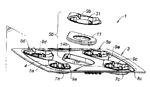
Refer now to figure 1, which represents a hob 1 according to the invention.
The hob 1 comprises a top plate 3 in turn comprising a plurality of
receptacles 5a to 5e connected to each other by a plate 4, each receptacle
comprising a cup 7a to 7c and a cover 9a to 9e.
Within each of the cups 7a to 7c is an internal flame burner 11; only one of
the burners may be seen in figure 1, in a position withdrawn from the hob, as
may its
CA 02475291 2004-07-16
3
associated cup 7b
Refer now to figure 2, which shows that the top plate 3 may be a metal plate
4 pressed to form a plurality of cups 7a to 7e each preferably having the
shape of a
slice of cake.
Alternately, the cups may be fabricated independently of each other and
attached, for example welded, to a metal plate 4 joining them together.
Each cup 7a to 7e has a gas inlet orifice 14a to 14c.
Refer next to figure 3, which is an exploded perspective view of an internal
flame burner 11 that may be used with the top plate 3 of the invention.
This burner conforms to the teaching of patent application FR 02 16041, but
it must be clearly understood that this example is in no way limiting on the
invention.
Briefly, this burner 11 comprises a gas injector 15, an aspiration tube 17, a
pot19,ahdacap21.
The function of the aspiration tube 17, also known as a "Venturi", is to draw
in primary combustion air, this induction or aspiration of air resulting from
a pressure
drop in the tube 17 caused by the gas leaving the injector 15 and being
accompanied by turbulence whereby the primary air is mixed with the gas.
The cap 21 caps the pot 19 and, with the pot 19, delimits an annular
chamber 23 whose internal edge 25 includes flame outlet orifices 27.
The air and the gas coming from the tube 17 finish up by mixing intimately in
this chamber 23, the resulting combustible mixture being divided homogeneously
and distributed to the flame outlet orifices 27, where it ignites and burns in
secondary
air from the surroundings.
The tube 17 extends along an axis that is substantially in the plane onto
which the orifices 27 discharge and preferably has a length at most twice the
radius
of the internal rim 25 of this chamber.
Because of this length to radius ratio, a burner of this kind is small in the
horizontal direction and may therefore be described as "compact".
A distribution member 29 in the shape of a circular arc is disposed between
the outlet of the tube 17 and those of the orifices 27 that face it.
Refer next to figure 4, which represents a cover 9 that may be used with the
top plate of the invention.
As may be seen in this figure, this cover 9 comprises a central flame exit
opening 31 which is at the bottom of a frustoconical portion 33 around which
are
distributed several vessel support lugs 35a to 35d, for example four such
lugs.
CA 02475291 2004-07-16
4
The general shape of the cover 9 corresponds to that of the cups 7a to 7d
(see figure 2).
All of the members just described may be fabricated from stainless steel or
a similar alloy.
Refer next to figure 5, which shows how a cup 7, an internal flame burner 11
and a cover 9 are arranged relative to each other in an operational situation.
The burner 11 represented in this figure has a slightly different shape from
that which has just been described; the invention is not limited to any
particular
design of internal flame burner.
Figure 5 shows that the aspiration tube 17 is disposed in line with the gas
injector 15, which is in turn disposed in the gas inlet orifice 14 of the cup
7.
The burner 11 is simply placed on the bottom of the cup 7.
A space E is formed between the periphery of the cover 9 and the plate 4,
enabling air A to circulate from the exterior toward the interior of the cup
7.
The space E is obtained by any appropriate means, such as spacers (not
shown) disposed between the cover 9 and the plate 4.
The chimney 37 of the burner 11, that is to say the region of the burner onto
which the flame outlet orifices 27 discharge, is disposed in line with the
central
opening 31 of the cover 9.
The central opening 31 is under the plate 4 of the top plate 3.
The rim 39 of the central opening is curved on itself so that it has a flame
deflector shape.
The mode of operation and the advantages of the invention follow directly
from the foregoing description.
Refer to figure 5 in particular.
The cover 9 and the cup 7 form a volume that is virtually closed on the
inside and into which the incoming flow of air A may be totally controlled.
In particular the space E may be calibrated so that the flow of air A
optimizes the energy efficiency of the burner 11, which utilizes a portion A1
of this air
as primary air (mixed directly with the gas arriving via the injector 15) and
another
portion A2 of this air as secondary air (incorporated into the combustion in
the area
of the chimney 37).
In this way the air A may be metered to reduce unburned particles in
particular.
The frustoconicai shape of the cover 9 lowers the bottom of the vessel to be
CA 02475291 2004-07-16
heated relative to the plate 4, which reduces vertical bulk and is
particularly
beneficial from an esthetic point of view.
In particular, the burners may be practically invisible from the outside,
which
yields a very restrained design.
5 An ultra flat hob may be obtained by using an internal flame burner like
that
represented in the figures, that is to say of the type having an aspiration
tube 17
substantially in the plane in which the flame outlet orifices 27 discharge.
The curved shape of the rim 39 of the opening 31 encourages the
distribution of the flames under the vessel to be heated: thanks to this
shape, the
flames are first directed toward the center of the chimney 37 and then curved
upward
and toward the exterior of the burner.
The covers 9a to 9e further protect the burners and the cups from soiling by
the contents of the vessels to be heated.
Taking all of the air necessary for combustion from above the cooking
surface conforms to the applicable standards.
Sealing the connection of the cups 7a to 7e to the plate 4 prevents any
accidental confinement of gas under the cooking surface.
Of course, the present invention is not limited to the embodiment described
and shown.
For example, the hob of the invention could be limited to a top plate
comprising only one cup and one burner.
Likewise the hob of the invention could comprise a "collective" cup andlor
cover, that is to say one receiving or covering a respective plurality of
burners.