Language selection

Search

Patent 2475344 Summary

Third-party information liability

Some of the information on this Web page has been provided by external sources. The Government of Canada is not responsible for the accuracy, reliability or currency of the information supplied by external sources. Users wishing to rely upon this information should consult directly with the source of the information. Content provided by external sources is not subject to official languages, privacy and accessibility requirements.

Claims and Abstract availability

Any discrepancies in the text and image of the Claims and Abstract are due to differing posting times. Text of the Claims and Abstract are posted:

  • At the time the application is open to public inspection;
  • At the time of issue of the patent (grant).
(12) Patent Application: (11) CA 2475344
(54) English Title: FLASHLIGHT FOR A POWER TOOL
(54) French Title: LAMPE DE POCHE POUR OUTIL ELECTRIQUE
Status: Deemed Abandoned and Beyond the Period of Reinstatement - Pending Response to Notice of Disregarded Communication
Bibliographic Data
(51) International Patent Classification (IPC):
  • F21V 33/00 (2006.01)
  • B25F 05/00 (2006.01)
  • F21L 04/00 (2006.01)
(72) Inventors :
  • SMITH, BROCK A. (Canada)
  • TREMBLAY, DARRYL (Canada)
(73) Owners :
  • BROCK A. SMITH
  • DARRYL TREMBLAY
(71) Applicants :
  • BROCK A. SMITH (Canada)
  • DARRYL TREMBLAY (Canada)
(74) Agent:
(74) Associate agent:
(45) Issued:
(22) Filed Date: 2004-07-20
(41) Open to Public Inspection: 2006-01-20
Availability of licence: N/A
Dedicated to the Public: N/A
(25) Language of filing: English

Patent Cooperation Treaty (PCT): No

(30) Application Priority Data: None

Abstracts

English Abstract


The flashlight is used in conjunction with a hand-held power drill assembly
and includes a
battery housing having a light bulb and on off switch. A strap is attached to
the battery housing
and is adapted to encircle a portion of the drill housing adjacent to its
chuck. A, fastener removably
attaches the strap to the drill housing and facilitates the attachment of the
flashlight to a wide
variety of locations on the drill housing where the flashlight will provide
maximum illumination for
a given job.


Claims

Note: Claims are shown in the official language in which they were submitted.

We claim:
1. A removable flashlight for use in conjunction with a power tool assembly,
said flashlight
including: a housing having a light bulb; a battery mounted within said
housing and electrically
connected to said light bulb; switch means for activating and deactivating
said light bulb; a strap
attached to said housing; and a fastener associated with said strap for
removably attaching said
strap to said power tool assembly.
2. A removable flashlight for use in conjunction with a hand-held power drill
assembly
having a drill housing, an electric motor mounted within said housing; a chuck
mounted for
rotation to said housing and to which said drill is attached, said .flashlight
including: a battery
housing having a light bulb mounted thereto; a battery mounted within said
battery housing and
electrically connected to said light bulb; switch means for activating and
deactivating said light
bulb; a strap attached to said battery housing and adapted to encircle a
portion of said drill
housing adjacent to said chuck; and a fastener associated with said strap for
removably attaching
said strap to said drill housing.
3. The flashlight of claims 1 or 2 wherein the effective length of said strap
is adjustable.
4. The flashlight of claims 1 or 2 wherein said strap is slidingly attached to
said battery
housing.
5. The flashlight of claims 1 or 2 wherein said fastener is Velcro
6. In combination, a power tool assembly and a removable light source, said
light source
5

including: a housing having a light bulb; a battery mounted within said
housing and electrically
connected to said light bulb; switch means far activating and deactivating
said light bulb; a strap
attached to said housing; and a fastener associated with said strap for
removably attaching said
strap to said power tool assembly.
7. In combination, a hand-held power drill assembly and a removable light
source, said
power drill assembly having a drill housing, an electric motor mounted within
said housing; a
chuck mounted for rotation to said housing and to which said drill is
attached, said flashlight
including: a battery housing having a light bulb mounted thereto; a battery
mounted within said
housing and electrically connected to said light bulb; switch means for
activating and
deactivating said light bulb; a strap attached to said battery housing and
adapted to encircle a
portion of said drill housing adjacent to said chuck; and a fastener
associated with said strap for
removably attaching said strap to said drill housing.
8. The flashlight of claims 6 or 7 wherein the effective length of said strap
is adjustable.
9. The flashlight of claims 6 or 7 wherein said strap is slidingly attached to
said battery
housing.
10. The flashlight of claims 6 or 7 wherein said fastener is Velcro.
6

Description

Note: Descriptions are shown in the official language in which they were submitted.


CA 02475344 2004-07-20
FIELD OF THE INVENTION
This invention relates to light sources for illuminating work-areas and more
particularly
to a source of light or flashlight attached to a battery-powered tool assembly
for illuminating the
area where the tool is being used.
BACKGROUND OF THE INVENTION
Tools that are powered by batteries such as power drills and power screw
drivers have
many advantages over power tools that must be plugged in. Among those
advantages are: first,
battery-powered tools can be used on job-sites which lack electrical outlets,
secondly such tools
can accomplish more work in a given period of time since no time is spent in
carrying an
electrical cable and in searching for an electrical outlet to plug the cable
into. A third advantage
is that, battery-powered tools are generally lighter and easier to carry than
plug-in tools.
An additional advantage of battery-powered tools is that they are useful where
the work-
areas are inaccessible whereas tools that must be plugged-in frequently are
not. However a
problem that is often encountered when working in inaccessible work-areas is
poor lighting.
Work-areas such as stair wells, spaces above drop ceilings, spaces between
lower sub-floors and
upper finished floors are often poorly lit or entirely devoid of light. Steps
must be taken to
illuminate those areas before any work can be carried out in them.
Patents are known which describe light sources for use in conjunction with
battery-
powered tools. An example of such patents is no. U. S. patent no. 5,169,225 to
Palm. The source

CA 02475344 2004-07-20
of light described in this patent is mounted beneath the handle of the
assembly and the light is
directed ahead of the assembly. The light source, being at the bottom of the
assembly, is
frequently not close enough to the tool, which is at the top of the assembly,
to effectively
illuminate the area where the tool is operating. If the tool is operating in a
confined area such as a
slot, a box, or a corner, the flashlight may not adequately illuminate the
work-area.
We have invented a flashlight that can be used in conjunction with a
conventional
battery-powered tool assembly. The flashlight is not permanently attached to
the assembly but
may be attached and detached from it. The flashlight can be attached at a
location on the tool
assembly where it will provide maximum illumination for any given job. If for
example, the tool
is a drill, and the tool is being used to drill a hole in a box, the
flashlight can be placed adjacent
to the chuck that holds the drill so that it directs light directly into the
box. If a hole is being
drilled into a corner, the flashlight can be placed below the handle so that
it directs light
upwardly into the corner.
SUMMARY OF THE INVENTION
Briefly, the removable flashlight of our invention includes a housing having a
light bulb;
a battery mounted within the housing and electrically connected to the light
bulb and switch
means for activating and deactivating the light bulb. A strap is attached to
the housing and a
fastener is associated with the strap for removably attaching the strap to a
power tool assembly.
2

CA 02475344 2004-07-20
DESCRIPTION OF THE DRAWING
The removable flashlight of our invention is described with reference to the
accom-
panying drawing in which:
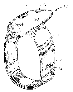
Figure 1 is a perspective view of the flashlight; and
Figure 2 is a perspective view of the flashlight, in smaller scale, in
conjunction with a
power tool assembly.
Like reference characters refer to like parts throughout the description of
the drawing.
DESCRIPTION OF PREFERRED EMBODIMENT
With reference to Figure l, the flashlight of the invention, generally 10, has
a housing 12,
an electric light bulb 14 at one end of the housing and a switch 16 at the top
of the housing. The
switch is electrically connected to the light bulb and the battery for turning
the bulb on and off in
the usual manner.
A strap 18 passes through a slot 20 adjacent to the bottom of the housing.
Strips 22, 24 of
nylon fabric are attached to the strap adjacent to its ends. One strip is
looped while the other is
burred and the two strips adhere to each other when pressed together.
Together, the strips make
up a fastener identified by the trade-mark VELCRO.
With reference to Figure 2, the strap 18 of the flashlight encircles the
housing of a port-
able hand-held drill assembly 30. The assembly has a housing comprising a
handle 32 and a
compartment 34. An electric motor (not visible) is mounted within the
compartment and a chuck
3

' CA 02475344 2004-07-20
36 is mounted for rotation at the front of the compartment. A drill 38 is
rernovably connected to
the chuck in the usual manner. A trigger 40 is mounted to the handle and
causes the chuck to
rotate.
By means of the VELCRO fastener, the effective length of strap 18 can be
adjusted so
that the flashlight can be attached to the housing adjacent to the chuck, to
the handle 36 or
elsewhere on the drill assembly.
It will be understood, of course, that modifications can be made in the
structure of the
flashlight of the invention without departing from the scope and purview of
the invention as
defined in the appended claims.
4

Representative Drawing
A single figure which represents the drawing illustrating the invention.
Administrative Status

2024-08-01:As part of the Next Generation Patents (NGP) transition, the Canadian Patents Database (CPD) now contains a more detailed Event History, which replicates the Event Log of our new back-office solution.

Please note that "Inactive:" events refers to events no longer in use in our new back-office solution.

For a clearer understanding of the status of the application/patent presented on this page, the site Disclaimer , as well as the definitions for Patent , Event History , Maintenance Fee  and Payment History  should be consulted.

Event History

Description Date
Revocation of Agent Requirements Determined Compliant 2020-09-01
Application Not Reinstated by Deadline 2007-07-20
Time Limit for Reversal Expired 2007-07-20
Deemed Abandoned - Failure to Respond to Maintenance Fee Notice 2006-07-20
Application Published (Open to Public Inspection) 2006-01-20
Inactive: Cover page published 2006-01-19
Inactive: Correspondence - Formalities 2005-08-03
Inactive: First IPC assigned 2004-10-07
Inactive: IPC assigned 2004-10-07
Application Received - Regular National 2004-09-02
Inactive: Filing certificate - No RFE (English) 2004-09-02

Abandonment History

Abandonment Date Reason Reinstatement Date
2006-07-20

Fee History

Fee Type Anniversary Year Due Date Paid Date
Application fee - small 2004-07-20
Owners on Record

Note: Records showing the ownership history in alphabetical order.

Current Owners on Record
BROCK A. SMITH
DARRYL TREMBLAY
Past Owners on Record
None
Past Owners that do not appear in the "Owners on Record" listing will appear in other documentation within the application.
Documents

To view selected files, please enter reCAPTCHA code :


To view images, click a link in the Document Description column. To download the documents, select one or more checkboxes in the first column and then click the "Download Selected in PDF format (Zip Archive)" or the "Download Selected as Single PDF" button.

List of published and non-published patent-specific documents on the CPD .

If you have any difficulty accessing content, you can call the Client Service Centre at 1-866-997-1936 or send them an e-mail at CIPO Client Service Centre.


Document
Description 
Date
(yyyy-mm-dd) 
Number of pages   Size of Image (KB) 
Claims 2004-07-19 2 79
Description 2004-07-19 4 143
Drawings 2004-07-19 1 39
Abstract 2005-08-02 1 14
Representative drawing 2005-12-27 1 15
Filing Certificate (English) 2004-09-01 1 167
Reminder of maintenance fee due 2006-03-20 1 112
Courtesy - Abandonment Letter (Maintenance Fee) 2006-09-13 1 175
Correspondence 2004-09-01 1 14
Correspondence 2005-08-02 2 40