Language selection

Search

Patent 2475636 Summary

Third-party information liability

Some of the information on this Web page has been provided by external sources. The Government of Canada is not responsible for the accuracy, reliability or currency of the information supplied by external sources. Users wishing to rely upon this information should consult directly with the source of the information. Content provided by external sources is not subject to official languages, privacy and accessibility requirements.

Claims and Abstract availability

Any discrepancies in the text and image of the Claims and Abstract are due to differing posting times. Text of the Claims and Abstract are posted:

  • At the time the application is open to public inspection;
  • At the time of issue of the patent (grant).
(12) Patent Application: (11) CA 2475636
(54) English Title: DEVICE FOR EXTERNALLY IMMOBILIZING BROKEN BONES
(54) French Title: DISPOSITIF DE FIXATION EXTERNE D'OS CASSES
Status: Deemed Abandoned and Beyond the Period of Reinstatement - Pending Response to Notice of Disregarded Communication
Bibliographic Data
(51) International Patent Classification (IPC):
  • A61B 17/64 (2006.01)
  • A61B 17/86 (2006.01)
(72) Inventors :
  • WERDING, GERD (Germany)
  • SCHNEIDER, WILLI (Germany)
(73) Owners :
  • GERD WERDING
  • WILLI SCHNEIDER
(71) Applicants :
  • GERD WERDING (Germany)
  • WILLI SCHNEIDER (Germany)
(74) Agent: BLAKE, CASSELS & GRAYDON LLP
(74) Associate agent:
(45) Issued:
(86) PCT Filing Date: 2003-02-10
(87) Open to Public Inspection: 2003-08-21
Availability of licence: N/A
Dedicated to the Public: N/A
(25) Language of filing: English

Patent Cooperation Treaty (PCT): Yes
(86) PCT Filing Number: PCT/EP2003/001293
(87) International Publication Number: EP2003001293
(85) National Entry: 2004-08-11

(30) Application Priority Data:
Application No. Country/Territory Date
202 02 049.5 (Germany) 2002-02-11

Abstracts

English Abstract


The invention relates to a device for externally immobilizing broken bones,
particularly bones of the extremities. According to the invention, the device
has a multi-articulation rod that can be placed on the outside of the body
while extending along a broken bone. This rod comprises elements (1), which
can move in relation to one another and can be fixed in appointed directions.
One of the elements (1) has a bone pin (7), which can be held therein in a
manner that permits it to turn and which is provided for being anchored inside
the bone. In addition, the tip of at least one of the bone pins (7) is
provided in the form of a screw having a self-tapping thread (8).


French Abstract

L'invention concerne un dispositif de fixation externe d'os cass~s, en particulier d'os des extr~mit~s. Ce dispositif pr~sente une tige pluriarticul~e, pouvant Útre install~e ~ l'ext~rieur du corps le long d'un os cass~. Cette tige est constitu~e d'~l~ments (1), pouvant Útre orient~s les uns par rapport aux autres et fix~s dans les orientations r~gl~es. Une partie de ces ~l~ments (1) pr~sente une broche (7) ~ ancrer dans un os, maintenue dans cette partie de fa×on ~ pouvoir tourner autour d'un axe, et au moins une des broches (7) est con×ue, au niveau de sa pointe, sous la forme d'une vis autotaraudeuse (8).

Claims

Note: Claims are shown in the official language in which they were submitted.

4
Claims
1. A device for externally immobilizing broken bones, particularly bones of
the extremities,
comprising a multi-articulation rod that can be placed on the outside of the
body while extending
along a broken bone, said rod comprising elements (1) which can move in
relation to one another
and can be fixed in desired directions with respect to one another, one of the
elements (1) having
a bone pin (7) which can be held therein in a manner that permits it to turn
and which has means
for being anchored inside the bone, characterized in that the tip of at least
one of the bone pins
(7) is in the form of a screw having a self-tapping thread (8).
2. A device as claimed in Claim 1, characterized in that said bone pin (7) is
screwably
guided in the element (1) associated with it by a self-locking thread (10),
the thread pitch of the
thread at the tip of the bone pin being approximately the same as that of the
self locking thread.
3. A device as claimed in Claim 2, characterized in that, for inserting the
shaft of the
bone pin into element (1) a housed knurled nut (9) is provided that is
accessible to the hand and
can be turned in the element but cannot be moved axially out of place with
respect to element (1)
the self-locking thread (10) of the bone pin (7) engaging and being held by
the knurled nut.

Description

Note: Descriptions are shown in the official language in which they were submitted.


CA 02475636 2004-08-11
WO 03/068084 PCTEP03/01293
Device for Externally Immobilizing of Broken Bones
Description
The invention concerns a device of the type referred to in the preamble to
claim 1 for
externally immobilizing broken bones.
DE 19746687 A1 discloses a device of this type. The bone pins of the known
device
feature smooth tips, whereby the pins held in the elements and turnable in
them are embedded
into the bones using a small electric drill, and under particular hand-applied
pressure. The
embedded bone pin is then fixed to the element of the device to which it
belongs by means of a
counternut tightened against the element.
The disadvantage of the known device is that embedding the bone pin involves
relatively
high equipment use, because in the process of being secured the bone pin must
be embedded
relatively deeply into the bone because of the smoothness of its tip, and
because the use of the
electric drill for the purpose of embedding the pin causes unnecessary stress
to the bone through
the high rotational speed that is used and also required in this procedure.
Therefore the challenge of this invention is to improve a device of the type
mentioned
above in such a way that the bone pin can be anchored securely with the least
possible stress to
the bone.
According to the invention this challenge is solved through a device for
externally
immobilizing broken bones with the distihguishing features of Claim 1.
The achievement resulting from the bone pin of this design will be that, using
a tool such
as a spanner or screwdriver, the pin can be screwed into the bone, and that it
will in this manner
become anchored in a way similar to that of a corkscrew being screwed into a
cork. Depths of
penetration that are substantially lower than those used for known bone pins
will be adequate for
securely anchoring the bone pins to the bones.
40210273.3

CA 02475636 2004-08-11
WO 03/068084 PCTEP03l01293
2
The preferred embodiment of the invention in accordance with Claim 2 achieves
the
result that the screwed in bone pin remains in its screwed in position,
thereby preventing it from
unscrewing itself loose from the bone independently.
In the preferred embodiment of the invention in accordance with Claim 3, it is
possible to
adjust the height of the device's element holding the bone pin in relation to
the bone once the pin
has been screwed in.
A preferred embodiment of the invention is described as illustrated in the
attached
drawings. In these:
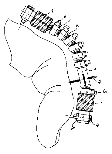
Fig. 1 illustrates a device for externally immobilizing bones used on a finger
according to
the invention, and
Fig. 2 (a) - (d) illustrates an element of the device which holds a bone pin
that can be
screwed into the bone. The element is shown in a side view, rear view, from
above and in
perspective.
As can be seen from Fig. l, the immobilization device features a chain of
elements 1
which, as can be seen more clearly in Fig. 2, are joined to one another in
ball joint fashion. Each
element features a ball on one end and a ball socket 3 on the other, whereby
each ball 2 of one
element is contained by ball socket 3 of the adjacent element. The relative
position of the
elements that are joined in this manner in a ball and socket style is
established by the clamps 6
that enclose the ball socket, pressing together ball sockets 3 that have been
given elastic
deformation capabilities by the provision of slits 11, against the balls 2
which they hold.
At the ends of the immobilization device there are conventional type bone pins
that can be
grasped at the head 4 with an electric drill by way of example. After having
been inserted into
the bone, the bone pin can be screwed tight against the element in which it is
located with a
counternut.
40210273.3

CA 02475636 2004-08-11
WO 03/068084 PCTEP03/01293
3
Bone pin 7, in accordance with the invention, is situated in an element
located between the ends.
This constitutes a screw featuring a tip having a self tapping thread 8,
similar to a self tapping
screw or a corkscrew. When it is screwed in, the bone pin becomes anchored to
the bone. In this
way stability is achieved at a smaller penetration depth than is the case with
conventional bone
pins, as illustrated at the ends of the immobilization device.
Bone pin 7 is fixed to element 1 through a knurled nut 9 that is housed in
such a way that
it can be turned but cannot be displaced axially. The bone pin 7 engages
together with the
knuled nut 9 by means of a self locking thread 10. If the knurled nut 9, which
is accessible from
the outside (insofar as it is needed), is held with the hand and the screw is
turned at the head,
either using a tool or by hand, then the bone pin 7 moves in the bone. The
thread pitch of the
self locking thread 10 approximately corresponds to that of the self threading
thread 8. The
result achieved by the self locking action is that the bone pin 7 is safe
against unwanted turning
without need for any further measures.
If, after it has been screwed into the bone, the bone pin 7 is held, and the
knurled nut 9 is
turned, then the height of the element holding bone pin 7 can be changed in
relationship to the
bone. The thread's self locking nature also ensures that once the position has
been established, it
will not change by itself.
In the illustrated embodiment only the bone pin situated in the middle has
been developed
in accordance with the invention, while the bone pins at either end are of the
conventional type.
It is also possible, of course, to provide all bone pins of the same type as
the middle bone pin
illustrated in Fig. 1.
40210273.3

Representative Drawing
A single figure which represents the drawing illustrating the invention.
Administrative Status

2024-08-01:As part of the Next Generation Patents (NGP) transition, the Canadian Patents Database (CPD) now contains a more detailed Event History, which replicates the Event Log of our new back-office solution.

Please note that "Inactive:" events refers to events no longer in use in our new back-office solution.

For a clearer understanding of the status of the application/patent presented on this page, the site Disclaimer , as well as the definitions for Patent , Event History , Maintenance Fee  and Payment History  should be consulted.

Event History

Description Date
Inactive: Adhoc Request Documented 2013-12-10
Application Not Reinstated by Deadline 2009-02-10
Time Limit for Reversal Expired 2009-02-10
Inactive: Abandon-RFE+Late fee unpaid-Correspondence sent 2008-02-11
Deemed Abandoned - Failure to Respond to Maintenance Fee Notice 2008-02-11
Inactive: IPC from MCD 2006-03-12
Inactive: Cover page published 2004-10-14
Inactive: Notice - National entry - No RFE 2004-10-12
Inactive: Inventor deleted 2004-10-12
Application Received - PCT 2004-09-07
National Entry Requirements Determined Compliant 2004-08-11
Application Published (Open to Public Inspection) 2003-08-21

Abandonment History

Abandonment Date Reason Reinstatement Date
2008-02-11

Maintenance Fee

The last payment was received on 2007-02-07

Note : If the full payment has not been received on or before the date indicated, a further fee may be required which may be one of the following

  • the reinstatement fee;
  • the late payment fee; or
  • additional fee to reverse deemed expiry.

Patent fees are adjusted on the 1st of January every year. The amounts above are the current amounts if received by December 31 of the current year.
Please refer to the CIPO Patent Fees web page to see all current fee amounts.

Fee History

Fee Type Anniversary Year Due Date Paid Date
MF (application, 2nd anniv.) - standard 02 2005-02-10 2004-08-11
Basic national fee - standard 2004-08-11
MF (application, 3rd anniv.) - standard 03 2006-02-10 2006-02-07
MF (application, 4th anniv.) - standard 04 2007-02-12 2007-02-07
Owners on Record

Note: Records showing the ownership history in alphabetical order.

Current Owners on Record
GERD WERDING
WILLI SCHNEIDER
Past Owners on Record
None
Past Owners that do not appear in the "Owners on Record" listing will appear in other documentation within the application.
Documents

To view selected files, please enter reCAPTCHA code :


To view images, click a link in the Document Description column. To download the documents, select one or more checkboxes in the first column and then click the "Download Selected in PDF format (Zip Archive)" or the "Download Selected as Single PDF" button.

List of published and non-published patent-specific documents on the CPD .

If you have any difficulty accessing content, you can call the Client Service Centre at 1-866-997-1936 or send them an e-mail at CIPO Client Service Centre.


Document
Description 
Date
(yyyy-mm-dd) 
Number of pages   Size of Image (KB) 
Representative drawing 2004-08-10 1 15
Description 2004-08-10 3 129
Abstract 2004-08-10 2 80
Drawings 2004-08-10 2 40
Claims 2004-08-10 1 31
Notice of National Entry 2004-10-11 1 201
Reminder - Request for Examination 2007-10-10 1 127
Courtesy - Abandonment Letter (Maintenance Fee) 2008-04-06 1 175
Courtesy - Abandonment Letter (Request for Examination) 2008-05-04 1 167
PCT 2004-08-10 6 185
Fees 2006-02-06 1 30
Fees 2007-02-06 1 33