Language selection

Search

Patent 2475645 Summary

Third-party information liability

Some of the information on this Web page has been provided by external sources. The Government of Canada is not responsible for the accuracy, reliability or currency of the information supplied by external sources. Users wishing to rely upon this information should consult directly with the source of the information. Content provided by external sources is not subject to official languages, privacy and accessibility requirements.

Claims and Abstract availability

Any discrepancies in the text and image of the Claims and Abstract are due to differing posting times. Text of the Claims and Abstract are posted:

  • At the time the application is open to public inspection;
  • At the time of issue of the patent (grant).
(12) Patent Application: (11) CA 2475645
(54) English Title: HIGH FREQUENCY RIGHT ANGLE CONNECTOR
(54) French Title: CONNECTEUR HAUTE FREQUENCE A ANGLE DROIT
Status: Deemed Abandoned and Beyond the Period of Reinstatement - Pending Response to Notice of Disregarded Communication
Bibliographic Data
(51) International Patent Classification (IPC):
  • H01R 13/646 (2011.01)
  • H01R 24/70 (2011.01)
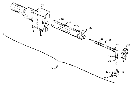
(72) Inventors :
  • SWANTNER, MICHAEL J. (United States of America)
  • BROWN, SHANE (United States of America)
  • SHERRY, JOHN (United States of America)
(73) Owners :
  • OSRAM SYLVANIA INC.
(71) Applicants :
  • OSRAM SYLVANIA INC. (United States of America)
(74) Agent: SMART & BIGGAR LP
(74) Associate agent:
(45) Issued:
(22) Filed Date: 2004-07-21
(41) Open to Public Inspection: 2005-03-17
Availability of licence: N/A
Dedicated to the Public: N/A
(25) Language of filing: English

Patent Cooperation Treaty (PCT): No

(30) Application Priority Data:
Application No. Country/Territory Date
10/737,303 (United States of America) 2003-12-16
60/503,619 (United States of America) 2003-09-17

Abstracts

English Abstract


A high frequency, right angle socket (10) comprising a body (12) including a
longitudinal
bore (14) extending completely through the body (12) and a transverse bore
(16) intersecting
the longitudinal bore (14). The bores (14) and (16) are seen most clearly in
Fig. 5. A first
dielectric (18) is formed to fractionally engage the longitudinal bore (14).
The dielectric (18)
has a proximal end (20) and a distal end (22) and includes a longitudinal
electric
contact-receiving chamber (24). A right angle electrical contact (26) has a
longitudinal portion (28)
and a transverse portion (30). The longitudinal portion (28) includes a first
contact retainer
(32). The transverse portion (30) includes a contact retainer (33). The
longitudinal portion
(28) is fitted into the longitudinal electrical contact-receiving chamber (24)
of the first
dielectric (18) with the contact retainer (32) on the longitudinal portion
(28) engaging the
interior wall of the longitudinal contact-receiving chamber (24). A second
dielectric (34) is
formed to fractionally engage the transverse bore (16) and includes a
transverse electrical
contact-receiving chamber (36). The transverse portion (30) of the right angle
electrical
contact (26) is fitted into the transverse electrical contact-receiving
chamber (36) with the
contact retainer (33) on the transverse portion (30) engaging the interior
wall of the
transverse electrical contact-receiving chamber (36). A cap (38) closes one
end of the
longitudinal bore (14).


Claims

Note: Claims are shown in the official language in which they were submitted.

Page 7
CLAIMS:
What is claimed is:
1. ~A high frequency, right angle socket comprising:
a body including a longitudinal bore extending completely through said body
and a
transverse bore intersecting said longitudinal bore;
a first dielectric formed to frictionally engage said longitudinal bore, said
dielectric
having a proximal end and a distal. end and including a longitudinal electric
contact receiving
chamber;
a right angle electrical contact having a longitudinal portion and a
transverse portion,
said longitudinal portion including a first contact retainer, said transverse
portion including a
second contact retainer, said longitudinal portion fitted into said
longitudinal electrical
contact receiving chamber of said first dielectric, said contact retainer on
said longitudinal
portion engaging the interior wall of said longitudinal contact receiving
chamber;
a second dielectric formed to frictionally engage said transverse bore and
including a
transverse electrical contact receiving chamber, said transverse portion of
said right angle
electrical contact fitted into said transverse electrical contact receiving
chamber; said contact
retainer on said transverse portion engaging the interior wall of said
transverse electrical
receiving chamber; and
a cap closing one end of said longitudinal bore.
2. ~The high frequency, right angle socket of Claim 1 wherein said distal end
of said first
dielectric includes an external shoulder that engages an internal shoulder
formed in said
longitudinal bore.

Page 8
3. The high frequency, right angle socket of Claim 2 wherein said second
dielectric
includes a chamfered end.
4. The high frequency, right angle socket of Claim 3 wherein said chamfered
end of said
second dielectric engages a chamfered edged at the terminus of said transverse
bore.
5. The high frequency, right angle socket of Claim 4 wherein said distal end
of said first
dielectric further includes an alignment slot and said second dielectric
includes an alignment
tab in engagement with said alignment slot.
6. The high frequency, right angle socket of Claim 5 wherein said proximal end
of said
first dielectric is cup-shaped for a given depth.
7. The high frequency, right angle socket of Claim 6 wherein said given depth
is less
than the length of said first dielectric.
8. The high frequency, right angle socket of Claim 7 wherein said body is
formed of
electrically conductive material; said cap is formed of electrically
conductive material and
said cap is held in position by coining.

Description

Note: Descriptions are shown in the official language in which they were submitted.


CA 02475645 2004-07-21
i
Attorney Docket No.: 03-2-319
Page 2
HIGH FREQUENCY RIGHT ANGLE CONNECTOR
003. TECHNICAL FIELD
004. This invention relates to electrical connectors and more particularly to
high
frequency right angle connectors.
005. BACKGROUND ART
006. High frequency right angle connectors C, shown in Figs. 1 and 2, are
known and a
previous type was composed of a die cast body 100, three Teflon~ screw machine
dielectrics, 102, 104 and 106, a contact 108 and a die cast cap 110. The
contact 108
was press-fitted into one of the dielectrics 102 to form a sub-assembly, which
was
then inserted into the die cast body 100. A second dielectric 104 was then
placed over
the corner of the contact 108. The third dielectric 106 was then placed over
the short
end of the contact 108 and pressed into an opening in the die cast body 100.
The die
cast cap 110 was then seated into the body 100 to complete the assembly.
007. This structure does not provide adequate shielding because of the gap 120
that
exists at the bend of the contact 108. The gap extends completely around the
bend.
Also, the short dielectric I06 has no stop feature to prevent it fi.°om
being pushed too
far into the die cast body. Therefore, the true position of the contact 108
was
determined by the fit of the pin into the dielectric and the associated
tolerances of
each component. These conditions proved unacceptable for the use of the
connector.
008. DISCLOSURE OF INVENTION
. ... ~ r! .~.. . ri. _rx x 4.. r _, _ ,. n v.#... .. ~._~___ . ._~. ~.-.. ~
,wp~"~,~,~,~~,~~,~~~~", ,~. w .r m..~__~____ _ __

CA 02475645 2004-07-21
Attorney Docket No.: 03-2-319
Page 3
009. It is, therefore, an object of the invention to obviate the disadvantages
of the prior
art.
0010. It is another object of the invention to enhance high frequency right
angle
connectors.
0011. It is another object of the invention to reduce the number of parts
necessary for
the connector.
IO 0012. These objects are accomplished, in one aspect of the invention, by
the provision
of a high frequency, right angle socket comprising a body including a
longitudinal
bore extending completely through the body and a transverse bore intersecting
the
longitudinal bore. A first dielectric is formed to frictionally engage the
longitudinal
bore, the dielectric having a proximal end and a distal end and including a
longitudinal electric contact-receiving chamber. A right angle electrical
contact has a
longitudinal portion and a transverse portion, the longitudinal portion
including a first
contact retainer. The transverse portion has a second contact retainer. The
longitudinal portion is fitted into the longitudinal electrical contact-
receiving chamber
of the first dielectric with the contact retainer on the longitudinal portion
engaging the
:~0 interior wall of the longitudinal contact-receiving chamber. A second
dielectric is
formed to frictionally engage the transverse bore and includes a transverse
electrical
contact-receiving chamber. The transverse portion of the right angle
electrical
contact is fitted into the transverse electrical contact-receiving chamber
with the
contact retainer on the transverse portion engaging the interior v~rall of the
transverse
electrical receiving chamber. A cap closes one end of the longitudinal bore.
0013. This construction provides fewer components and make s easier the
correct
positioning of the contact pin for both its mating end (the long portion) and
the circuit
board end (the short end). Shielding is effected by completely eliminating the
gap
___ .__w..~ ..~..,~~~,.~~..~._~~.n~.o~,~#~...~;r,:~.N,~~p~ y~..M H ..v...._
.___ .. . _. .__

CA 02475645 2004-07-21
Attorney Docket No.: 03-2-319
Page 4
around the bend of the contact pin. The cap is coined into place thus ensuring
that it
will remain in place during a soldering process.
0014. BRIEF DESCRIPTION OF THE DRAWINGS
00I 5. Fig. 1 is an exploded perspective view of a prior art connector;
0016. Fig. 2 is a longitudinal sectional view of the connector of Fig. 1;
0017. Fig. 3 is an exploded perspective view of an embodiment of the
invention;
0018. Fig. 4 is a longitudinal sectional view of the connector of Fig. 3; and
0019. Fig. 5 is a longitudinal sectional view of the connector body alone.
IS
0020. BEST MODE FOR CARRYING OUT THE INVENTION
0021. For a better understanding of the present invention, together with other
and
further objects, advantages and capabilities thereof, reference is made to the
following disclosure and appended claims in conjunction with the above-
described
drawings.
0022. Referring now to the invention with greater particularity, there is
shown in Figs. 3
and 4 a high frequency, right angle socket 10 comprising a t>ody 12 including
a
longitudinal bore 14 extending completely through the body 12 and a transverse
bore
16 intersecting the longitudinal bore 14. The bores 14 and 16 are seen most
clearly in
Fig. 5. A first dielectricl8 is formed to frictionally engage the longitudinal
bore 14.
The dielectric 18 has a proximal end 20 and a distal end 22 and includes a
longitudinal electric contact-receiving chamber 24. A right angle electrical
contact 26

CA 02475645 2004-07-21
Attorney Docket No.: 03-2-319
Page 5
has a longitudinal portion 28 and a transverse portion 30. The longitudinal
portion 28
includes a first contact retainer 32. The transverse portion 30 includes a
contact
retainer 33. The longitudinal portion 28 is fitted into the longitudinal
electrical
contact-receiving chamber 24 of the first dielectric 18 with the contact
retainer 32 on
the longitudinal portion 28 engaging the interior wall of the longitudinal
contact-
receiving chamber 24. A second dielectric 34 is formed to frictionally engage
the
transverse bore 16 and includes a transverse electrical contact-receiving
chamber 36.
The transverse portion 30 of the right angle electrical contact 26 is fitted
into the
transverse electrical contact-receiving chamber 36 with the contact retainer
33 on the
transverse portion 30 engaging the interior wall of the transverse electrical
contact-
receiving chamber 36. A cap 38 closes one end of the longitudinal bore 14.
0023. To aid in the accuracy of positioning the parts, the distal end 22 of
the first
dielectric 18 includes an external shoulder 40 that engages an :internal
shoulder 42
(see Fig. S) formed in the longitudinal bore 14. Likewise, the second
dielectric 34
includes a chamfered end 44 that engages a chamfered edge 46 at the terminus
of the
transverse bore 16.
0024. The distal end 22 of the first dielectric 18 also includes an alignment
slot 46 that
fittingly receives an alignment tab 48 formed on the second dielectric 34 and
the
proximal end 20 of the first dielectric 18 has a cup-shaped depression 50
formed for a
portion of its length to receive a connecting member.
0025. To assemble the connector 10, the longitudinal portion 28 of the contact
26 is
press-fitted into the first dielectric 18 to form a sub-assembly, which is
then inserted
into the die cast body 12. The contact retainer 32 engages the interior
surface of the
longitudinal bore 14 to fix the position of the contact. The second dielectric
34 is then
placed upon the transverse portion 30 of the electrical contact 26 and
inserted until
contact is made between the chamfered end 44 of the second dielectric 34 and
the

CA 02475645 2004-07-21
Attorney Docket No.: 03-2-319
Page 6
chamfered edge 46 of the transverse bore 16. At that time the alignment tab 48
fills
the alignment slot 46 formed in the distal end 22 of the first dielectric l 8
completely
sealing the contact 26 to achieve adequate shielding. The die cast cap 38 is
then
seated into the body 12 and coined into place, thus completing the assembly.
0026. The dielectrics 18 and 34 are preferably plastic injection t;o
accommodate the
complex shapes.
0027. Additionally the mounting posts 52 are round as opposed to square, as
was the
case with the prior connector, to provide improved soldering with the printed
circuit
board to which the connector 10 is mounted.
0028. While there have been shown and described what are at present considered
to be
the preferred embodiments of the invention, it will be apparent to those
skilled in the
art that various changes and modification can be made herein without departing
from
the scope of the invention as defined by the appended claims.

Representative Drawing
A single figure which represents the drawing illustrating the invention.
Administrative Status

2024-08-01:As part of the Next Generation Patents (NGP) transition, the Canadian Patents Database (CPD) now contains a more detailed Event History, which replicates the Event Log of our new back-office solution.

Please note that "Inactive:" events refers to events no longer in use in our new back-office solution.

For a clearer understanding of the status of the application/patent presented on this page, the site Disclaimer , as well as the definitions for Patent , Event History , Maintenance Fee  and Payment History  should be consulted.

Event History

Description Date
Inactive: IPC assigned 2018-04-12
Inactive: First IPC assigned 2018-04-12
Inactive: IPC assigned 2018-04-12
Inactive: IPC expired 2011-01-01
Inactive: IPC removed 2010-12-31
Time Limit for Reversal Expired 2009-07-21
Application Not Reinstated by Deadline 2009-07-21
Deemed Abandoned - Failure to Respond to Maintenance Fee Notice 2008-07-21
Inactive: IPC from MCD 2006-03-12
Application Published (Open to Public Inspection) 2005-03-17
Inactive: Cover page published 2005-03-16
Inactive: First IPC assigned 2004-11-16
Filing Requirements Determined Compliant 2004-09-10
Letter Sent 2004-09-10
Inactive: Filing certificate - No RFE (English) 2004-09-10
Application Received - Regular National 2004-09-07

Abandonment History

Abandonment Date Reason Reinstatement Date
2008-07-21

Maintenance Fee

The last payment was received on 2007-06-12

Note : If the full payment has not been received on or before the date indicated, a further fee may be required which may be one of the following

  • the reinstatement fee;
  • the late payment fee; or
  • additional fee to reverse deemed expiry.

Please refer to the CIPO Patent Fees web page to see all current fee amounts.

Fee History

Fee Type Anniversary Year Due Date Paid Date
Registration of a document 2004-07-21
Application fee - standard 2004-07-21
MF (application, 2nd anniv.) - standard 02 2006-07-21 2006-06-19
MF (application, 3rd anniv.) - standard 03 2007-07-23 2007-06-12
Owners on Record

Note: Records showing the ownership history in alphabetical order.

Current Owners on Record
OSRAM SYLVANIA INC.
Past Owners on Record
JOHN SHERRY
MICHAEL J. SWANTNER
SHANE BROWN
Past Owners that do not appear in the "Owners on Record" listing will appear in other documentation within the application.
Documents

To view selected files, please enter reCAPTCHA code :


To view images, click a link in the Document Description column. To download the documents, select one or more checkboxes in the first column and then click the "Download Selected in PDF format (Zip Archive)" or the "Download Selected as Single PDF" button.

List of published and non-published patent-specific documents on the CPD .

If you have any difficulty accessing content, you can call the Client Service Centre at 1-866-997-1936 or send them an e-mail at CIPO Client Service Centre.


Document
Description 
Date
(yyyy-mm-dd) 
Number of pages   Size of Image (KB) 
Description 2004-07-21 5 230
Claims 2004-07-21 2 76
Abstract 2004-07-21 1 43
Drawings 2004-07-21 5 118
Representative drawing 2005-02-18 1 12
Cover Page 2005-03-02 1 52
Courtesy - Certificate of registration (related document(s)) 2004-09-10 1 129
Filing Certificate (English) 2004-09-10 1 168
Reminder of maintenance fee due 2006-03-22 1 112
Courtesy - Abandonment Letter (Maintenance Fee) 2008-09-15 1 172
Reminder - Request for Examination 2009-03-24 1 122