Note: Descriptions are shown in the official language in which they were submitted.
CA 02475997 2004-07-28
GUARD RAIL SAFETY SYSTEM
FIELD OF INVENTION
[0001 ] This invention relates to a safety post and fence assembly for use at
a
construction site.
BACKGROUND OF THE INVENTION
[0002] Safety barriers or fences are used during the construction of high rise
buildings
to prevent construction workers from falling from the building and injuring
themselves. They are also useful to prevent materials from falling from the
building
and for catching any flying debris being blown against the barriers and
injuring people
below. The safety barriers need to be set up and taken down with relative ease
since
they are temporary and frequently moved from one location to another as the,
construction progresses. A safety barrier of this type typically comprises a
plurality of
posts supporting intervening fence panels.
[0003] Various types of support posts and fencing assemblies have been
designed to
try and address this need for a safety barrier. United States Patent No.
3,822,850
discloses a support for a construction fence. The support comprises a
telescoping jack
post which can be adjusted to fit snuggly between a floor and ceiling. United
States
Patent No. 3,589,682 discloses another type of telescopic fence column which
has a
manually operable jacking system and upper and lower pads for contacting the
ceiling
and floor of a portion of the building. United States Patent No. 3,946,992
discloses
another type of construction fence post which comprises a C-shaped bracket
which is
used to clamp the post to the edge of the floor section. United States Patent
No.
3,734,467 describes an upright for a wall partition which has a compression
spring
that allows for frictional engagement of the upright between floors of a
building under
construction. United States Patent No. 6,679,482 discloses an improved
construction
perimeter guide stanchion. An adjustment system allows one to tightly clamp
the pair
of jaws at the lower end of the stanchion to the edge of a floor slab in an
elevated
unfinished building.
-1-
CA 02475997 2004-07-28
[0004] Although many attempts have been made to design improved safety barrier
systems, there remains a need for a system that is easily erected and
dismantled and
which is self-adjusting, easily packaged safer and tamper-proof.
SUMMARY OF THE INVENTION
A support post and safety fence assembly in which the post has a telescoping
inner
and outer tube and is supported on a threaded internal shaft coupled to a
floor
engaging end and ceiling engaging end preferably formed with claws that have a
number of sharp penetrating points for firm engagement with a support surface.
In
one embodiment, a gravity lock assembly is provided for fixing the relative
position of
the inner tube and outer tube. Dynamic adjustability of the support post is
provided
by internal compression springs which also allow the port to be temporarily
positioned
in an upright position prior to securement.
BRIEF DESCRIPTION OF DRAWINGS
[0005] Fig. 1 is a side elevation view of a safety post and fence assembly
positioned
between two floors of a building under construction;
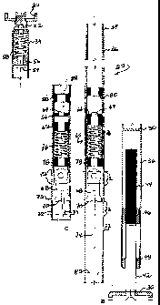
[0006] Fig. 2a is an assembly view of a post made in accordance with the
invention;
[0007] Fig. 2b is a cross-sectional view showing a top end of the post of Fig.
2a in a
compressed configuration;
[0008] Fig. 2c is a cross-sectional view of a center portion of the post of
Fig. 2a with a
lock positioned in engagement with an outer tube;
[0009] Fig. 2d is a perspective view showing the top end of the post of Fig.
2a;
[0010] Fig. 2e is a perspective view showing a bottom end of the post of Fig.
2a;
[0011] Fig. 3a is a side elevation view of the post;
[0012] Fig. 3b is a cross-sectional view drawn on line 3b-3b of Fig. 3a;
[0013] Fig. 4 is a similar view to Fig. 3a showing the post in position
between floors
of the building under construction;
-2-
CA 02475997 2004-07-28
[0014] Fig. 5 is a similar view to Fig. 4 from another side;
[0015] Fig. 6 is a side elevation view showing the post of Fig. 4 being
lowered to a
lock position;
[0016] Fig. 7 is a detail cross-sectional view of circled area 7 in Fig. 6;
[0017] Fig. 8 is a side elevation view showing the post of Fig. 6 being
returned to a
vertical orientation;
[0018] Fig. 9 is a detailed cross-sectional view of the top end of the post;
[0019] Fig. 10 is a perspective view of a portion of a fence panel and
associated fence
lock;
[0020] Fig. 11 is a similar view to Fig. 10 showing the fence lock in an
operative
locking orientation;
[0021 ] Fig. 12 is a similar view to Fig. 11 showing the fence lock in
engagement to
capture a fence post;
[0022] Fig. 13 is a top plan view of a pair of fence panels associated with a
pair of
support posts; and
[0023] Fig. 14 is a cross-sectional view of an alternative embodiment of a
support
post made in accordance with the invention.
DESCRIPTION OF PREPERRED EMBODIMENTS WITH REFERENCE TO
DRAWINGS
[0024] The invention provides a safety fence assembly generally indicated by
reference numeral 20 and consisting of a plurality of upright support posts 22
that
extend between a supporting surface or floor 24 and a ceiling 26. The posts
are
normally positioned adjacent to an opening and spaced apart by a distance
commensurate with the length of an associated fence panel or barrier 28. The
fence
panel 28 is normally positioned on the interior side of the associated support
post 22
and thus in the view of Fig. 1, the observer would be looking out of a
building, the
floor 24 and ceiling 26 having been drawn in cross-section. As will be
appreciated by
-3-
CA 02475997 2004-07-28
those skilled in the art, the safety fence assembly 20 may be used in a number
of
circumstances according to the needs at the building site.
[0025] The construction of the support post 22 is shown in more detail in
Figs. 2a
through 2e. An overall view of the support post 22 is provided in Fig. 3a
where it will
be observed that the support post has a floor engaging end or foot 30 at one
end and a
similar ceiling engaging end 32 at the opposite end with a pair of telescoping
inner
and outer tubes 34, 36 in between. As will be seen from Fig. 3b, the cross-
section of
the inner and outer tubes is square so that rotation of the outer tube 36 will
also turn
the inner tube 34, as is explained further below. The coupling of the floor
engaging
end 30 and ceiling engaging end 32 to the support post 22 will be explained in
more
details with reference to Figs. 2a to 2e.
[0026] As will be observed in the detail view of Fig. 2e, the foot 34 has a
cruciform
shape with four claws 38 each having a pair of sharp penetrating points for
firm
engagement with a supporting surface. It will be observed that the points are
spaced
apart and each has a length that is selected to limit penetration into a
supporting
surface. This configuration allows safety post 22 to come into firm engagement
with
the associated floor 24 and to penetrate any surface frost or dust which might
otherwise interfere with safe operation of the post. By limiting penetration
of the claw
into an associated surface, damage to the surface is avoided.
[0027] As will observed from Fig. 2d, the ceiling engaging end 32 has a
similar
cruciform configuration with four claws 40 of similar shape. However, it will
be
observed that the separation between opposing pairs of claws 40 in the ceiling
engaging end 32 is smaller than the separation between pairs of claws 38 in
the floor
engaging end 30. Thus, the floor engaging end 30 has a bigger "footprint" than
the
ceiling engaging end 32 for increased stability at the operatively lower end
of the
support post 22 where it needs to support any fence panels 28. Conveniently,
the floor
engaging end 30 and ceiling engaging end 32 can be nested thereby saving space
during shipping.
[0028] The floor engaging end 30 is rotatably coupled to a reduced diameter
portion
of a shaft 42 which extends upwardly in the operative orientation of the
support post
-4-
CA 02475997 2004-07-28
22. The shaft 42 is a solid steel bar that has a free end 44 that is threaded
along its
length and concealed from view inside the outer tube 36. The outer tube 36 has
an
internal nut 46 welded to its interior surface adjacent a lower end thereof
and having
complementary threads to the threaded end 44 of the shaft 42. The lower
extremity of
the outer tube 36 has a guide bushing 48 for sliding engagement with the shaft
42 and
which closes the lower end of the outer tube 36 to prevent the ingress of dirt
into the
assembly. A plate 50 is welded to the interior surface of the outer tube 36
above the
height of the threaded end 44 of the shaft 42 to prevent any dirt from falling
into the
assembly from the top of the support post 22.
[0029] The ceiling engaging end 32 is rotatably coupled to a stem 52 which is
slidingly received in the operatively upper end of the inner tube 34. The stem
52
carries a longitudinally extending pin 54 which has a head that locates
against a collar
56 welded to the interior surface of the inner tube 34. A top compression
spring 58 is
captured between the supporting collar 56 and the stem 52. Thus, the
application of
pressure to the ceiling engaging end 32 will cause the stem 52 to penetrate
into the
inner tube 34 and compress the compression spring 58 as illustrated by Fig.
2b. The
lower end of inner tube 34 supports a gravity lock assembly generally
indicated by
reference numeral 60 which is used to fix the relative position of the
telescoping inner
and outer tubes 34, 36. A supporting collar 62 is welded to an interior
surface of the
inner tube 34 a short distance from the operatively lower end of the inner
tube. The
supporting collar supports a longitudinally extending pendulum stem 64 with
associated flange 66 that, in use, extends downwardly to the lower extremity
of the
inner tube 34. At the lower end, the pendulum stem 64 is fitted into an
enlarged
portion which pivotally supports a pendulum lock 68. The pendulum lock 68
extends
longitudinally a short distance below the pendulum stem 64 and has two
oppositely
disposed fins 70 that extend outwardly and are adapted to engage into a
selected one
of a series of longitudinally spaced apertures 72 formed in the outer tube 36.
The
apertures 72 are disposed in pairs formed on opposite sides of the outer tube
36. The
number and spacing of the apertures 72 can be varied according to the degree
of
adjustability required in fixing the relative position of the inner and outer
tubes 34, 36.
It will also become apparent that the apertures 72 can be staggered and do not
need to
be provided in oppositely disposed pairs. The lower extremity of the pendulum
lock
-5-
CA 02475997 2004-07-28
68 has a longitudinally extending tongue 74 for added weight and also to
provide a
bearing surface for accessing the pendulum lock 68 if it needs to be
dislodged.
[0030] A center compressing spring 76 is captured at a lower end of the inner
tube 34
between a locating collar 78 adjacent to the pendulum lock 68 and the
supporting
collar 62 which is fixed to the inner tube 34. A stop 80 is fixed to the
interior of the
inner tube 34 to limit the upward travel of the pendulum stem 64 and flange
66.
[0031 ] The outer tube 36 also has a stop shown in Fig. 2a in the form of a
washer 82
welded into its interior surface. The stop limits the downward travel of the
inner tube
34 relative to the outer tube 36. It will be understood that the central
aperture of the
washer 82 is provided to accommodate the length of the tongue 74 from the
gravity
lock assembly 60.
[0032] The operation and installation of the support post 22 will now be
described
with reference being made to Figs. 4 to 9. Figs. 4 and 5 show the inner and
outer
telescoping tubes 34, 36 extended from each other so that the separation
between the
floor engaging end 30 and ceiling engaging end 32 approximate the height of
the
ceiling 26 from the floor 24. Once the approximate separation of the inner and
outer
tubes 34, 36 has been determined, the support post 22 is inclined as indicated
by arrow
84 in Fig. 6. Inclining the support post 22 causes the pendulum lock 68 to
pivot and
for one of the fins 70 to come into engagement with the internal surface of
the outer
tube 36. The separation between the inner and outer tubes 34, 36 is then
adjusted so
that the fm 70 of the pendulum lock 68 is brought into engagement with the
adjacent
upper aperture indicated by reference numeral 72a in Fig. 7. Selecting upper
aperture
72a fixes the relative position of inner and outer tubes 34, 36 so that the
combined
length of the support post 22 would exceed the separation between the ceiling
26 and
the floor 24. Returning the support post 22 to bring the ceiling engaging end
32 into
engagement with the ceiling 26 as indicated by arrow 86 in Fig. 8, causes the
softer
center compression spring '76 to compress against the locating collar 78 as a
downward load is applied to the inner tube 34 as indicated by arrow 88 in Fig.
2c.
Thus the center compression spring 76 operates to maintain the relative
position
between the inner and outer tubes 34, 36 while in the upright position prior
to
securement of the post.
-6-
CA 02475997 2004-07-28
[0033] To secure placement of the support post 22, the outer tube 36 together
with the
inner tube 34 are rotated on the threaded shaft 42 as indicated by arrow 90 in
Fig. 8.
The thread of the threaded end 44 and the nut 46 are formed so that a
counterclockwise rotation will bring about an upward vertical movement of the
inner
and outer tube assembly 34, 36. As pressure is applied to the ceiling engaging
end 32,
the inner tube 34 moves upwardly relative to the stem 52 thereby obscuring the
stem
from view. Conveniently the stem 52 may have a bright color applied to it such
as a
red colored band to provide a visual indication of the load being applied to
the top
compression spring 58 as observed in Fig. 2b. The inner tube 34 completely
obscures
the stem 52 when the compression spring 58 is fully loaded. It will be
appreciated
that the top compression spring 58 provides a means to respond in dynamic
fashion to
any small dimensional changes due to expansion or contraction of the floor and
ceiling.
[0034] Once positioned, the support post 22 is extremely stable and secure so
that it
can successfully withstand pull or push tension tests applied to its mid
portion thereby
complying with regulations of the applicable health and safety legislation or
other
legislation. Compliance with the safety regulations is largely attributed to
the greater
stability and improved surface contact provided by the configuration of the
floor
engaging end 30 and the ceiling engaging end 32. An added advantage of the
post 22
made in accordance with the invention is that the component parts are all
hidden in
the interior of the telescoping inner and outer tubes 34, 36 and therefore are
inaccessible to any accidental tampering which would compromise the safety of
the
post. Conveniently, there are no auxiliary tools required for proper position
of the
post and therefore the post is always ready for placement without having to
seek and
obtain the required tools. In addition, the square configuration of the inner
and outer
tubes, in combination with the counter clockwise thread, allows the tubes to
be
manually adjusted without requiring the assistance of a torque wrench,
although this
may used, if required. Because of the square cross-section, gripping of the
hands or
the need for an auxiliary tool such as a torque wrench is minimized.
[0035] In use, the support post 22 is erected at selected locations and a
plurality are
positioned at suitable distances required to support fence panels positioned
in
overlapping fashion as shown in Figs. 1 and 13 in order to form a security
barrier. As
-7-
CA 02475997 2004-07-28
shown in Fig. 1, the fence panel 28 has a generally rectangular frame which
includes a
pair of spaced oppositely disposed upright members 92. These are coupled to a
upper
horizontal member 94 and an operatively lower horizontal member 96.
Conveniently,
the lower horizontal member has a kick guard 98 attached to it and extending
the
length of the fence panel 28. A plurality of spaced horizontal and vertical
wires 100
form a grid and are attached at opposite ends to the rectangular frame formed
by the
upright members 92 and horizontal members 94, 96. A horizontal reinforcement
member is fixed to the upper horizontal member 94. A fence lock 104 is shown
in
more detail in Figs. 10 to 12 and consists of a bolt 106 which is fixed to the
upright 92
and has its threaded end extending through the upright 92 in a plane which is
parallel
to that of the rectangular frame of the fence panel 28. The inner end of the
bolt 106 is
secured to the upright 92 by welding. An L-shaped handle 108 is rotatably
mounted
to the bolt 106 and has its free end extending parallel to the bolt so that it
can be
rotated from the plane of the fence panel 28 outwardly as indicated by arrow
110 to a
parallel plane spaced from the fence panel 28. The handle 108 is captured
between a
washer 112 and a spring washer 114 to which pressure is applied with a nut
116. In
the shipping position of the fence lock 104, the handle 108 is brought to rest
against a
tab 118 that stops the handle 108 from further rotation out of the plane of
fence panel.
Once rotated into the position shown in Fig. 11, the fence panel 28 is slid in
the
direction indicated by arrow 120 to move the fence panel towards the support
post 22
and capture the post between the handle 108 and the fence panel wires 100.
[0036] It will be noted that the handle 108 is sufficiently long to
accommodate the
fence post 22 as well as the width of a second fence panel 28 positioned
between the
post 22 and the fence panel as drawn to the right of Fig. 13. It will be
appreciated that
the fence panel 28 is thereby securely captured and will not easily become
dislodged
thereby improving the safety of the safety fence assembly which simplifies
erection as
a whole. In addition, the extent of the overlap between adjoining fence panels
may be
adjusted making it more or less difficult to release of an individual panel
from the
assembly for repositioning elsewhere or dismantling of the fence assembly.
[0037] The combination of the support post according to the invention and the
fence
panel with a rotatably mounted fence lock provides numerous advantages over
the
-8-
CA 02475997 2004-07-28
prior art, in particular with respect to security and safety of workers and
their co-
workers. It also makes the product easier to use and more practical.
[0038] An alternative embodiment of the support post according to the
invention will
now be described with reference to Fig. 14.
[0039] The support post 130 in Fig. 14 has a floor engaging end 132 which is
similar
to the floor engaging end 30 of support post 22 and therefore will not be
described in
any more detail. However, it has a ceiling engaging end 134 that has an outer
surface
covering 136 made of compressible material such as rubber or synthetic
equivalents
that are mechanically equivalent to providing the compressive load applied in
the
support post 22 to the top compression spring 58. The support post 130 has an
inner
tube 138 of circular cross-section which is telescopically received in an
outer tube 140
which likewise has a circular cross-section. At the lower extremity of outer
tube 140
a threaded collar 142 is attached to its internal surface for threaded
engagement with a
threaded post 144 having a bottom end which is rotatably coupled to the floor
engaging end 132 and an upper free end which extends into the interior of the
outer
tube 140. A stop flange 146 is fixed to the upper threaded end of the post 144
to limit
the relative position of the outer tube 140 to the threaded post 144.
[0040] The outer tube 140 has a series of longitudinally spaced apertures 148
formed
in pairs on opposite sides of the outer tube. A lug 150 is rotatably coupled
to an
operatively lower end of the inner tube 138 through a bushing 152 fixed to the
inner
tube 138. The lug 150 has a pin receiving hole 154 which is adapted to align
with a
selected pair of the apertures 148 in the outer tube 140 in order to receive a
locking
pin (not shown) which traverses the outer tube 140 and the lug 150 to fix the
relative
position of the telescoping inner and outer tubes 138, 140.
[0041] In use, the telescoping inner and outer tubes 138, 140 are separated to
approximate the height separating the ceiling from the associated supporting
surface
or floor and the locking pin is inserted as described above. Final adjustments
of the
height of the support post 130 is achieved by rotating the outer tube 140 on
the
threaded post 144 so as to extend the height of the support post. By virtue of
the
bushing 152, the ceiling engaging end 134 remains fixed against the upper
-9-
CA 02475997 2011-10-12
engagement surface while the surface covering 136 is compressed. As in
the case of the support post 22, the post is adapted to adjust dynamically
to any dimensional changes as may occur due to settling, weather
conditions, drying of the cement, etc. The dynamic adjustability at the
ceiling engaging end eliminates the need to constantly check and adjust
post height in order to ensure safety.
-10-