Note: Descriptions are shown in the official language in which they were submitted.
CA 02476493 2004-08-16
WO 03/071263 PCT/SG02/00298
DEVICE FOR ISOELECTRIC FOCUSSING
FIELD
The present invention relates to a device end method for separating molecules,
in
particular macromolecules such as proteins. In particular, the invention
relates to a device
capable of charge-based separation of proteins.
BACKGROUND
The separation of molecules in a complex mixture is often desired for various
purposes. For example, a multitude of proteins exist within a cellular
environment, and in
order to aid characterisation, it is often necessary to separate these
proteins from each
I O other. Various separation techniques have been developed, each of which
rely on one or
more differing properties of the proteins to separate them from each other.
For example, sodium dodecyl sulphate-polyacrylamide gel electrophoresis (SDS-
PAGE) separates proteins according to their size. In SDS-PAGE, proteins are
denatured
and solubilised in a SDS buffer; negatively charged SDS molecules bind to the
protein,
with more molecules binding to larger proteins. On application of an electric
field, proteins
migrate in a polyaciylamide gel according to their charge (and hence size).
The electric
field is turned off to immobilise the proteins within the gel. We can refer to
techniques
such as SDS-PAGE as "single dimension" separation, as separation is based on
only one
property of the protein (in this case mass).
The analysis of complex mixtures, however, often requires more than one
separation process in order to resolve all the components present in a sample.
It is for this
reason that two dimensional (2D) separation schemes have been devised.
Two dimensional separation techniques make use of two properties of the
proteins
for separation. Separation is carned out in one dimension by use of a first
property, and
then a second dimension (which is generally orthogonal or perpendicular to the
first
CA 02476493 2004-08-16
WO 03/071263 PCT/SG02/00298
2
dimension) by means of a second property. When constructing a successful 2D
system
several criteria need to be addressed. For example, the two techniques should
base their
respective separations on as different a means as possible. Doing so will
reduce the
amount of redundant information contained in the 2D dataset. 2D techniques are
advantageous as they provide higher resolution. For example, they may be able
to resolve
several different proteins which differ only marginally in mass, but have
different charges
(such as in the case of differentially phosphorylated proteins).
Two dimensional polyacrylamide gel electrophoresis (2-D PAGE) is a popular and
currently favoured technique for protein separation (Anderson N.G., Anderson
N.L.,
Electrophoresis 1996; 17, 443-453). Proteins are first subjected to
isoelectric focusing
(TEF) in an immobilized pH gradient in the slab gel format to separate
proteins according
to their charge (pI values), a step which typically takes about 6-8 hours.
Then, the IEF gel
is placed on top of a gradient gel and electrophoresed in the presence of SDS
to separate
proteins based on their molecular mass. The separated proteins are stained for
visualization, interested bands are excised and digested with protease
followed by peptide
finger printing by mass spectrometry for protein identification (Shevchenko,
A., Jensen, O.
N., Podtelejnikov, A. V., Sagliocco, F., Wilm, M., Vorm, O., Mortensen, P.,
Boucherie,
H., Mann, M., Proc. Natl. Acad. Sci. U. S A. 1996, 93, 14440-14445; Jensen,
O.N.,
Larsen, M.R., Roepstorff, P., PROTEINS 1998, 74-89 Suppl. 2).
2-D PAGE is the current technology of choice for large scale proteomics
analysis
because 2-D PAGE is the highest resolution method fox protein separation and
the pattern
of proteins in the 2-D map is related to the properties of proteins, namely
isoelectric. point
in first dimension and molecular mass in the second dimension. Therefore, the
positions, of
proteins in 2-D map correspond to their chemical and physical properties.
These properties
can be used to identify and characterize the proteins. 2-D PAGE has been used
to analyze
human plasma proteins, and the pI and molecular weight of proteins can be used
for
detection and diagnosis of diseases in clinical analysis (Rasmussen, R. K.,
Ji, H., Eddes, J.
S., Moritz, R. L., Reid, G. E., Simpson, R. J., Dorow, D. S., ElectYOpho~eszs
1997,18,
588-598).
CA 02476493 2004-08-16
WO 03/071263 PCT/SG02/00298
3
However, 2-D PAGE is a labour intensive procedure and difficult to automate,
it
also suffers from its limitations in sensitivity and dynamic range of
detection. Virtual 2-D
gel electrophoresis has recently been developed (Ogorzalek-Loo, R. R.,
Cavalcoli, J. D.,
VanBogeler~, R. A., Mitchell, C., Loo, J. A., Moldover, B., Andrews, P.C.,
Ahal. Chem.
2001, 73, 4063-4070), where mass spectrometry replaces the size-based
separation of
SDS-PAGE in the second dimension. It has been shown that this technology is
more
sensitive than 2-D PAGE. However, the first dimension of separation is still
performed in
polyacrylamide gel, limiting the potential for high throughput analysis.
Mass spectrometry (MS) is an important analytical technique for molecular
structure characterization because of its high specificity, sensitivity and
speed (McLafferty,
F. W., Science 1981, 214, 280-287). Techniques such as electrospray ionization
(ESI),
described in Fenn, J. B., Mann, M., Meng, C. K., Wong, S. F., Whitehouse, C.
M., Science
1989, 246, 64-71, and matrix-assisted laser desorption/ionization (MALDI),
described in
Karas, M., Hillenkamp, F., A~ad. Chem. 1988, 60, 2299-2301, have greatly
extended the
1 S capacity of mass spectrometry to study non-volatile and labile
biomolecules. A variety of
.micro-separation techniques have been exploited to interface to mass
spectrometry for
molecular identification. The interface of microcolumn separation to
electrospray
ionization mass spectrometry is the most common system (Tourer, K. B., Chew.
Rev.
2001,101, 297-328), and is described for example in US Patent Number
5,993,633. Other
techniques involve for example depositing effluent from capillary
electrophoretic
separation on a MALDI target plate (Minarik M., Foret F., Karger B.L.,
Electrophoresis
2000, 21, 247-254).
In capillary zone electrophoresis (CZE) a sample is dissolved in a buffer and
the
sample is injected at one end of a separation capillary or channel. The
separation capillary
or channel may also be loaded with a uniform buffer solution, and a sample
injected at one
end. A constant voltage potential is applied along the separation channel so
that ions move
at rates corresponding to their electrophoretic mobilities. Since different
ionic species have
different charge-to-mass ratios, they separate as they migrate along the
channel. Liu et al
(2001, Anal. Chem. 73, 2147-2151) describe a 2-dimensional separation system,
which
CA 02476493 2004-08-16
WO 03/071263 PCT/SG02/00298
4
couples capillary zone electrophoresis (CE or CZE) with MALDI. Separation is
first
performed in open microchannels manufactured on glass microchips. Samples are
introduced at one end of the channel, and separated. The microchips are then
transferred to
a MALDI source after evaporation of solvent. Separation in the first dimension
occurs by a
combination of electrophoresis and electroosmosis, and electroosmotic movement
of
peptides and oligosaccharides is demonstrated.
~lectroosmosis, or electroendosmosis, is a bulk flow phenomenon which affects
separation during capillary electrophoresis, particularly in glass channels.
The velocity of
an analyte in capillary electrophoresis depends not only on the forces applied
by the
electrical potential, but also upon the rate of endoosmotic flow (EOF) within
the channel.
Endoosmotic flow is observed when an electric field is applied to a solution
contained in a
capillary with fixed charges on the capillary wall, for example, a glass
capillary wall.
Typically, charged sites are created by ionization of silanol groups on the
inner surface of
the fused silica. Silanols are weakly acidic, and ionize at pH vales above
about pH 3.
Hydrated canons in solution associate with ionized Si0- groups to from an
electrical
double layer, a static inner layer close to the surface (also known as the
Stern Layer) and a
mobile outer layer (also termed the Helmholtz plane). Upon application of an
electric field,
hydrated cations in the outer layer move towards the cathode, creating a new
flow of the
bulk liquid in the capillary in the same direction. The rate of movement is
dependent on
the field strength and the charge density of the capillary wall. The
population of charged
silanols is a function of the pH of the medium, so that the magnitude of the
EOF increases
directly with pH until all available silanols are fully oxidised.
Electroosmosis is described
in further detail in Wehr, T., Rodriguez-Diaz, R., Zhu, M., Capillary
Electrophof-esis of
P~oteihs,Marcel Dekker, Inc., New York, 1999.
Capillary isoelectric focussing (CIEF) is an equilibrium-based method of
separation that depends on a pH gradient created by carrier ampholyte.
Proteins move
under an electric field to their pI points where they carry zero charge and
are focused.
Therefore, separation and concentration occur at the same time. The
concentration of
CA 02476493 2004-08-16
WO 03/071263 PCT/SG02/00298
S
proteins at the focused zone can be increased by 100-500 times relative to the
starting
solution because the same protein in the whole capillary is focused on a
single spot.
Single point detection techniques, such as laser induced fluorescence and ESI-
MS,
have been employed to detect the separated proteins after CIEF. Focused
protein zones
need to be mobilized in order to pass through the detection point at~the end
of the tube
(Rodriguez, R., Zhu, M., Wehr, T., ,I. Ch~omatogt°. A 1997, 772, 145-
160).
MALDI, such as MALDI-MS and MALDI-TOF are important techniques for
measuring large molecular masses accurately and studying protein-ligand
interactions, but
successful interfacing with chromatography, in particular, capillary
electrophoresis, has yet
to be successfully achieved. The problem of interfacing CIEF to MALDI-MS is
because
the focused protein zone inside the capillary cannot be reached directly.
Therefore, the
a contents of the capillary need to be mobilized out of the capillary and
deposited into an
appropriate surface for subscquence MALDI ionization. This mobilization step
degrades
the resolution, increases the analysis time, and distorts the pH gradient.
Hence, the result
reproducibility is poor.
SUMMARY
According to a first aspect of~the present invention, we provide an
isoelectric
focussing (IEF) module comprising: (a), a first planar member having a channel
along
which a sample may be loaded and a component or components thereof focussed
isoelectrically; and (b) means for exposing the channel along at least a
portion~of its length
and thereby exposing the sample or components) therewithin.
Preferably, the sample or components) are accessible along the exposed channel
at
substantially the positions at which they are focussed. Preferably, the
channel comprises an
open channel which is exposed along at Ieast a portion of its length.
Preferably, the
channel comprises a linear groove formed on a surface of the first planar
member.
CA 02476493 2004-08-16
WO 03/071263 PCT/SG02/00298
6
In preferred embodiments, the channel comprises a microchannel or capillary
channel. Preferably, the microchannel or capillary channel is microfabricated
on the first
planar member.
The channel may have a width of between 1 to 500 inicrometres, more preferably
between 50 to 350 micrometres, more preferably between 50 to 350 micrometres,
most
preferably about 150 micrometers or about 175 micrometres.
The first planar member may be formed from a material selected from the group
consisting of: plastics, polymers, ceramic, glass or composite. Preferably, at
least one wall
of the channel comprises poly(methylinethacrylate) (PMMA) or polycarbonate.
Preferably,
the first planar is coated or derivatised to reduce surface charge and thereby
minimise
electroosmotic flow (EOF).
The module may comprise reservoirs for electrolyte, the reservoirs being in
electrical connection with the channel. Preferably, the reservoirs are formed
on the first
planar member adjacent to each end of the channel.
In some embodiments, the module fiufiher comprises a lid being a second planar
member, which reduces evaporation of the sample in the channel. Preferably,
the lid
comprises an elongate recess on its inner face, the recess being positioned
such that when
the lid is mated with the first planar member, no substantial leakage of
sample contained in
the channel occurs.
Preferably, the length and width of the recess are at least as great as a
channel in
the f rst planar member. In such embodiments, the reservoirs are preferably
disposed on
the Iid.
Preferably, the module comprises means for electrical connection between the
channel and the reservoir, but preventing substantial mixing of sample and
electrolyte. The
CA 02476493 2004-08-16
WO 03/071263 PCT/SG02/00298
means may comprise a semi-permeable membrane, agarose, acrylamide, agar, or a
gel
plug.
In highly preferred embodiments, the module comprises a plurality of channels
in
substantially parallel orientation.
In certain embodiments, the channel or channels comprises a closed channels)
and
the means for exposing the channels) comprises lines of weakness enabling
fracture along
a longitudinal plane of the channel(s).
Preferably, tlae module comprises a translational stage on which is mounted
the
first planar member.
There is provided, according to a second aspect of the present invention, an
apparatus for separating one or more components in a sample, the apparatus
comprising an
isoelectric focussing (TEF) module as set out in the first aspect of the
invention, together
with a module capable of separating isoelectrically focussed components
according to their
respective masses.
I S Preferably, the mass separation module comprises a module for mass
spectrometry.
Preferably, the mass separation module comprises a matrix assisted laser
desorptionlionisation mass spectrometry (MALDI-MS) module, preferably, a
matrix
assisted laser desorption/ionisation-time of flight (MALDI-T~F) module.
We provide, according to a third aspect of the present invention, a method of
separating one or more components in a sample, the method comprising the steps
of: (a)
providing an isoelectric focussing (IEF) module comprising a first planar
member having a
channel; (b) loading the channel with a sample; (c) isoelectrically focussing
a component
or components of the sample along the channel; and (d) exposing the channel
along at least
a portion of its length and thereby exposing the sample or components)
therewithin.
CA 02476493 2004-08-16
WO 03/071263 PCT/SG02/00298
The method may comprise one or more features as defined in the preferred
embodiments of the first aspect of the invention.
The method may further comprise the step of: (e) accessing one or more
components in the open channel and analysing it. Preferably, the or each
component is
analysed by mass spectrometry, preferably by MALDI-MS, more preferably by
MALDI-
TOF mass spectrometry.
Preferably, the sample comprises a MALDI matrix. Preferably, a MALDI matrix is
added to the sample subsequent, to isoelectric focussing. Preferably, the
MALDI matrix is
selected from the group consisting of Cyano-4-hydroxycinnamic acid (CHCA), 2,5-
z0 Dihydroxy benzoic acid (DHB), Alpha CCA, Sinapinic Acid (SA), 3-
hydroxypicolinic
acid (HPA), IA.A (Na~, 2-(4-Hydroxyphenylazo)benzoic acid HABA (Na~, Dithranol
(Na~, Retinoic Acid (Nay), Succinic acid, 2,6-Dihydroxyacetaphenone, Ferulic
Acid,
Caffeic acid, Glycerol and 4 Nitroaniline.
As a fourth aspect of the present invention, there is provided a method of
analysing
a molecule, the method comprising: (a) providing an elongate open channel; (b)
introducing a plurality of molecules into the elongate open channel; (c)
separating
molecules along the elongate open channel according to their isoelectric
points; (d)
accessing a molecule in the elongate open channel and analysing it.
We provide, according to a fifth aspect of the present invention, an apparatus
for
isoelectric focussing (IEF) of molecules, the apparatus comprising an elongate
channel, in
which the elongate channel is open along at least a portion of its length to
enable separated
molecules to be accessed.
The present invention, in a sixth aspect, provides a CIEF-MALDI apparatus.
CA 02476493 2004-08-16
WO 03/071263 PCT/SG02/00298
9
In a seventh aspect of the present invention, there is provided a kit
comprising a
module or apparatus as described above, together with a sample comprising
proteins to be
analysed.
According to an eighth aspect of the present invention, we provide use of an
isoelectric focussing module as described above, in combination with a mass
spectrometer,
preferably a MALDI-MS unit, more preferably a MALDI-TOF unit, for analysis of
a
protein. Preferably, such use is for proteome analysis.
We provide, according to a ninth aspect of the invention, a means for
interfacing a
capillary isoelectric focussing (CIEF) apparatus and a MALDI-MS apparatus
(preferably a
I O MALDI-TOF apparatus), the interface means comprising a channel along which
isoelectric
focussing is carried out, and means fox exposing said channel along at least a
portion of its
length and thereby exposing the sample or components) therewithiri.
Preferably, the interface comprises an open channel.
BRIEF DESCRIPTION OF THE DRAWINGS
I 5 Figure 1 is a diagram showing a plan view of a first embodiment of a
separation
device as described here, comprising a single open channel with reservoirs "in
cis" (i.e., on
the same substrate as the open channels). 1: substrate, 2: open channel, 3 and
4: anolyte
and catholyte reservoirs (electrolyte reservoirs), 31: agarose gel plug.
Figure 1B is a diagram showing a longitudinal cross section of the embodiment
of
20 the separation device shown in Figure 1 A.
Figures 2A to 2D are diagrams showing transverse cross sections of embodiments
of the separation device comprising a single open channel, illustrating
various
configurations of the open channel. Figure 2A shows a channel with straight
walls and
base. Figure 2B shows a "U" shaped channel with straight walls and a curved
base. Figure
CA 02476493 2004-08-16
WO 03/071263 PCT/SG02/00298
2C shows a "U" shaped channel with curved walls and a straight base. Figure 2D
shows a
"U" shaped channel with curved walls and a curved base.
Figure 3 is a diagram showing a longitudinal cross section of the embodiment
of
the separation device shown in Figure lA, mounted on a stage. The stage may
comprise
for example an XY-translation stage for MALDI. 5: stage, 6: laser beam.
Figures 4A to 4C are diagrams showing a second embodiment of a separation
device as described here, comprising multiple open channels with integral
reservoirs.
Figure 4A shows a plan view and Figure 4B shows a transverse cross section of
the
separation device. Figure 4C shows a longitudinal cross section of the
separation device
10 mounted on a stage, for example an XY-translation stage for MALDI. 1, 2, 3,
31, 4, 5, 6
are as described in legend to Figure lA and Figure 3.
Figures SA to SC are diagrams showing a third embodiment of a separation
device
as described here, comprising a single open channel and reservoirs "in trans"
(i.e., not on
the same substrate as the open channels). Figure SA: plan view of separation
device with
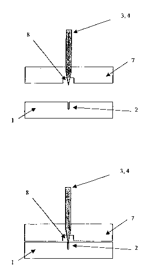
lid detached. Figure SB: plan view of device with lid in place. 7: lid, 8:
recess in lid,
shown in outline (dashed lines).
Figures 6A and 5B are diagrams showing a transverse section of the third
embodiment of Figure 5 along a plane of the reservoir. Figure 6A: open
configuration;
with lid removed. Figure 6B: closed configuration, with lid in place.
Figures 7A to 7C are diagrams showing a fourth embodiment of a separation
device as described here, comprising multiple open channels and reservoirs "in
traps", in
which the reservoirs are on a separate piece from the open channels. Figure
7A: plan view
of separation device without lid. Figure 7B: plan view of separation device
covered with
lid. Recesses (8) in Iid are shown in outline.
CA 02476493 2004-08-16
WO 03/071263 PCT/SG02/00298
11
Figures 8A and 8B are diagrams showing a transverse section of the fourth
embodiment of Figure 7 along a plane of the reservoirs. Figure 8A: open
configuration,
with Iid removed. Figure 8B: closed configuration, with lid in place.
Figure 9 is a composite photograph showing isoelectric focussing of myoglobin.
Top lane: t = 0, bottom lane: t = end of experiment. Arrow shows direction of
time.
Figure 10 is a photograph showing the separation device mounted on an adaptor
for
attachment to a MALDI sample plate. 9: adaptor.
Figure 11 is a graph showing MALDI TOF-MS of myoglobin from a focussed zone
in the separation device. X-axis: mass to charge (m/z) ratio, Y-axis:
intensity.
Figures 12A and 12B are photographs showing separation of whole porcine liver
proteins. Figure 12A: open channel with visible focussed protein (arrow), the
adjacent
ruler shows a scale and is intended to estimate the pI value. Figure 12B:
enlargement of
Figure 12A showing three visible protein spots at about 8cm, indicated by
arrows.
The practice of the present invention will employ, unless otherwise indicated,
conventional techniques of chemistry, molecular biology, microbiology,
recombinant
DNA and immunology, which are within the capabilities of a person of ordinary
skill in
the art. Such techniques are explained in the literature. See, for example, J.
Sambrook, E.
F. Fritsch, and T. Maniatis, 1989, Molecular Cloning: A Labo~ato~y Manual,
Second
Edition, Books 1-3, Cold Spring Harbor Laboratory Press; Ausubel, F. M. et al.
(1995 and
periodic supplements; Curt°ent Protocols i~z Molecular Biology, ch. 9,
13, and 16, John
Wiley & Sons, New York, N.Y.); B. Roe, J. Crabtree, and A. Kahn, 1996, DNA
Isolation
and Sequevccing: Essential Techniques, John Wiley & Sons; J. M. Polak and
James O'D.
McGee, I 990, Ire Situ Hyb~idizatio~t: P~ihciples and Practice; Oxford
University Press; M.
J. Gait (Editor), 1984, Oligohucleotide Sy~thesfs: A P~irctical Approach, Irl
Press; and, D.
M. J. Lilley and J. E. Dahlberg,1992, Methods of E~zy~ology: DNA Structure
Past A:
Synthesis and Physical Analysis of DNA Methods in Enzymology, Academic Press.
An
CA 02476493 2004-08-16
WO 03/071263 PCT/SG02/00298
12
extensive review of 2-D PAGE techniques, and their application in proteome
analysis, is
provided by Andrew J. Link, 2-D Proteome Analysis Protocols, Vol. 112 , Humana
Press
ISBN: 0896035247. Each of these general texts is herein incorporated by
reference.
DETAILED DESCRIPTION
We,disclose a module l apparatus which separates proteins using isoelectric
focussing, and which is adapted for easy interfacing with mass spectrometry,
in particular
MALDI mass spectrometry (MALD-MS). In particular, the module is adapted for
easy
interface with MALDI-TOF. In particular, our module / apparatus employs 2D
separation
using charge in a first dimension (isoelectric focussing), and mass in the
second (MALDI,
preferably MALDI-TOF).
T'he apparatus / module and method described here enables rapid and accurate
focussing of components of a sample, in particular, protein components of the
sample,
along a channel, and enabling access to these. This is achieved by providing
means for
exposing the channel along at least a portion of its length, preferably the
whole or
substantially the whole of its length. Specific embodiments of such a device
and method
are described in further detail below. Embodiments where the channel is "open"
are
preferred, and provide random access to any target protein along the
rnicrochannel. The
target protein may be extracted, or may be analysed i~c situ. The target
protein may be
removed for analysis, for example, by interfacing the channel or microchannel
to a mass
spectrometry apparatus. Use of specific MS apparatus, such as MALDI or MALDI-
TOF, is
preferred.
The module, apparatus and method described here are therefore capable of
detecting components in the sample, in particular, determining one or more
properties of
the or each component. In preferred embodiments, the module, apparatus and
method
described here is used for proteome analysis, i.e., analysing the protein
components of a
cell. The module, apparatus and method described here may also suitably be
used for
CA 02476493 2004-08-16
WO 03/071263 PCT/SG02/00298
13
detection of one or more disease associated proteins in a sample from an
individual. Such
detection may be used as, or as a means to determine, a diagnosis of a
disease.
SAMPLES AND COMPONENTS
The method and apparatus described here is suitable for separating one or more
components from a sample, which is typically a mixture of components. The
sample may
be a complex mixture, comprising hundreds or thousands of components. The
components
may be uniform iri nature, but preferably are not. In preferable aspects, two
or more of the
components may be distinguished by one or more properties, for example,
charge, mass,
etc.
~ Samples which are suitable for isoelectric focussing using our module or
apparatus
may therefore include different types. In particular, our methods and
apparatus are suitable
for separation and analysis of complex samples, for example, cell extracts.
Cell and tissue
extracts may be prepared by any means known in the art.
The samples may comprise simple molecules, complex molecules, or any mixture
of these. They may comprise proteins, carbohydrates, nucleic acids, DNA, RNA,
etc.
Preferably, at least one of the components of the sample comprises an
amphoteric
molecule, such as a protein.
The sample may comprise one or more of the following: a protein, a peptide, a
polypeptide, an amino acid, an oligonucleotide or modified oligonucleotide, an
antisense
oligonucleotide or modified antisense oligonucleotide, cDNA, genomic DNA, an
artificial
or natural chromosome (e.g. a yeast artificial chromosome) or a part thereof,
RNA,
including mRNA, tRNA, rRNA or a ribozyme, or a peptide nucleic acid (PNA); a
virus or
virus-like particles; a nucleotide or ribonucleotide or synthetic analogue
thereof, which
may be modified or unmodified; an amino acid or analogue thereof, which may be
modified or.unrnodif ed; a non-peptide (e.g., steroid) hormone; a
proteoglycan; a lipid; or a
carbohydrate, etc.
CA 02476493 2004-08-16
WO 03/071263 PCT/SG02/00298
14
Protein Cohtaihi~g Samples
Our method and device may be used to analyse any sample, in particular protein
containing samples. In preferred embodiments, the methods and apparatus
described here
is suitable for separating samples comprising proteins. Preferably, the
molecules which are
isoelectrically focussed and I or analysed comprise proteins.
The proteins may preferably be. human proteins, or animal proteins, mammalian
proteins or bacterial or other microorganism proteins. The proteins may be
native proteins,
or denatured proteins. They may comprise wild type proteins, or mutated
proteins, whether
natural or man made. They may comprise post translational modifications, for
example,
any one or more of ADP-ribosylation, ubiquitination, glycosylation,
prenylation (fatty
acylation), sentrinization, phosphotylation, etc. The proteins may comprise
one or more
post-translationally modified groups such as methyl, phosphate, ubiquitin,
glycosyl, fatty
acyl, sentrin or ADP-ribosyl moiety. Such modifications are described' for
example in WO
OOJ50896, WO 00/50635, WO OO15063I, WO 00/50630 and GB2342652. The protein may
I 5 be an isoform, and the sample may in particular comprise one or more
protein isoforms.
The proteins may comprise recombinantly expressed proteins. Methods of
producing recombinant proteins, methods of expression, vectors, and hosts
suitable for
expression are well known in the art.
Disease Associated Proteins
In preferred embodiments, the protein or proteins which is detected or
analysed
comprises ~a disease associated protein. By this term we mean a protein whose
presence in
a cell, tissue or organ of an individual is indicative of a disease state of
the cell, tissue or
organ. In preferred aspects, the protein is a flag or marker of a pathological
condition. The
protein may be a causative agent of the disease state, or it may not have any
causative
effect. The protein may be a '.'downstream" indicator of disease. The disease
associated
protein may be indicative of the presence of the disease, or susceptibility to
the disease, in
an individual.
CA 02476493 2004-08-16
WO 03/071263 PCT/SG02/00298
It will be appreciated that the disease associated protein itself need not be
detected,
and that any nucleic acid encoding it, for example, a disease associated-DNA, -
mRNA, -
gene, -allele, etc may be detected.
The disease may comprise any known disease, which affects humans or animals.
5 The disease may in particular comprise infections such as bacterial, fungal,
protozoan and
viral infections, particularly infections caused by HIV-1 or HIV-2; pain;
cancers; diabetes,
obesity; anorexia; bulimia; asthma; Parkinson's disease; thrombosis; acute
heart failure;
hypotension; hypertension; erectile dysfunction; urinary retention; metabolic
bone diseases
such as osteoporisis and osteo petrosis; angina pectoris; myocardial
infarction; ulcers;
10 asthma; allergies; rheumatoid arthritis; inflammatory bowel disease;
irritable bowel
syndrome benign prostatic hypertrophy; and psychotic and neurological
disorders,
including anxiety, schizophrenia, manic depression, delirium, dementia, severe
mental
retardation and dyskinesias, such as Huntington's disease or Gilles dela
Tourett's
syndrome. Inflammatory diseases such as psoriasis, acne, eczema, etc are also
included
15 Preferred diseases include those which afflict or threaten first world
populations,
such as AIDS, cancer, Alzheimers disease, Parkinsons, CJD, etc.
The disease associated protein for a specific disease may be one which has
previously been determined (i.e., a known disease associated protein), or it
may be
unknown. In the latter case, the methods, apparatus and module described here
may
suitably be utilised to determine the unknown disease associated protein.
A sample from a diseased individual is taken, and separated and analysed as
described. One or more profiles may be generated; these may comprise for
example, an
isoelectric focussing profile (the disposition of the various proteins along
the channel), or
preferably a mass spectrometry profile. The mass spectrometry profile will
include
information on the molecular weights of the proteins present in the disease
sample. The
disease profile is then compared with a relevant profile generated from a
normal (i.e,
undiseased) individual.
CA 02476493 2004-08-16
WO 03/071263 PCT/SG02/00298
I6
Any differences in the profile indicate differences in the protein
compositions of a
normal versus a diseased individual. Such differences may provide markers for
disease,
and be used as putative disease associated proteins. They may be detected in
other
individuals as described to determine the presence of a disease, or
susceptibility thereto.
Detection of such a disease associated protein in a cell, organ, etc, using
the
methods and apparatus described here may be used as an aid to diagnosis of the
disease
For certain diseases, such detection may be used as a direct diagnosis of the
disease.
Appropriate treatrizent may then be administered to the individual or patient
in question.
ISOELECTRIC FOCUSSING
The module makes use of isoelectric focussing along a channel, preferably a
narrow channel.
The term "isoelectric focussing" also known as IEF or electrofocusing, should
be
understood to refer to a technique in which solutes of different isoelectric
points are
caused to form stationary bands in an electric field, which is superimposed on
a (stable)
pH gradient, the pH increasing from the anode to the cathode. Preferably, the
pH gradient
is most conveniently formed by electrolysing a solution containing a mixture
of carrier
ampholytes of low molecular mass and slightly differing isoelectric points,
each of which
will move to its isoelectric region in the electric field and remain there.
In further detail, isoelectric focusing (IEF) is an electrophoretic technique
that adds
a pH gradient to the buffer solution and together with the electric field
focuses most
biological materials that are amphoteric. Amphoteric biomaterials such as
proteins,
peptides, nucleic acids, viruses, and some living cells are positively charged
in acidic
media and negatively charged in basic media. During IEF, these materials
migrate in the
pre-established pH gradient to their isoelectric point where they have no net
charge and
form stable, narrow zones. Isoelectric focusing yields such high resolution
bands because
any amphoteric biomaterial which moves away from its isoelectric point due to
diffusion
CA 02476493 2004-08-16
WO 03/071263 PCT/SG02/00298
17
or fluid movement will be returned by the combined action of the pH gradient
and electric
field. The focusing process thus purifies and concentrates sample into bands
that are
relatively stable.
Isoelectric focussing is an electrophoretic process. "Electrophoretic"
separations
refers to the migration of particles or macromolecules having a net electric
charge where
said migration is influenced by an electric field. l4ccordingly
electrophoretic separations
contemplated for use in the apparatus and method described here include
separations
performed in channels packed with gels (such as polyacrylamide, agarose and
combinations thereof) as well as separations performed in solution.
Preferably, however,
the separations take place in solution.
The term "isoelectric point" or pI, as used in this document, should be taken
to
mean the phi of the solution in which a protein or other ampholyte has zero
mobility in an
electric field; hence the pH at which the protein or other ampholyte has zero
net charge,
i.e., no charges or an equal number of positive and negative charges including
those due to
any extraneous ions bound to the ampholyte molecule. The pH value of the
isoelectric
point may depend on other ions, except hydrogen and hydroxide ions, present in
the
solution. Isoelectric point i's also known as "isoelectric pH" (IEP or IpH)
Preferably, the isoelectric focussing in the module as described here takes
place in
reduced, or preferably the absence of electroosmotic flow. This may be
achieved by use of
suitable substrates, as described in further detail below.
ISOELECTRIC FOCUSSING (IEF) MODULE
The isoelectric focussing module comprises a substrate (generally of a planar
configuration) which has a channel. The isoelectric focussing module described
here is
sometimes also referred to as a "cartridge", and the isoelectric focussing
technique and
module as "CIEF" (capillary isoelectric focussing).
CA 02476493 2004-08-16
WO 03/071263 PCT/SG02/00298
18
CHANNEL
The channel is of generally elongate disposition, and preferably linear. The
channel
may be tubular in construction, but is preferably open along at least a
portion of its length.
Preferably, the channel is open substantially along the whole of its length,
so that it has the
shape of a trough or open channel on the substrate.
'The dimensions of the channel are generally in the order of the micrometre
range.
They are compatible with for example, microcapillary dimensions. By
microcapillary or
capillary, we refer to a narrow small diameter tube, preferably one which is
capable of
exerting capillary effects on a liquid, such as water. It will be appreciated
that any
capillary, such as a glass capillary (suitably modified as described below) or
a plastic
capillary, may be used for the purposes described here in place of the
channel, provided
that it is openable to expose and enable access to the separated components.
Preferably, the channel has a linear dimension, for example, width, depth or
diameter of between 1 to 500 micrometres, preferably between 50 to 350
micrometres.
However, in preferred embodiments, the channel has a linear dimension
(preferably a
width) of between 100 to 250 micrometres, or between 50 to 350 micrometers.~In
highly
preferred embodiments, the channel has a linear dimension (preferably a width)
of about
I27 micrometers or about 150 micrometers or about 175 micrometres, most
preferably
about 175 micrometres. Where the channel is open, the depth of the channel is
generally
greater than its width.
'Fhe charnel may be engraved or carved out of the substrate, or the module may
be
cast with the channel on it using known casting techniques with appropriate
moulds. The
channel may be burned on the substrate, for example using laser engraving. The
channel
may be melted, by use of an appropriate tensioned wire, for example a platinum
wire
which has been heated (preferably by passing an electric current through it).
Preferably, the
channel is carved out of the substrate, as a groove. Machining techniques as
known in the'
art may be employed for this purpose. In preferred embodiments, channel is
excavated
CA 02476493 2004-08-16
WO 03/071263 PCT/SG02/00298
19
from the substrate such that the walls (or at least one wall of) the channel
are comprised of
the substrate material.
In highly preferred embodiments, a plurality of channels is disposed on the
substrate. In preferred embodiments, the channel or channels are formed by
laser etching,
laser ablation, injection moulding or embossing of the substrate.
'The phrase "laser etching" is intended to include any surface treatment of a
substrate using laser light to remove material from the surface of the
substrate.
Accordingly, the "laser etching" includes not only laser etching but also
laser machining,
laser ablation, and the like. The term "laser ablation" is used to refer to a
machining
process using a high-energy photon laser such as an excimer laser to ablate
features in a
suitable substrate. The excimer laser can be, for example, of the F<sub>2</sub>,
ArF, KrCl, KrF,
or XeCI type.
The term "injection moulding" is used to refer to a process for moulding
plastic or
nonplastic ceramic shapes by injecting a measured quantity of a molten plastic
or ceramic
substrate into dies (or moulds). In one embodiment of the present invention,
microanalysis
devices may be produced using injection moulding.
The term "embossing" is used to refer to a process for forming polymer, metal
or
ceramic, shapes by bringing an embossing die into contact with a pre-existing
blank of
polymer, metal or ceramic. A controlled force is applied between the embossing
die and
the pre-existing blank of material such that the pattern and shape determined
by the
embossing die is pressed into the pre-existing blank of polymer, metal or
ceramic. The
term "hot embossing" is used to refer to a process for forming polymer, metal,
or ceramic
shapes by bringing an embossing die into contact with a heated pre-existing
blank of
polymer, metal, or ceramic. The pre-existing blank of material is heated such
that it
conforms to the embossing die as a controlled force is applied between the
embossing die
and the pre-existing blank. The resulting polymer, metal, or ceramic shape is
cooled and
then removed from the embossing die.
CA 02476493 2004-08-16
WO 03/071263 PCT/SG02/00298
Open C'hahr~el
The isoelectric focussing module comprises means for exposing the channel
along
at least a porkion of its length. Exposure of the channel in this manner
thereby exposes the
sample or components) therewithin, and allows them to be accessed, preferably
for
5 MALDI analysis. In highly preferred embodiments, the channel is an "open"
channel, by
which we mean that at least a portion, preferably a substantial portion, of
the length of the
channel is not closed or sealed. In other words, in such preferred
embodiments, the
channel adopts the configuration of a trough, being open on one long side. The
opening
should be at least as wide as necessary for access to the contents of the
channel, for
10 example the samples, and preferably the separated and focussed components
of the
samples, for example, proteins. Preferably, the length of the opening
encompasses all or
substantially all of the focussed components or proteins.
However, it will be appreciated that closed channels may be used, provided
that
they are provided with means for opening them. For example, closed capillaries
may be
15 employed for isoelectric focussing, if they. are provided with fracture
points to allow them
to be split lengthways. Furthermore, a capillary may be formed by mating two
planar
members each comprising a groove. Isoelectric focussing may then be carried
out within
the capillary channel, following which the planar members may be separated for
access to
the focussed proteins.
20 SUBSTRATE
The substrate may be formed of any suitable material for isoelectric
focussing, for
example, plastics, polymers, ceramic, glass or composite materials, as known
in the art.
Generally, any non-conducting material may be suitable for use as the
substrate.
The substrate may be generally elongate, and preferably rectangular in shape.
Although any size of the substrate may be employed, the term "substrate" as
used here
preferably refers to any material that can be microfabricated, e.g., dry
etched, wet etched,
laser etched, moulded or embossed, to have desired miniaturized surface
features. In
CA 02476493 2004-08-16
WO 03/071263 PCT/SG02/00298
21
addition, microstructures can be formed on the surface of a substrate by
adding material
thereto, for example, polymer channels can be formed on the surface of a glass
substrate
using photo-imageable polyimide. Preferably, the substrate is capable of being
microfabricated in such.a manner as to form features in, on and/or through the
surface of
the substrate. Such preferred features include channels as described in fiu-
ther detail below.
The substrate can be a polymer, a ceramic, a glass, a metal, a composite
thereof, a
laminate thereof, or the like. By "composite" we mean a composition comprised
of unlike
materials. The composite may be a'block composite, e.g., an A-B-A block
composite, an
A-B-C block composite, or the like. Alternatively, the composite may be a
heterogeneous,
i.e., in which the materials are distinct or in separate phases, or
homogeneous combination
of unlike materials. As used herein, the term "composite" is used to include a
"laminate°'
composite. A "laminate" refers to a composite rriaterial formed from several
different
bonded layers of same or different materials. Other preferred composite
substrates include
polymer laminates, polymer-metal laminates, e.g., polymer coated with copper,
a ceramic-
in-metal or a polymer-in-metal composite.
Elements of the device, including but not limited to the plate comprising the
channels) may be comprised of the substrate. Furthermore, the lid or cover
plate where
present may also be comprised of the substrate.
Particularly preferred substrates are those which display low electroosmotic
flow
(EOF). For example, materials whose surface groups are not substantially
charged, for
example plastics, are suitable for this purpose. Materials with charged
surface groups may
also be used, but are less preferred. .
Glass capillary channels, for example, produce strong electro-osmotic flow
(EOF)
under applied electric field, while most of the plastic substrates do not have
many
ionizable chemical functional groups, and hence, exhibit very weak electro-
osmotic flow
(EOF) (Soper, S. A., Ford, S. M., Qi, S., McCarley, R. L., Kelly, K., Murphy,
M. C., Anal.
eheyrr. 2000, 72, 642A-651A). The EOF is an important driving force for moving
CA 02476493 2004-08-16
WO 03/071263 PCT/SG02/00298
22
chemicals inside the microchanel during capillary zone electrophoresis.
However, the EOF
has to be eliminated in capillary isoelectric focusing as described here for
the. formation of
stable pH gradient by carrier ampholyte under the applied electric field
(Wehr, T.,
Rodriguez-Diaz, R., Zhu, M., Capillary Electrophoresis of P~otei~s, Marcel
Dekker, lnc.,
New York, 1999). Plastics substrates generally do not have many ionisable
chemical
fiuictional groups , and they therefore exhibit weak electroosmotic flow (if
any). Plastic
substrates are therefore preferred as substrates.
Where materials with charged surface groups are used, for example, glass,
surface
charges should preferably be reduced by chemical modification in order to
reduce EOF.
Accordingly, glass and other similar substrates are preferably surface
treated, derivatised
or coated to reduce surface charges. Any material which is used for coating
capillary
channels in CLEF may be used for this purpose, for example acrylamide,
hydroxypropyl
cellulose, methyl cellulose, Teflon and polyvinyl alcohol.
The term "surface treatment", including preferably derivatising or coating, is
used
to refer to preparation or modification of the surface of a substrate that
will be in contact
with a sample during separation, preferably one or more walls of the channel,
whereby the
separation characteristics of the device are altered or otherwise enhanced.
Preferably, the
characteristics of the device are enhanced to reduce electroosmotic flow.
Accordingly,
"surface treatment" as used herein includes: physical surface adsorptions;
covalent
bonding of selected moieties to functional groups on the surface of treated
substrates (such
as to amine, hydroxyl or carboxylic acid groups on condensation polymers);
methods of
coating surfaces, including dynamic deactivation of treated surfaces (such as
by adding
surfactants to media), polymer grafting to the surface of treated substrates
(such as
polystyrene or divinyl-benzene) and thin-film deposition of materials.
Protocols for coating with various xriaterials are set out below. For
acrylamide
coating, the capillary or channel is washed with O.SM NaOH for 30 minutes,
then with
water for I O minutes. The capillary or channel is then washed with O.1M HCI
for 5
minutes, followed by washing with water for 30 minutes. A solution of 5
microliter/ml of
CA 02476493 2004-08-16
WO 03/071263 PCT/SG02/00298
23
gamma-methacryloxypropyltrimethoxysilane in 50:50 volume of water:acetone is
made
up, and the capillary or channel is washed for one hour in this. The capillary
or channel is
washed with 4% (wlw) acrylamide, 0.04% (v/v) N,N,N,N-
tetramethylethylenediamine
(TEMED) and O.SmglmL ammonium pexsulphate solution for 30 minutes. Finally,
the
capillary or channel is washed with water and then dried by passing nitrogen
through or
across it.
For hydroxypropyl cellulose, methyl cellulose, or polyvinyl alcohol coating,
any
one of these chemicals can be added to the sample to achieve dynamic coating
during
isoelectric focussing. Alternatively, the capillary or channel is coated
beforehand by
washing capillary with 1-S% solution (of the appropriate chemical). The
capillary or
channel is then purged with dry nitrogen. The thin layer of coating is then
immobilized on
the capillary by heating it to 140-160 degrees C.
While the above protocols may be conducted on the capillary or channel itself,
it
will be appreciated that it is possible, and may be more convenient, to treat
entire substrate
with the channel for this purpose.
Where glass substrates are used, and microfabrication techniques for example
as
commonly known in the microelectronics industry, may be employed to engrave or
etch
the channel on the glass substrate. Polymer substrates are also amenable to
microfabrication technologies, and such technologies are described in detail
in Becker, H.,
Garner, C., Electrophoresis 2002, 21, 12-26. For example, the plastic devices
can be
produced from injection moulding, laser ablation, imprinting or hot embossing.
Such
fabrication techniques allow the device to be replicated quickly for mass
production with
inexpensive methods. These allow the use of single use disposable devices in
medical
diagnostics and screenings.
:25 In highly preferred embodiments, the substrate is made of
poly(methylmethacrylate) (PMMA) or polycarbonate, and at least one wall of the
channel
comprises this material.
CA 02476493 2004-08-16
WO 03/071263 PCT/SG02/00298
24
CARRIER AMPHOLYTE
Carrier ampholytes are a heterogeneous mixture of synthetic polymers
incorporating a variety of both acidic and basic buffering groups. Ampholyte
molecules
have net charges that depend on the pH of the environment and the number and
pKs of the
particular mixture of acidic and basic groups on the particular molecule. For
isoelectric
focusing (IEF}, carrier ampholytes are introduced into the channel. In the
absence of an
electrical field, the carrier ampholytes are randomly distributed and
establish a uniform pH
throughout the geI matrix, about pH 7 when creating a pH 3-10 gradient.
When an electrical field is applied across the channel, usually through an
acid
electrode solution at the anode (+) and a basic electrode solution at the
cathode (-), all
carrier ampholytes with a net charge will start to migrate. Those with a net
negative charge
and low pI value move toward the anode, those with a net positive charge and a
high pI
value move toward the cathode, and those with no net charge (neutral) do not
move. The
ampholytes with the more extreme pI values can migrate closer to the
appropriate
electrode solution before they axe titrated to the pH equal to their pI. Thus
the pH gradient
is established by the mobile carrier ampholytes. At equilibrium, the pH at any
point in the
gel is determined by the average pI of the soluble carrier ampholytes at that
point. At the
same time, charged or neutral molecules, such as protein components of the
sample, also
move to their pI points, and are focused.
The earner ampholytes may be introduced into the channel, and an electric
field
applied to create a pH gradient. Alternatively, or in addition, the carrier
ampholytes are
mixed into the sample, and the sample containing the carrier ampholytes is
introduced into
the channel.
Under the influence of the electrical force the pH gradient will be
established by
the earner ampholytes, and the protein species migrate and focus (concentrate)
at their
isoeIectric points. The focusing effect of the electrical force is
counteracted by diffusion
which is directly proportional to the protein concentration gradient in the
zone. Eventually,
CA 02476493 2004-08-16
WO 03/071263 PCT/SG02/00298
a steady state is established where the electrokinetic transport of protein
into the zone is
exactly balanced by the diffusion out of the zone.
A large number of carrier ampholyte mixture are available giving different pH
gradients. The optimal pH gradient will depend on the purpose of the
experiment. For
5 screening purposes, a broad range interval (pH 3-10 or similar) may be used.
A narrow pH
range interval is useful for careful pI determinations or when analyzing
proteins with very
similar pI points. Generally, one should not use a narrower gradient than
necessary because
the shallower gradient will lead to longer focusing times and more diffuse
bands. When
choosing pH gradient one s$ould be aware that the interval stated by the
manufacturer can
10 only be an approximation. The exact gradient obtained depends on many
factors such as
choice of electrolyte solutions, gradient medium (PAA or agarose), focusing
time etc.
Carrier ampholyte free CIEF has been demonstrated (Huang, T., Wu, X-Z.,
Pawliszyn, J., A~tal. Cherri. 2000, 72, 4758-4761), and it is possible to use
the methods
described in Huang and Pawliszyn for the isoelectric focussing technique
described here.
15 Furthermore, it will be appreciated that the pH gradient in the channel can
also been
generated by immobilizing acidic or basic ampholytic molecules on the open
channel
surface. This is described in detail in Rosengren, A., Bjellqvist, B.,
Gaspaxic, V., US
Patent Number 4130470, 1978. However, the use of carrier ampholytes is
preferred
A carrier ampholyte which may be used for the isoelectric focussing using the
20 module and apparatus described here is Pharmalyte 3-10, or BioRad 3-10.
This may be
used typically from 0.8% to 4% or more, preferably about 1%. Carrier
ampholytes are
described in detail in US Patent No 4,131,534.
Glycerol is a common additive for IEF, as it can prevent proteins
precipitation
when proteins concentration increase around their pI points. The glycerol is
also an
25 infrared (IR) MALDI matrix for protein ionization. The use of glycerol is
preferred in the
isoelectric focussing techniques when it is coupled to IR-MALDI-MS.
CA 02476493 2004-08-16
WO 03/071263 PCT/SG02/00298
26
MASS SPECTROMETRY
(The text in this and the next section describing MALDI-MS and -TOF is adapted
from an article in The Scientist 13[12]:18, Jun. 07, 1999).
The methods described here typically employ separation using IEF in a first
S dimension, and separation by mass in a second dimension. The mass separation
is
preferably carried out by mass spectrometry. The IEF module is preferably
coupled to a
mass spectrometer for separation and detection in the second dimension.
Mass spectrometry (MS) systems typically employ components for smashing and
ionizing the target molecules by applying energy and for analyzing the
results. Typically,
the molecules aye ionised by bombardment with an electron beam, high-energy
ions, or a
laser. Ionization charges some of the sample molecules, which can either
remain intact or
fragment.into a variety of charged and neutral particles. The ions are
accelerated by an
electrostatic or magnetic field in the mass analyzer and separated by
deflection or time of
flight to the detector. Some mass analyzers can differentiate between oxygen
at 15.999 Da
and the similarly sized NH2 ion at 16.021 Da. Mass accuracy is generally cited
in parts per
million (ppm), and many systems claim mass accuracies of 100-200 ppm. A review
of
the considerations for designing mass analysers is provided by Brunee (1987,
International
.Iourhal ofMass SpectYOmetry and Ion Processes, 76:125-237).
Two types of ion detectors are typically employed in mass spectrometers:
electron
multipliers and microchannel plates. Both technologies are well suited to ion
detection.,
although electron multipliers (which consist 'of several layers of charged
dynodes) are
considered more stable to high ion flux.
The first widely available configurations for MS included an electron beam
ionization source, a scanning quadrupole mass filter, and a multidynode ion
detector and
were suited primarily for analysis of smaller molecules. MS first became
useful for protein
research when fast atom bombardment (FAB) ionization sources were designed to
smash
CA 02476493 2004-08-16
WO 03/071263 PCT/SG02/00298
27
larger molecules (including proteins and peptides up to ~10 kDa) into
manageable pieces.
FAB uses a high-energy (S-10 keV) stream of inert gas particles to
"ballistically ionize"
the sample. It is limited by a relatively poor e~ciency of target ionization
and can lead to
high backgrounds when the ionizing particles themselves break up, ionize, and
impact the
detector.
Electron spray ionization (ESI) increased the protein mass range to 100 k Da.
Quadrupole and magnetic sector ESI MS became very valuable tools. ESI uses a
high
electric f eld to aerosolize a solution of the target analyte; the droplets
subdivide until they
contain a single analyte mblecule that carries a residual charge. ,Often, ESI-
produced ions
carry multiple charges, which can be a benefit or a problem, depending on your
instrument
and application. Neither FAB nor ESI is suited to working with samples in bulk
form or on
a solid support.
For proteins, ESI MS has in many ways been superseded by MALDI as the
hammer and by time-of flight mass analyzer tubes as the detector. The methods
and
apparatus described here preferably employs a MALDI mass spectrometer for
separation
and detection in the second dimension.
MATRIX-ASSISTED LASER DESORPTION/IONIZATION (MALDI)
Matrix-assisted laser desorption/ionization-time of flight (MALDI-TOF) mass
spectrometry is a tool for large-molecule analyses, especially for proteins.
MALDI-TOF is
capable of distinguishing protein and nucleic acid sequence, structure,
purity,
heterogeneity, cleavage, posttranslational modification, and other molecular
characteristics
that are often di~cult to study by other means. MALDI is described in detail
in Chapman,
J. R., Mass Spectrometry of Proteins and Peptides, 2001,Humana Press, Dass,
C.,
Principles and practice of biological mass spectrometry, 2001, John Wiley &
Sons, James,
P., Proteome research: mass spectrometry, 2001, Springer, Kellner, R., F.
Lottspeich, and
H. E. Meyer, Microcharacterization of Proteins, 2nd Ed, 1999, Wiley-VCH,
Kinter, M.,
and N. E. Sherman, Protein Sequencing and Identification Using Tandem Mass
CA 02476493 2004-08-16
WO 03/071263 PCT/SG02/00298
28
Spectrometry, 2000, Wiley Interscience and Siuzdak, G., Mass Spectrometry for
Biotechnology, 1996, Academic Press
MALDI uses pulses of laser light to desorb the analyte from a solid phase
directly
to an ionized gaseous state. Pulsed lasers had been used to ionize proteins
prior to 1988,
but the technique was limited due to protein light absorption. A metal powder
matrix for
laser desorption and ionization of analytes was first presented in 1987 by
Koichi Tanaka
and colleagues (K. Tanaka et al., Shimadzu Corp., Kyoto, Japan, "Proceedings
of the 2nd
Japan-China Joint Symposium on Mass Spectrometry," 185, 1987).
The more common MALDI method using an organic photoactive compound was
IO published in 1988 by Michael Karas and Franz Hillenkamp (M. Karas, F.
Hillenkamp,
"Laser desorption of proteins with molecular masses exceeding 10,000 Daltons,"
Analytical Chemistry, 60:2299, 1988) and has been more recently reviewed by
Ronald
Beavis and Brian Chait (R.C. Beavis, B. Chait, "Matrix assisted laser
desorption ionization
mass-spectrometry of proteins," Methods inE~zymology, 290:519, 1996).
1 S In MALDI, the protein is embedded in a medium or matrix by
cocrystallization
with a photoactive compound such as gentisic acid, 4-HCCA (alpha-cyano-4-
hydroxycinnamic acid), or dithranol. The typical matrix for use with
ultraviolet lasers is an
aromatic acid with a chromophore that strongly absorbs the laser wavelength.
Other laser
wavelengths are possible, in particular the mid-infrared range where the
matrix can be
20 energized by vibrational excitation; different matrix compounds must be
used in this case.
The MALDI matrix must meet a number of requirements simultaneously: be able to
embed an isolate analytes (e.g., by co-crystallization), be soluble in
solvents compatible
with analyte, be vacuum stable, be able to absorb the laser wavelength, cause
co-
desorption of the analyte upon laser irradiation and promote analyte
ionization.
25 The matrix compound absorbs the light and uses the energy to eject and
ionize the
embedded protein molecules. As the protein does not fragment during
desorption, MALDI
is often referred to as being a "soft" ionization technique. The list of
suitable matrix
CA 02476493 2004-08-16
WO 03/071263 PCT/SG02/00298
29
compounds for MALDI is extensive, and include Cyano-4-hydroxycinnamic acid
(CHCA),
2,5-Dihydroxy benzoic acid (DHB), Alpha CCA, Sinapinic Acid (SA), 3-
hydroxypicolinic
acid (IiPA), IAA (Na+), 2-(4-Hydroxyphenylazo)benzoic acid HABA (Nab),
Dithranol
(Na~, Retinoic Acid (Nab), Succinic acid, 2,6-Dihydroxyacetophenone, Ferulic
Acid,
Caffeic acid, Glycerol and 4-Nitroaniline. Preferably, the matrix is added to
the dried
sample after isoelectric focussing. Alternatively, or in addition, the matrix
may be added to
the sample such that it is present during the isoelectric focussing.
Although other options are available, most MALDI techniques typically
illuminate
at about 20 mJ cm 2 using nitrogen lasers (337 nm) or Q-switched
neodymium:yttrium-
aluminum-garnet (Nd-YAG) lasers with frequency tripled to 355 nm or quadrupled
to 266
nm. Longer wavelengths are favored for protein work because they are less
readily
absorbed.
Magnetic sector and quadrupole mass spectrometers work by accelerating a
stream
of ionized sample along a vacuum tube toward an electrostatic or magnetic
field that
deflects or filters particles based on momentum or mass-to-charge ratio (m/z).
A good
review of MS detectors can be found in Brunee (1987, Iv~te~hational Journal
ofMass
Spectrometry ana'loh Processes, 76:125-237).
In time of flight mass spectrometry (TOF MS), the ionized analyte molecules
and
fragments are accelerated in an electrostatic field to a common kinetic
energy. If all the
ions have the same initial kinetic energy, lighter ions travel faster and
heavier ions with the
same momentum travel more slowly. The ionized particles enter at one end of
the time-of
flight tube, which typically comprises a long, empty tube for free flight, and
the number of
ions reaching a detector at the other end is recorded in a time-dependent
manner.
Assuming alI the ions have the same electrical charge, the lightest ions reach
the detector
first and the heaviest arrive last. The entire mass spectrum is typically
recorded in a
fraction of a second as ion flux versus time.
CA 02476493 2004-08-16
WO 03/071263 PCT/SG02/00298
For TOF to work, the time at which the ions leave the source must be precisely
controlled and defined. While MALDI ionization techniques have been coupled
with
quadrupole ion and magnetic sector mass analyzers, the commonest modern
combination
is with time-of flight tubes, because the ionization event automatically
provides the start
5 pulse for the clock. The short duration of laser pulsing makes MALDI a
particularly
suitable match for TOF MS. Typically, flight-tube lengths are a couple of
meters and flight
times are 100 ms--thousands of times longer than the nanosecond laser pulses.
The mass range of a TOF instrument is generally limited by the detector
technology
employed. The high m/z ions end up travelling very slowly and are very poorly
detected by
10 conventional detectors. Instruments such as GSG Analytical Instruments'
Future MALDI-
TOF spectrometer extend the mass range of MALDI-TOF out to 1,000,000 Da with
the
help of a two-stage detector that captures the high m/z particles more
effectively and a fast
(lGHz) digitizer to increase resolution. Accordingly, such instruments are
preferred for
use in detecting high molecular weight entities in the methods and apparatus
described
15 here.
The simplest TOF instruments have a linear configuration, with the detector
placed
at the end of the flight tube; this is a typical configuration in. MALDI-TOF
instruments
which are currently available.
During sample desorption and ionization, analyte particles can leave the
surface of
20 the protein-matrix cocrystal with a small but variable amount of kinetic
energy in addition
to the energy imparted by the acceleration process. This variable kinetic
energy has the
effect of "smearing" the mass-to-charge ratio of a specific analyte fragment
over a small
time range, decreasing the signal-to-noise ratio and broadening the analyte
bands, but it
can be largely eliminated in a couple of ways. The first is time lag focusing
or delayed
25 extraction, in which newly formed ions are held close to the surface of the
protein-matrix
cocrysta.l with a low voltage (generally 1 keV or so) pulse before applying
the main
acceleration pulse (generally 20-30 keV). Most instruments now incorporate
this feature.
Time lag focusing or delayed extraction is described in further detail in W.C.
Wiley, LH.
CA 02476493 2004-08-16
WO 03/071263 PCT/SG02/00298
31
McLaren, Review of Scientific Iust~uments, 26:1150-7, 1955 and B. Spengler,
R.J. Cotter,
"Ultraviolet Iaser desorption/ionization mass spectrometry of proteins above
100,000
Daltons by pulsed ion extraction time of flight analysis," Analytical
Chemistry, 62:793-6,
1990.
The second way to focus an ion band is to change the TOF geometry by adding a
reflection to the end of the flight tube and moving the detector(s). A
reflection or "ion
mirror" consists of a series of electrostatic and magnetic fields that collect
and redirect the
ions in a controlled manner. Ions with a given m/z slow down as they approach
the
reflection mirror, focus into a tighter packet, and are then repelled either
at an angle
toward a detector at the end of a second stage of flight tube or backward
along the same
tube to a detector placed near the ion source. For many applications,
reflection-based TOF
tubes give sharper signals by reducing the effects of initial kinetic energy
differences.
Because reflections effectively increase--almost double--the TOF free-flight
path,
they increase resolution and therefore improve mass accuracy. Reflection
technology also .
allows researchers to study molecular structure of ions via postsource decay,
in which
ionized fragments decompose further in the flight tube and the secondary
products provide
additional information about the structure of the original ion. The
information gained from
postsource decay detection is similar to that provided by tandem MS (MS/MS),
where ions
are intentionally refragmented after passage through a mass analyzer and the
secondary
fragmentation products are examined in a second mass analyzer.
Examples of reflection-based MALDI-TOF instruments include Comstock's
RTOF-260 instrument, which is a reflection-based version of its LTOF-160.
PerSeptive
Biosystems (a division of PE Biosystems) offers the Voyager DETM workstation,
4700
TOF/TOF and the Voyager DE-PRO.
Micromass and Kore produce the TofSpec-2E and R-500 TOF MS, respectively.
The M@LDI, made by Micromass, rnay also be used.
CA 02476493 2004-08-16
WO 03/071263 PCT/SG02/00298
32
The several reflectron systems offered by Bruker Daltonics, including the
customizable REFLEX III system and the BIFLEX III system for high-end
research, the
Autoflex and the Ultraflex, may also be used.
Reflectron-based instruments, such as the Kompact DISCOVERY and the
Kompact SEQ, made by Kratos Analytical, a Shimadzu company, may also be used.
Kratos' reflectrons have a design incorporating a curved field rather than
stepped or tiered
linear fields. In normal ion reflection configurations, many of the postsource
decay ions
are "out of time-focus" and are therefore lost. Most instruments collect only
about 10
percent of the range of postsource decay particles, necessitating repeated
experiments at
different collection points. The curved field allows collection of the entire
range of
postsource decay products from one laser pulse without rastering or scanning
and
eliminates the need to~compile data from sequential experiments. Shimadzu also
produces
the AXIMA-CFR-plus and AXIMA-QIT.
Multisample target formats are becoming more important to users, and many
companies have started to offer them. For example, BioMolecular Instruments, a
division
of Thermo BioAnalysis, recently introduced the Dynamo, which is highly
automated and
incorporates a video camera in the ionization chamber for direct sample
monitoring. The
Bruker REFLEX III and BIFLEX III instruments both offer integration with
Bruker's
SCOUT 384 automated sampler. The SCOUT 384 uses standard microtiter plate
formats
and an X-Y positioner with 4 mm accuracy for unattended data acquisition from
up to
1,536 samples.
It will be appreciated that other MALDI mass spectrometers, other than MALDI-
TOF spectrometers, rnay be used. For example, FTMS (Fourier Transform Mass
Spectrometers) may also be.used or combined with the module as described here.
CA 02476493 2004-08-16
WO 03/071263 PCT/SG02/00298
33
SPECIFIC EMBODIMENTS
Preferred embodiments of the present invention will now be described with
reference to the accompanying Figures, wherein like numerals refer to like
elements
throughout. The terminology used in the description presented herein is
intended to be
interpreted in its broadest reasonable manner, even though it is being
utilized in
conjunction with a detailed description of certain specific preferred
embodiments of the
present invention. This is further emphasized below with respect to some
particular terms
used herein. Any terminology intended to be interpreted by the reader in any
restricted
manner will be overtly and specifically defined as such in this specification.
Figures lA and 1B show a first embodiment of the isoelectric focussing module
with a single microchannel. Module comprises a substrate 1 of generally planar
configuration, made of poly(methylmethacrylate) (PMMA) or polycarbonate. The
substrate
1 comprises a piece of a PMMA plate having dimensions of 90 mm x 30 mm x 3 mm.
A
channel 2, which in this embodiment is an open channel, is carved, built or
etched out of
the substrate. Reservoirs 3 and 4 machined from the substrate and are
positioned at
opposite sides of the channel and carry electrolyte (anolyte and catholyte).
The reservoirs
3, 4 are separated from the open channel by agarose plugs 31. The agarose
plugs are set in
the boundary of the reservoir and the channel, and allow electrical
conductivity to be
maintained between the electrolyte solution and the contents of the channel
(typically a
sample to be separated, see below). Mixing between the contents of the channel
and the
reservoir is prevented, however, by the presence of the agarose plugs. Mixing
may also be
prevented by the use of a gel plug, such as an acrylamide gel plug or an agar
gel plug, or
any other suitable gel plug which prevents mixing but conducts electricity.
Mixing may be
prevented by increasing the viscosity of the sample, by for example, adding
glycerol to it.
The viscosity of the electrolytes, or one or both of the anolyte and
catholyte, may be
increased alternatively, or in addition to increasing the viscosity of the
sample. For
example, methylcellulose may be. added to the or each electrolyte(s).
CA 02476493 2004-08-16
WO 03/071263 PCT/SG02/00298
34
It will be understood that the presence of the agarose or gel plug is
optional,
provided that mixing is minimised. For example, the channel may have a
narrower profile
at the region where it joins the reservoir; the narrow portion will
substantially reduce
convection and therefore any mixing between the components of the channel and
the
reservoir.
Figures 4A to 4C show a second embodiment of the isoelectric focussing module,
which contains multiple channels 2. Each of the channels in this embodiment
may be
fabricated as described above for the single channel embodiment. In a
preferred
embodiment, the channels are parallel with each other, or substantially so.
The channels
may each have individual reservoirs 3, 4 connected to them, or preferably may
be joined'at
each end to a common reservoir 3, 4 shared by all the channels. As described
above, each
channel may preferably have an agarose gel or plug, preferably at each end, to
reduce
mixing with the electrolyte contents of the reservoir.
The channel or microchannel 2 can have a variety of shapes or profiles;
indeed, any
profile which is conducive to isoelectric focussing and open at one edge may
be used.
Examples of individual channel profiles are shown in Figures 2A to 2D. Thus,
the channel
2 may have a flat bottom and straight walls, so that it adopts a flat U shape
(Figure 2A).
The channel 2 may have a curved or bowed or convex profile, and straight
walls, thus
having a typical "U" shape (Figure 2B. The channel 2 may have curved walls and
a
straight base (Figure 2C) or substantially curved walls adopting a curved "V"
shape
(Figure 2D). A variant of the profile of Figure 2D, with straight walls, i.e.,
a straight "V"
shape, may be employed. In each of these cases, the channel may be carved,
etched, or
gouged out of the substrate 1. Figure 4B shows a profile of the module in a
second
embodiment of the device, showing the multiple channels 2 on the substrate 1.
In the f rst and second embodiments described above, the reservoirs 3, 4 are
provided on the same piece of substrate as the channel, i.e., they are
provided "in cis"
CA 02476493 2004-08-16
WO 03/071263 PCT/SG02/00298
3S
In other embodiments of the module or device, however, the reservoirs are not
located on the same substrate as the channel. Rather, they are provided on a
separate lid or
cover plate 7, as illustrated for a third embodiment in Figures SA to SC. As
can be seen
from Figure SB and SC, a separate cover plate or lid 7 is provided to hold the
reservoirs 3,
S 4. The reservoirs 3 and 4 may be provided as tubular compartments, which are
capable of
holding electrolyte. They may for example have a conical shape, or a cylinder
having a
conical end. In the embodiment shown in Figures SA to SC, the electrolyte
reservoirs are
modified from a micropipette with a sharp tip of about 10 ~,m. They are
attached to the
cover plate as shown in Figure 5C, 6A and 6B. In such embodiments, the
reservoirs 3, 4
can be said to be provided "in t~av~s".
The tips of the micropipettes are filled with a thin layer of agarose gel to
prevent
mixing of the electrolytes and the sample while allowing ions to migrate
through the
junction. It will be seen from Figures SC, 6A and 6B that distal portions of
the reservoirs
3, 4 extend across the lid 7, and mate with respective ends of the channels 2
when the lid is
1 S placed on the substrate 1. For this purpose, suitably sized and positioned
holes may be
drilled on the lid 7 to hold the reservoirs 3, 4 in position.
The lid or cover plate 7 and the base 1 may further comprise guiding means 7I,
as
shown in Figures SA, SB, 7A and '7B for guiding the lid 7 to overlay the base
or substrate
1. The guiding means may comprise markings on the lid 7 and substrate 1, or
preferably
physical guiding means such as a peg and hole arrangement, a tongue and groove
arrangement, ete. Preferably, the lid 7 comprises a hole 71 and the base or
substrate 1
comprises a peg or post 71 (or vice versa). The guiding means enables precise
alignment
between the base and the lid, so that the channels and recesses are matched to
their correct
positions, and the outlets of the electrolyte reservoirs are pointed to the
channels.
ZS Preferably the guiding means 71 is asymmetrically placed on the lid and
base, so that the
two can only be mated in one orientation.
The cover plate 7 preferably is not completely flat, particular at points
abutting the
channel or channels. This is because a completely flat cover plate would cause
the sample
CA 02476493 2004-08-16
WO 03/071263 PCT/SG02/00298
36
in the microchannel 2 to contact the cover plate 7 and thereby diffuse out of
the channel to
the gap between two plates by capillary action. Accordingly, in a preferred
embodiment,
the lid or cover plate 7 comprises one or more grooves or recesses 8,
preferably the same
number of recesses as there are channels, on one face (i.e., the face which
abuts the
microchannels when the lid is in place). The or each groove or recess is
positioned such
that when the lid is mated with the first planar member, no substantial
leakage of sample
contained in the channel occurs. Preferably, the length and width of the
recess or recesses
are at least as great as a channel or respective channels in the first planar
riiember. The
grooves may be machined on the corresponding opposite side of the microchannel
on the
I O cover plate to prevent the sample from diffusing out to the gap. The
arrangement of
recesses 8 on the cover plate 7 is shown in Figures 6A (lid open) and 6B (lid
closed).
Figures 7A to 7C show a fourth embodiment of the isoelectric focussing module,
which is' identical with the third embodiment except that it contains multiple
channels 2.
Each of the channels in this embodiment may be fabricated as described above
for the
single channel embodiment. In a preferred embodiment, the channels are
parallel with each
other, or substantially so. The reservoirs 3, 4, serving the channels are
located on a
separate lid or cover plate 7, as described above. Each reservoir may
preferably have an
agarose gel or plug, to prevent or reduce mixing between the electrolyte
contents of the
reservoir, and the contents of the channels. A profile showing the arrangement
of the
multiple reservoirs 3, 4 on the Iid 7, and the recesses or grooves 8, together
with the
substrate I comprising multiple channels 2, is shown in Figure 8A (lid open)
and Figure
SB (Iid closed).
The use of a lid in the third and fourth embodiments is advantageous in that
it
reduces evaporation of the sample in the channel or channels. evaporation is a
particular
problem because of the small volume and large surface area of the sample in
the channel.
The lid maintains a humid atmosphere above the sample, and prevents drying
out.
Furthermore, the presence of a cover also prevents carbon dioxide from the air
dissolving
into the sample, and perturbing the pl=I gradient established.
CA 02476493 2004-08-16
WO 03/071263 PCT/SG02/00298
37
It will be appreciated, however, that the presence of a cover is not strictly
necessary, and other means may be used to control drying and pH perturbation.
For
example, isoelectric focussing with embodiments one and two with open channels
may be
carried out in a controlled atmosphere, particularly one with humidity
conducive to non-
evaporation (i.e., one high in humidity - high relative humidity). Therefore,
a humidity
controlled chamber may be used. Furthermore, the controlled atmosphere may be
depleted
of carbon dioxide. For this purpose, a simple air-tight chamber may be used;
the chamber
may contain a carbon dioxide depleting agent, such as an alkali metal
hydroxide (NaOH,
KOH) or an alkaline metal hydroxide (C~.(OH)a), or other chemicals such as
NaC03, etc.
The chamber may comprise a mister, or simply a source of water, for
maintaining high
humidity.
Furthermore, or alternatively, evaporation may be reduced by reducing the
vapour
pressure of the solvent in the sample, for example by cooling. For this
purpose, the
temperature of the module or the substrate, or its surroundings may be
reduced. For this
purpose, the cartridge or module is mounted on an aluminium block which in
turn was
immersed in an ice bath. The temperature can also be controlled by attaching
the cartridge
or module onto a thermoelectric cooler.
For isoelectric focussing in the module, anolyte and catholyte are introduced
into
the reservoirs. I00 mM potassium hydroxide in 1.5% methylcellulose is used as
catholyte
and 50 mM phosphoric acid in 1.5% methylcellulose is used as anolyte. A sample
- for
example a sample containing proteins such as a cell extract - is introduced
into the
channel. As the module and device are particularly useful for separation and
analysis of
proteins in cell, tissue, or organ samples, the following description will be
based on
separation of such proteins in cellular samples.
The sample may contain a carrier ampholyte as known in the art, and as
described
above. A voltage of from about 500V to 5kV is then applied across the channel
2 by means
of electrodes introduced into the reservoirs 3 and 4. For this purpose, the
module or
apparatus may comprise a power supply (not shown), which is capable of
generating an
CA 02476493 2004-08-16
WO 03/071263 PCT/SG02/00298
38
electrical potential between two points, preferably the electrodes 3, 4. The
power supply is
preferably a DC power supply, as known in the art for use in electrophoresis
devices..
Examples include, but are not limited to, PowerPac Basic power supply,
PowerPac 3000
power supply, PowerPac 1000 power supply, PowerPac 200 power supply, and
PowerPac
300 power supply, produced by BioRad. Other suitable power supplies include
the ECI05
Power Supply, EC135-90 Power Supply, EC250-90 Power Supply, EC4000P
Programmable High Voltage Power Supply, EC570-90 Power Supply, EC600-90 High
Voltage Power Supply, EC6000-90 High Voltage Power Supply, EC PR06000 Power
Supply, EC1000-90 Power Supply, made by Thermo EC (Thermo Savant / Thermo EC
Holbrook, NY, United States).
The power supply may be linked to the electrodes 3, 4 by means of wires. The
power supply may further comprise control means, by which an operator is able
to confirol
various parameters. For example, the control means may allow the operator to
vary the
potential difference (voltage). The control means may enable the current to be
modified,
for example, the current across the channel. Control of the voltage and
current is
advantageous because it enables the amount of Joule heating (voltage x
current) to be
adj usted.
Application of the voltage across the channel causes a pH gradient to develop
along it, as described in detail above. The molecules, proteins or other
components of the
sample then migrate along the channel and are focussed at points according to
their
respective pI points. Isoelectric separation and focussing of the
components'therefore takes
place along the channel.
The voltage is applied for a suitable amount of time to allow focussing, for
example, about 5 minutes. Protein focussing into a narrow zone is indicated by
a drop in
the focusing current to a constant value. Following this, the voltage applied
across the
capillary channel may be gradually increased to tighten the focusing zones.
The use of
modules comprising multiple channels (e.g., embodiments two and four described
above)
CA 02476493 2004-08-16
WO 03/071263 PCT/SG02/00298
39
is advantageous, as many different samples may be processed at the same time.
Migration
and focussing of the proteins may also be monitored by means of suitable
stains.
After the proteins are separated, the sample is dried to retain the separated
components of the sample, for example proteins, at the points at which they
are focussed.
Any suitable means for removing the solvent in the sample may be used, for
example,
application of a stream of warm air, preferably dry air over the module.
Lyophilisation,
vacuum drying or freeze drying, may also be employed for this purpose.
Application of an
electrical potential across the channel, which causes Joule heating, may be
employed to
evaporate the solvent. Proteins "frozen" in position are accessible because of
the open
nature of the channel, and may then be analysed by any suitable means. In
preferred
' embodiments, a mass spectrometry technique is used to analyse the proteins,
for example .
MALDI-TOP. For this purpose, and as noted above, the MALDI matrix may be added
to
the sample. Alternatively, it may be applied to the dried focussed proteins in
the channel.
The isoelectric focussing module may or may not then be coated with an
electrical
conducting thin film or layer by different means before performing MALDI-MS.
The
conductive coating may be achieved by vacuum deposition of metallic or
conductive layer,
or by painting a layer of conductivematerial, or by use of conductive adhesive
tape, or by
other methods. In the preferred embodiment, the isoelectric focussing module
is not coated
with any conductive coating.
The isoeIectric focussing module (including substrate comprising the channels)
is
then mounted on a standard MALDI plate for the MALDI procedures. The cartridge
may
therefore be loaded into a translational stage, for example an X-Y
translational stage, in the
MALDI ionization source. The isoelectric focussing module may be mounted
directly on
the MALDI plate, or the isoelectric focussing microchannel may be fabricated
directly on
the MALDI plate, or an adapter may be fabricated to hold the isoelectric
focussing module
onto the MALDI plate. Figures 3 (and also Figure 4C) shows a cross section of
a module
comprising the planar substrate and channel, which is mounted on a stage or
adapter 5.
The adaptor 5 is also depicted in Figure 10. The MALDI laser 6 is then
focussed on the
CA 02476493 2004-08-16
WO 03/071263 PCT/SG02/00298
centre of the channel or microchannel, and the MALDI plate is moved slowly
across the
laser 6, while maintaining the laser beam 6 on the centre of the channel. The
translational
stage may be moved to consecutively bring the whole open channel to the
focused laser
spot. The MALDI laser 6 ionizes the proteins, and analysed using time of
flight (TOF} or
5 other means as described in detail above. The protein molecular ions from
the MALDI
source may be fragmented by post source decay or collisionally activated
dissociation for
protein identification. '
In highly preferred embodiments, the separation of protein samples in open
channels is preferably done in parallel fo~nat where multiple microchannels
are built on a
10 cartridge. Such embodiments are the second. and fourth embodiments,
illustrated in Figures
4A-C and 7A-C.
The parallel CIEF separation can take less than 5 minutes. The detection of
protein
in the second dimension requires scanning the channel over the focused laser
in the MS
ionization source region. How fast the channel for MALDI ionization may be
moved
15 depends on the repetition rate of the desorption/ionization laser. Nitrogen
lasers commonly
used in MALDI normally operate at 10-20 Hz. However, diode-pump solid state
lasers can
operate in several kHz repetition rates, and are therefore preferred.
Therefore, in such
preferred embodiments, a complete scan of the whole channel using such lasers
can be
completed within minutes. High throughput, high sensitive protein separation
and
20 characterization through their pI points and molecular weights can be
achieved using our
apparatus with minimal sample consumption for clinical application.
The protein ionization process can be significantly suppressed by impurity and
salts. Separation of the sample components by open channel CIEF prior to the
MALDI-MS
analysis minimizes the potential of signal suppression due to the presence of
other sample
25 components in same spot. The effect of salts (cations and anions) in the
sample can be
rriinimized because ions will migrate out of the separation channel under the
influence of
the applied electric field. The focused laser into small spot provides high
spatial resolution
allowing analysis of sample only a few micro meter size. Therefore, the high
resolution
CA 02476493 2004-08-16
WO 03/071263 PCT/SG02/00298
41
separation of proteins by capillary isoelectric focusing can be retained in
the second
dimension by laser desorption/ionization. Open channel CLEF-MALDI as described
in this
document is expected to have high sensitivity because the focused proteins are
concentrated on a small spot in a narrow channel.
The invention is described further, for the purpose of illustration only, in
the
following examples.
EXAMPLES
Example 1. Materials and Reagents
Poly(methylmethacrylate) (PMMA) is purchased from a local supplier (Swees
Engineering Co. (PTE) Ltd.). Myoglobin, glycerol, pharmalyte, methylcellulose
are
ordered from Sigma Chemicals. All other chemicals are acquired from Aldrich
Chemicals.
All solutions are prepared using water purified by a Nanopure water system.
Platinum
wires are supplied by Fine Metal Crop.
Example 2. Fabrication of Open Microchannel
IS Pieces of PMMA plates, 90 mm by 30 mm and 3 mm thickness, are cut from a
raw
plastics plate. Platinum wires with diameters of 0.005 inches and 0.007 inches
are used to
imprint the channels in the plastic substrate. A platinum wire about 150 mm in
length is
stretched taut by clamping the ends to a wire tension bow. The PMMA and a
glass plate
sandwich the platinum wire and are clamped together between two aluminium
blocks.
Electrical current is passed through the platinum wire until it is red hot
while pressure on
the aluminium block is applied by tightening the clamp. When the assembly is
cooled
down completely, the clamp is released and the platinum wire is pulled away
from the
plastic to reveal the channel.
CA 02476493 2004-08-16
WO 03/071263 PCT/SG02/00298
42
In one design, holes at the ends of the channel are drilled for the
electrolyte
reservoirs. In another design, a cover plate is used to cover up the open
microchannel
during the focusing to minimize is evaporation and carbon dioxide absorption
to sample
solution. The cover plate was fabricated from PMMA using standard machining
methods.
Example 3. Open Channel Capillary Isoelectric Focusing
Myoglobin is used as model protein for the method development because it has a
brownish colour and can be detected by human eyes. The sample is prepared in
the
concentration of 0.02 ~gl~.l of myoglobin, 1%-of Pharmalyte 3-10. About 5 ~1
of sample is
applied to the open microchannel by a micropipette. The sample spreads out
evenly in the
microchannel by capillary action.
100 mM potassium hydroxide in 1.5% methylcellulose is used as catholyte and 50
mM phasphoric acid in 1.5% methylcellulose is used as anolyte. The
methylcellulose
significantly increases the viscosity of the electrolytes. Two different
setups are used for
the isoelectric focusing as shown in Figures 1 to 4 and in Figures 5 to 8.
I5 In the first design (see for example Figure 4), the electrolytes are filled
in two
reservoirs at the ends of the open microchannel respectively. The sample in
the
microchannel and the electrolytes in the reservoirs are separated by an
agarose gel set in
the boundary of reservoir and microchannel. The high viscosity of the
electrolytes and the
agarose gel prevents mixing of the sample with the electrolytes during the
focusing while
still allowing ion passage through the agarose gel. Platinum wires are
attached to the
reservoirs for electrical contact.
In the second design (see for example Figure 7), the microchannel is covered
up by
a cover plate, and the electrolyte reservoirs are made from modified
micropipettes. Two
holes are drilled in the cover plate to receive the micropipettes, and the
micropipettes are
attached to the cover plate as shown in Figures 6A and 6B.
CA 02476493 2004-08-16
WO 03/071263 PCT/SG02/00298
43
The tip of the micropipette is about 10 ~m in diameter and is pointed downward
to
the microchannel. The tips of the micropipettes are filled with a thin layer
of agarose gel to
prevent mixing of the electrolytes and the sample while allowing ions to
migrate through
the junction. The reservoirs modified from the micropipettes are filled with
the high
viscosity catholyte and anolyte. Electrical contact is through platinum wires
immersed in
the electrolyte solutions.
The electrical voltage is varied from 500 V initially to 5 kV in the final
stage of
focusing depending on the electrical current passing through the channel. The
progress of
the focusing is monitored by recording picture using a Nikon D-100 digital
camera.
Figure 9 shows the progress of IEF of myoglobin in a PMMA open channel with
0.007 inches width (175 micrometres). The pictures are recorded using a
digital camera.
After proteins are focused into a narrow zone, as indicated by a drop in the
focusing
:current to a constant value, the voltage applied across the capillary channel
is gradually
increased to tighten the focusing zones. In addition, Joule heating is
increased to evaporate
the solvent in the microchannel so that the focused dried protein does not
move when the
applied voltage is terminated.
It is more convenient to carry out the focusing in "open system", where the
cartridges are essentially open to the atmosphere. However, in some
experiments, we
found it advantageous to control the atmosphere surrounding the cartridge, in
particular,
the humidity and carbon dioxide concentration. Without a controlled
environment, there is
a possibility that the sample would dry out. Furthermore, there is a
possibility that carbon
dioxide in air would slowly dissolve into the sample solution, perturbing the
pH gradient
and possibly decreasing the resolution of the separation. If the sample was
left in air for a
long time, the amount of carbon dioxide dissolving into the sample might be
high enough
to completely destroy the pH gradient. Use of suitable buffers which minimise
pH effects
from external sources can also be employed in addition to use of a humidity
and C02
controlled environment.
CA 02476493 2004-08-16
WO 03/071263 PCT/SG02/00298
44
In these experiments, we placed the PMMA cartridge with the open capillary
channel in a controlled environment to produce a "closed system". Such
controlled
environments allow the amount of humidity (relative humidity) and carbon
dioxide to be
specifically controlled. Although separation was satisfactory in the "open"
configuration,
we found better results using controlled humidity and carbon dioxide free
atmosphere.
Example 4. Coupling to MALDI-MS
MALDI-MS experiments are performed in Broker Daltonics Autoflex MALDI
time-of flight mass spectrometer (TOF-MS) operating in the linear mode.
An adapter is fabricated to hold the plastic LIEF cartridge on the standard
Broker
MALDI sample plate as shown in Figures 3, 4C, SC, 7C and 10. Saturated
sinapinic acid
in acetonitrile with 1% acetic acid is loaded on top of the dried sample in
the
microchannel. The matrix is added slowly in several small amounts to the
microchannel to
prevent degradation and broadening of the focused zone.
The solvent is then allowed to evaporate by exposing to air at room
temperature.
As acetonitrile has a very low vapour pressure, exposure to air enables the
solvent to
evaporate.
After solvent evaporation, the cartridge is put into an adapter on the
standard
Broker Daltonics MALDI plate (Figure 10). The MALDI with delayed ion
extraction is
carried out with a conventional nitrogen laser operating at 337 nm wavelength.
The
MALDI laser is focused on the centre of the microchannel and the MALDI plate
is moved
slowly across the laser while maintaining the laser on the centre of the
microchannel.
As shown in Figure 1 I, the myoglobin signal from the focused zone in PMMA
channel has comparable resolution and sensitivity to sample directly applied
to standard
stainless steel MALDI plate. The carrier ampholytes did not affect the
ionization of
myoglobin.
CA 02476493 2004-08-16
WO 03/071263 PCT/SG02/00298
Alternatively, a small amount of glycerol (1-2%) may be mixed with the sample
before loading into the microchannel. Glycerol can prevent proteins
precipitating when
protein concentrations increase around their pI points. After isoelectric
focusing, the
solvent may be evaporated by either freeze dry or by increasing the applied
voltage for
5 Joule heating. The low vapour pressure glycerol, carrier ampholyte and
proteins will stay
in the channel, the proteins can then be ionized by applying an IR laser for
IR MALDI-MS
because glycerol is a good IR MALDI matrix (Siegel, M. M., Tabei, K., Kunz,
A.,
Hollander, I. J., Hamann, P. R., Bell, D. H., Berkenkamp, S., Hillenkamp, F.,
Ahal. Chem.
1997, 69, 2716-2726).
IO Example 5. Separation of Liver Proteins
Proteins are extracted from pig liver using the following protocol. Porcine
liver is
mixed with 2X volume of deionized water and homogenized using a blender. The
cells are
lysed using a sonicator. The mixture is centrifuged, and the supernatant is
diluted 2 times
with deionized water and used for open channel CIEF without fiu-ther
purification. (?pen
15 channel CLEF is carried out essentially as described in Example 3, and
MALDI separation
may be carried out essentially as described in Example 4.
The results of the open channel CIEF of pig liver proteins are shown in
Figures
12A and 12B. Figure I2B shows a magnified portion of Figure 12A. Three brown
spots
representing separated proteins are observed at around~position 8 of the
ruler, indicated by
20 arrows. The ruler is position to provide an estimate of the pI in the
particular
corresponding region of the channel; accordingly, it will be seen that the
method and
module / apparatus described here is capable of resolving three visible
proteins having
similar or close pI values from a complex liver extract.
The three spots represent only three of the proteins present in the liver
extract,
25 which are visible to the eye. Needless to say, the liver extract comprises
many other
proteins, which have been separated by the isoelectric focussing module and
method
described here.
CA 02476493 2004-08-16
WO 03/071263 PCT/SG02/00298
46
OTHER ASPECTS
Figure 4A illustrates a top view of one embodiment of the invention. A
plurality of
open micro-capillary channels (2) are etched or built on a substrate (1). Two
electrolyte
reservoirs (3 and 4) are etched or built on the sample substrate. One
reservoir is on one end
of the micro-capillary channels, another is on the other end of the micro-
capillary
channels. The two ends of the open capillary channels are connected to two
reservoirs
respectively through narrow channels, semi-permeable membrane or gel in the
boundary to
prevent mixing of sample with anolyte or catholyte. The reservoirs are for
anolyte and
catholyte solutions. The substrate can be any non-conductive ruaterials such
as polymeric,
ceramic, glass, or composite materials. Figure 4B shows the cross-section of
the multiple
open micro-capillary channels (2). The cross-section of the channels is not
restricted to a
rectangular shape but it can be any shape. Each of the different protein
samples will be
loaded into one unique channel. When an electric potential is applied across
the anolyte
and catholyte, the proteins will move under the electric field to their pI
points. The
separated proteins can be directly ionized with a MALDI laser on top of the
open channels
without mobilizing the proteins. Instead of mobilizing the separated proteins,
the whole
CIEF cartridge will be put on a translational stage and the proteins will be
brought to the
MALDI laser spot by moving the translational stage. As a result, the high
resolution
achievable with CIEF is preserved in the detection process. Moreover, many
open capillary
channels can be built on a CIEF cartridge, the number of channels is not fixed
rather it can
be as many as the cartridge can hold. Therefore, many samples can be separated
in parallel
for high throughput application.
The CIEF separation can be done with or without carrier ampholyte. In one
embodiment, pH gradient can be formed by immobilizing some acidic and basic
compounds on the capillary wall. MALDI matrix, such as glycerol (0-50%), will
be added
to the protein samples before CIEF separation. The glycerol, in this example,
will serve as
infrared MALDI matrix for the protein ionization, it also prevents
precipitation of protein
in the focused zone and minimizes electroosmotic flow. After CLEF separation,
the CIEF
cartridge is quickly cooled down to freeze the sample to prevent movement of
the
CA 02476493 2004-08-16
WO 03/071263 PCT/SG02/00298
47
separated zones. Then, the cartridge is put into a vacuum chamber to freeze
dry the
sample, i.e. to evaporate the ice. What remains in the MOC-CLEF cartridge is
the low
vapour pressure compounds: mainly separated proteins and MALDI matrix such as.
glycerol. The cartridge is then loaded into the translational stage in the
MALDI ionization
source. Figure 4C shows the cross section of the multiple open channels (2)
capillary
isoelectric focusing cartridge (1) mounted on a XY-translational stage (5) in
MALDI
source. A MALDI laser (6) will be focused on one spot of the open capillary
channels to
ionize the proteins. The translational stage will be moved to consecutively
bring the whole
open channel to the focused laser spot. Therefore, 2-dimensional protein
separation and
analysis can be achieved. The protein molecular ions from the MALDI source can
be
fragmented by post source decay or collisionally activated dissociation for
protein
identification.
Each of the applications and patents mentioned in this document, and each
document cited or referenced in each of the above applications and patents,
including
during the prosecution of each of the applications and patents ("application
cited
documents") and any manufacturer's instructions or catalogues for any products
cited or
mentioned in each of the applications and patents and in any of the
application cited
documents, are hereby incorporated herein by reference. Furthermore, all
documents cited
in this text, and all documents cited or referenced in documents cited in this
text, and any
manufacturer's instructions or catalogues for any products cited or mentioned
in this text,
are hereby incorporated herein by reference.
Various modifications and variations of the described methods and system of
the
invention will be apparent to those skilled in the art without departing from
the scope and
spirit of the invention. Although the invention has been described in
connection with
specific preferred embodiments, it should be understood that the invention as
claimed
should not be unduly limited to such specific embodiments. Indeed, various
modifications
of the described modes for carrying out the invention which are obvious to
those skilled in
bioanalytical chemistry, or molecular biology, or related fields are intended
to be within
the scope of the claims.