Language selection

Search

Patent 2476785 Summary

Third-party information liability

Some of the information on this Web page has been provided by external sources. The Government of Canada is not responsible for the accuracy, reliability or currency of the information supplied by external sources. Users wishing to rely upon this information should consult directly with the source of the information. Content provided by external sources is not subject to official languages, privacy and accessibility requirements.

Claims and Abstract availability

Any discrepancies in the text and image of the Claims and Abstract are due to differing posting times. Text of the Claims and Abstract are posted:

  • At the time the application is open to public inspection;
  • At the time of issue of the patent (grant).
(12) Patent Application: (11) CA 2476785
(54) English Title: METHOD FOR FORMING A LAMINATE WITH A REBATE
(54) French Title: METHODE DE FORMAGE D'UN MATERIAU STRATIFIE AVEC FEUILLURE
Status: Deemed Abandoned and Beyond the Period of Reinstatement - Pending Response to Notice of Disregarded Communication
Bibliographic Data
(51) International Patent Classification (IPC):
  • B32B 15/14 (2006.01)
  • B29C 65/00 (2006.01)
  • B29C 70/46 (2006.01)
  • B29C 70/88 (2006.01)
  • B32B 3/10 (2006.01)
  • B32B 15/08 (2006.01)
(72) Inventors :
  • RAJABALI, ABDOEL FAZIEL
(73) Owners :
  • STORK FOKKER AESP B.V.
(71) Applicants :
  • STORK FOKKER AESP B.V.
(74) Agent: SMART & BIGGAR LP
(74) Associate agent:
(45) Issued:
(22) Filed Date: 2004-08-06
(41) Open to Public Inspection: 2005-02-08
Examination requested: 2009-07-13
Availability of licence: N/A
Dedicated to the Public: N/A
(25) Language of filing: English

Patent Cooperation Treaty (PCT): No

(30) Application Priority Data:
Application No. Country/Territory Date
1024076 (Netherlands (Kingdom of the)) 2003-08-08

Abstracts

English Abstract


A method for the production of a laminate consisting of metal layers as well
as at
least one fibre-reinforced bonding layer (5 - 7) that is located between the
metal layers (1
- 4), which laminate has at least one region (9) that has a smaller number (3,
4, 7) of layers
than the remainder of the laminate, comprises the following step:
- forming a stack (8) consisting of metal layers (1 - 4) and at least one
fibre layer
(5 - 7) impregnated with a binder, which stack (8) has a first series (11) of
successive layers
(1, 2, 5, 6) with a different surface size to a second series (12) of
successive layers (3, 4, 7),
such that one (12) of the series of layers protrudes with respect to the other
series (11) of
layers,
- placing an auxiliary tool (14) at the protruding portion (19) of the
protruding series
(12) of layers alongside the other series (11) of layers, which auxiliary tool
(14) has a
make-up that is the same as that of said other series (11) of layers.
- activating the fibre-reinforced bonding layers (5, 6, 7) under elevated
pressure and
temperature with the formation of the laminate.


Claims

Note: Claims are shown in the official language in which they were submitted.

5
Claims
1. Method far the production of a laminate consisting of metal layers as well
as at
least one fibre-reinforced bonding layer (5 - 7) that is located between the
metal layers
(1- 4), which laminate has at least one region (9) that has a smaller number
(3, 4, 7) of
layers than the remainder of the laminate, comprising the following steps:
- forming a stack (8) consisting of metal layers (1- 4) and at least one fibre
layer
(5 - 7) impregnated with a binder, which stock (8) has a first series (11) of
successive layers
(1, 2, 5, 6) with a different surface size to a second series (12) of
successive layers (3, 4, 7),
such that one (12) of the series of layers protrudes with respect to the other
series (11) of
layers,
- placing an auxiliary tool (14) at the protruding portion (19) of the
protruding series
(12) of layers alongside the other series (11) of layers, which auxiliary tool
(14) has a
make-up that is the same as that of said other series (11) of layers.
- activating the fibre-reinforced bonding layers (5, 6, 7) under elevated
pressure and
temperature with the formation of the laminate.
2. Method according to Claim 1, comprising the use of a pre-produced auxiliary
tool
(14).
3. Method according to Claim 1 or 2, comprising:
- placing a series of auxiliary layers (1', 2', 5', 6') on the protruding
portion of the
series (12) of layers that protrude alongside the other series (11) of layers,
which series of
auxiliary layers (1', 2', 5', 6') have a make-up that is the same as the make-
up of the other
series (11) of layers,
- activating the fibre-reinforced bonding layers (5', 6') of the series of
auxiliary layers
under elevated pressure and temperature, and
- forming an auxiliary tool (14) from the series of auxiliary layers (1', 2',
5', 6') at the
sane time as forming the laminate.
4, Method according to one of the preceding claims, wherein the laminate and
the
auxiliary tool (14) have at least one curvature.

6
5. Method according to one of the preceding claims, wherein a pressing tool
(13) is
used for applying pressure to the series (11, 12) of layers and the auxiliary
tool (14).
6. Method according to Claim 5, wherein the laminate and the pressing tool
have at
least one curvature.
7. Method according to Claim 5 or 6, comprising applying a release material
(16)
between the pressing tool (13) and the layer (1) of the stack (8) facing said
pressing tool.
8, Method according to Claim 5, 6 or 7, comprising applying a release material
(16)
between the pressing tool (13) and the auxiliary tool (14).
9. Method according to one of Claims 1 - 7, comprising placing the stack of
layers (8)
in a forming mould and applying a release material (16) between the auxiliary
tool (14) and
the forming mould.
10. Method according to one of the preceding claims, comprising forming a
protruding series (12) of layers in which the layer (3) that faces the
auxiliary tool (14) is a
metal layer and placing an auxiliary tool in the reversed position compared
with the make-
up of the other series of layers (11).
11. Auxiliary tool (14) for use with the method according to one of the
preceding
claims for the production of a laminate consisting of metal layers (1 - 4) and
at least one
fibre-reinforced bonding layer (5 - 7) that is between tho metal layers (1 -
4), which
laminate has a first series (11) of successive layers (1, 2, 5, 6) that are
indented with respect
to a second series (12) of layers (3, 4, 7), with the formation of at least
one region (9) with
a smaller number of layers (3, 4, 7) than the remainder of the laminate, which
auxiliary tool
(14) comprises a series of successive auxiliary layers (1', 2', 5', 6') that
is the same as the
indented series of layers (1, 2, 5, 6).
12. Auxiliary tool according to Claim 11, wherein the series of successive
auxiliary
layers (1', 2', 5', 6') has at least one curvature.

7
13. Assembly, comprising two laminates produced in accordance with the method
according to one of Claims 1 - 10, which laminates each comprise a stack (8)
consisting of
metal layers (1- 4) and at least one fibre layer (5 - 7) impregnated with a
binder, which
stack (8) has a first series (11) of successive layers (1, 2, 5, 6) and a
second series (12) of
successive layers (3, 4, 7), such that one (12) of the series of layers
protrudes with respect
to the other, stepped-back (11) layers, which laminates are attached to one
another.
14. Assembly according to Claim 13, wherein, in the direction transverse to
the
surface of the laminates, at least one stepped-back series (11) in each case
of the one
laminate is next to a protruding series (12) of the other laminate.
15. Assembly according to Claim 13, wherein, in the direction transverse to
the seam
defined between the laminates, at least one protruding spies (12) of layers of
the one
laminate is opposite a stepped-back series (11) of layers of the other
laminate.

Description

Note: Descriptions are shown in the official language in which they were submitted.


CA 02476785 2004-08-06
1
Method for fortniitg a laminate wither rebate
The invention relates to the production of lamin$tes eonsisti~ag of successive
layers of
metal and fibre-reinforced banding layers, Such rtes are used in a wide
variety of
fields, such as in aviation and aerospaco, in transport means, sucY~ as
containers, and the
like. For some applications the panels produced ~rotn such lamiuatcs are
joined to ane
another by stop-shaped edges. In this case each of the panels has as edge with
a s~a,aller
number of layers than the remainder of the panel. The panels era joined to one
another in
such a way tl~st the recessed steps fit into ane another, as a result of which
a smooth
transition is obtained. Such a join is advantageous especially in aviation, in
the ligbt of the
good aerodynamic properties ther~f.
As is krrorv'n, such panels are produced under elevated pressure and
tcmperatw~e. In
this procedure the fibre-reinforced boa~ug layers are activated in order to
obtsuin the
desired bonding. The steps have to be supported by an auxiliary tool, such
that the desired
excess pressure can be guaranteed at the location of the edges as well. The
auxiliary tool
used is frequently made of steel. Consequently it has different mechanical
properties to the
laminate produced. In pattiieular, the stiffness of the auxiliary tool is
greater tbaa that of the
laminate. Moreover, it raust be borne in mind that the laminate is compressed
during
production. hTot only are the layers pressed flat to some e~ct~nt as a result,
but some of the
fluid resin is also squeezed out of the pack during this operation. The
auxiliary tool
therefore hag to have a thiclaiess that is equal to that of the peak of layers
in the
compressed state, which will also be the thickness of the laminate is the
fitrished state. As a
result, the finished product will have the correct tolerances.
In this context the conventional steel auxiliary foals are found to be less
suitable for
meeting the requirements. A, specially produced auxiliary tool that lass the
correct thickxtess
has to be produced for each laminate. The aim of the invention is, therefore,
to provide a
method for the production of a laminate that does not have these
disadvantages. Said aim is
achieved by means of a method for the production of a laminate consisting of
metal layers
as well as at least one fibre-reinforced bonding layer that is located
betoveen the metal
layers, wluch laminate has at least one region that has a smaller number of
layers than the
remainder of the laminate, comprising the following steps;
- forming a stack consisting of metal layers and at least one $bre layer
impregnated
with a binder, which stack has a first series of successive layers with a
different surface size

CA 02476785 2004-08-06
Z
to a second series of successive layers, such that one of the series of layers
protrudes with
respect to the other series of layers,
- placing an au7ciliary tool at the protruding porCion of the protruding
series of layers
alongside the other series of layers, which auxiliary tool haS a make-up that
is the $ame as
that of sued other series of layers.
- activating the fibre-reinforced bonding layers under elevated pressure and
temperature with the formation of the laminate.
Various advantages are obtained by using an auxiliary tool that has the same
make-up
as the laminate. First of all, the mechanical properties of such an auxiliary
tool are better
matched to those of the laminate. Coxasequently, even under pressure, the
behaviour of the
auxiliary tool better matches that of the laminate produced. For instance, the
stiffness of the
compressed larniaate is much closer to that of the auxiliary tool according to
the invention
than that of a steel auxiliary tool. Tn addition, the coe~cieat of expansion
of the
compressed laminate is likewise close to that of the auxiliary tool. As a
result, more
uaifoxxn application of pressure to the entire laminate can be ensured, which
is beneficial
for the uniformity and high grade dimensioning (tolerance) of the panel
produced
therefrom.
The method according to the invention can be implemented in various ways.
According to a brat possibility, a pre-produced auxiliary tool is used. Such a
pre produced
tool is produced under the same pressure and temperature as the laminate to be
produced
using this tool, This means that the thiclaaess of the auxiliary tool will be
an excellent
match with the final thickness of the laminate to be produced using said tool.
According to a second possibility, the mefhod according to the invention
comprises:
~ placing a series of auxiliary layers on the protruding portion of the series
of layers
that protrude, which series of auxiliary layers have a malce.,up that is the
same as the make-
up of the other series of layers,
- activating the fbre-reinforced bonding layers of the series of auxiliary
layers under
elevated pressure and temperature, and
- forming an auxiliary tool from the series of auxiliary layers at the same
time as
forming the laminate.
With such a state of affairs a completely uniform method of production for the
laminate and the auxiliary tool is ensured, This is beneficial for the quality
of the laminate.
The laminate and the auxiliary tool can have any shape, for e~carnple with a
single or double

CA 02476785 2004-08-06
3
curvature. The same applies for the associated pres$ing tool,
The invention also relates to an auxiliary tool for use with the method
described
above for the production of a laminate consisting of metal layers and at least
one fibre-
reinforced bonding layer that is between the metal layers, which laminate has
a first series
of successive layers that are indented with respect to a second series of
layers, with the
formation of at least one region with a smaller number of layers than the
remainder of the
laminate, which auxiliary tool comprises a series of successive auxiliary
layers that is the
same as the indented series of layers,
The invention will be explained in more detail below with reference to the
illustrative
embodiments shown in the figures.
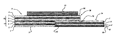
Figure 1 shows a first variant of the method according to the invention.
Figure 2 shows a second variant of the method.
b'igures 3 - 7 slww pos$ible assemblies of the laminate according to the
invention.
When producing a laminate, metal layers 1 - 4 alternating with fibre layers 5 -
7
impregnated with binder (prepreg) are stacked on top of one another in a
forming mould,
which is not shown in more detail, to give a stack 8. Tn the example shown the
Layers 5 - '~
each consist of two stacked impregnated fibre layers. It is possible to
incorporate one or
more impregnated fibre layers between two metal layers, as desired, This stack
has a region
9 with a Lower number of layers than the remainder of the laminate, as a
result of which a
step 10 is produced.
'This step is obtained because the series 11 consisting of the layers 1, 2, 5
and 6 has a
differerxt surface dimension to the series 12 consisting of the layers 3, 4
and 7.
When combining the layers 1 - 7 to give a whole, to produce a ~.nished
laminate, the
whole is subjected to an elevated pressure and temperature, As a supplementary
feature, the
pressure can be regularly distributed by the pressing tool 13 during this
operation. The
pressing tool 13 can be produced from laminate if a flat, single-curved or
double-curved
laminate is involved. The pressing tool 13 can be produced from metal strips
if a flat or
single-curved laminate is involved,
'With the aim of nevertheless achieving adequate application of pressure even
in the
protruding region 19 that has a smaller number of layers, the auxiliary tool
indicated in its
entirety by 14 is used. This auxiliary tool consists of layers 1', 2', 5' and
6' identical to the
first series 11. However, the auxiliary tool 14 is reversed, so that the fibre
layer 6
impregnated with binder does not adhere to the surface 1 s of the metal layer
3 during

CA 02476785 2004-08-06
heating and application of pressure, There is a layer 16 of release material
between the fibre
Iayer 6 impregnated. with binder and fibs mould.
The advantage of the use of an auxiliary tool 14 with the same mako-up as the
first
series 11 is that uniform application of pressure that is equal to the
pressure applies in the
complete laminate is nevertheless obtained even is the protruding region 19,
With this
arrangement the mechanical properties of the auxiliary tool 14 are the same ae
those of the
stack 11, so that as a result it is also not possible for any ices to arise.
'With the method according to the invention, the auxiliary tool 14 can be made
up
togother with the laminate. That is to say, at the start of the production
process the layers 1',
2', 5' and 5' of the auxiliary tool 14 do not yet have to be attached to one
another. 4n
application of pressure and heating, formation of the auytiliary tool 14 then
additionally
tales place automatically, assuming that this whole is covered by parts of the
laminate.
Flowever, an auxiliary tool 14 produced in this way can also be used in the
finisb~ed
state when fomniug the laminate, it is true that the auxiliary tool 14 is then
somewhat
thinner, because it has already been compressed and cured, but the thic~ess
thereof i9 thcn
correctly matched to the height of the step 10 in the laminate produced.
As shaven in Figuro 2, the pressing tool 1~ can also be applied do the
auxiliary tool 14
and the complete stacl~ 8, the battonn layer of the pressing tool 13 then
being separated
from the layer 6' of the auxiliary tool 14 and from the layer 1 of the stack 8
by a layer 16 of
release material.
Two possible assemblies of the laminate as discussed above are shown in
Figures 3
and 4. Ia Z~'igure 3 the series of protruding layers of both laminates lies
over the other series
11. The laminates ate attached to one another by meaiss of fixing mea~,s that
are inserted
through holes, the axes of which are indicated diagrammatically by 24.
In the variant in Figure 4 the series with protruding layers 12 are attached
to one
another.
In the variant in Figure 5 three di~'erent series 12, 12' arid 11 are provided
in each
lsnainate. The protruding series 12 of the one laminate lies over the series l
I of the other
laminate that proiru$es leask far, ett.
In the variant in Figure b, the series 12 that protrudes the furthest is
opposite the
series 11 of the other laminate, so that completely flat surfaces axe
obtained,
rn the variant in Figure 7 a laminate with two series 12, 11 is attached to a
laminate
with three series 11,12,12' so that only one side is flat,

Representative Drawing
A single figure which represents the drawing illustrating the invention.
Administrative Status

2024-08-01:As part of the Next Generation Patents (NGP) transition, the Canadian Patents Database (CPD) now contains a more detailed Event History, which replicates the Event Log of our new back-office solution.

Please note that "Inactive:" events refers to events no longer in use in our new back-office solution.

For a clearer understanding of the status of the application/patent presented on this page, the site Disclaimer , as well as the definitions for Patent , Event History , Maintenance Fee  and Payment History  should be consulted.

Event History

Description Date
Application Not Reinstated by Deadline 2011-08-08
Time Limit for Reversal Expired 2011-08-08
Inactive: IPC deactivated 2011-07-29
Deemed Abandoned - Failure to Respond to Maintenance Fee Notice 2010-08-06
Letter Sent 2009-08-26
All Requirements for Examination Determined Compliant 2009-07-13
Request for Examination Requirements Determined Compliant 2009-07-13
Request for Examination Received 2009-07-13
Inactive: IPC from MCD 2006-03-12
Inactive: First IPC derived 2006-03-12
Application Published (Open to Public Inspection) 2005-02-08
Inactive: Cover page published 2005-02-07
Letter Sent 2004-11-18
Inactive: Single transfer 2004-10-19
Inactive: First IPC assigned 2004-10-17
Inactive: IPC assigned 2004-10-17
Inactive: Courtesy letter - Evidence 2004-09-21
Inactive: Filing certificate - No RFE (English) 2004-09-16
Filing Requirements Determined Compliant 2004-09-16
Application Received - Regular National 2004-09-16

Abandonment History

Abandonment Date Reason Reinstatement Date
2010-08-06

Maintenance Fee

The last payment was received on 2009-07-30

Note : If the full payment has not been received on or before the date indicated, a further fee may be required which may be one of the following

  • the reinstatement fee;
  • the late payment fee; or
  • additional fee to reverse deemed expiry.

Please refer to the CIPO Patent Fees web page to see all current fee amounts.

Fee History

Fee Type Anniversary Year Due Date Paid Date
Application fee - standard 2004-08-06
Registration of a document 2004-10-19
MF (application, 2nd anniv.) - standard 02 2006-08-07 2006-07-25
MF (application, 3rd anniv.) - standard 03 2007-08-06 2007-07-19
MF (application, 4th anniv.) - standard 04 2008-08-06 2008-07-16
Request for examination - standard 2009-07-13
MF (application, 5th anniv.) - standard 05 2009-08-06 2009-07-30
Owners on Record

Note: Records showing the ownership history in alphabetical order.

Current Owners on Record
STORK FOKKER AESP B.V.
Past Owners on Record
ABDOEL FAZIEL RAJABALI
Past Owners that do not appear in the "Owners on Record" listing will appear in other documentation within the application.
Documents

To view selected files, please enter reCAPTCHA code :


To view images, click a link in the Document Description column. To download the documents, select one or more checkboxes in the first column and then click the "Download Selected in PDF format (Zip Archive)" or the "Download Selected as Single PDF" button.

List of published and non-published patent-specific documents on the CPD .

If you have any difficulty accessing content, you can call the Client Service Centre at 1-866-997-1936 or send them an e-mail at CIPO Client Service Centre.


Document
Description 
Date
(yyyy-mm-dd) 
Number of pages   Size of Image (KB) 
Description 2004-08-06 4 241
Abstract 2004-08-06 1 26
Claims 2004-08-06 3 111
Drawings 2004-08-06 2 75
Representative drawing 2005-01-13 1 20
Cover Page 2005-01-26 1 55
Filing Certificate (English) 2004-09-16 1 168
Courtesy - Certificate of registration (related document(s)) 2004-11-18 1 106
Reminder of maintenance fee due 2006-04-10 1 112
Reminder - Request for Examination 2009-04-07 1 122
Acknowledgement of Request for Examination 2009-08-26 1 188
Courtesy - Abandonment Letter (Maintenance Fee) 2010-10-04 1 172
Correspondence 2004-09-16 1 26
Fees 2006-07-25 1 36