Note: Descriptions are shown in the official language in which they were submitted.
CA 02476930 2004-08-19
WO 03/081055 PCT/GB02/05624
1
COMPONENT SUPPORT AND RADIOISOTOPE GENERATOR INCLUDING
ONE OR MORE COMPONENT SUPPORTS
The present invention relates to an interengaging component
support which is particularly, but not exclusively, suited to implementation
in a radioisotope generator of the type commonly used to generate
radioisotopes such as technetium-99m (99mTc).
The diagnosis and / or treatment of disease in nuclear
medicine constitute one of the major applications of short-lived
radioisotopes. It is estimated that in nuclear medicine over 90% of
io diagnostic procedures performed worldwide annually use 99mTc labelled
radio-pharmaceuticals. Given the short half-life of diagnostic radio-
pharmaceuticals, it is helpful to have the facility to generate suitable
radioisotopes on site. Accordingly, the adoption of portable hospital / clinic
size 99mTc generators has greatly increased over the years. Portable
radioisotope generators are used to obtain a shorter-lived daughter
radioisotope which is the product of radioactive decay of a longer-lived
parent radioisotope, usually adsorbed on a bed in an ion exchange column.
Conventionally, the radioisotope generator includes shielding around the
ion exchange column containing the parent radioisotope along with means
for eluting the daughter radioisotope from the column with an eluate, such
as saline solution. In use, the eluate is passed through the ion exchange
column and the daughter radioisotope is collected in solution with the
eluate, to be used as required.
CA 02476930 2004-08-19
WO 03/081055 PCT/GB02/05624
2
In the case of 99mTc, this radioisotope is the principle product
of the radioactive decay of 99Mo. Within the generator, conventionally the
99Mo is adsorbed on a bed of aluminium oxide and decays to generate
99mTc. As the 99mTc has a relatively short half-life it establishes a
transient
equilibrium within the ion exchange column after approximately twenty-four
hours. Accordingly, the 99mTc can be eluted daily from the ion exchange
column by flushing a solution of chloride ions, i.e. sterile saline solution
through the ion exchange column. This prompts an ion exchange reaction,
in which the chloride ions displace 99mTc but not 99Mo.
io In the case of radio-pharmaceuticals, it is highly desirable for
the radioisotope generation process to be performed under aseptic
conditions i.e. there should be no ingress of bacteria into the generator.
Moreover, due to the fact that the isotopes used and generated with the
generator are radioactive, and are thereby extremely hazardous if not
is handled in the correct manner, the radioisotope generation process also
should be conducted under radiologically safe conditions. Naturally, it is
desirable to ensure that when the elution process is performed, the
radiological safety of the generator is not compromised. In particular, when
the eluate is introduced into the generator, it is important for the
radiological
20 safety of the generator to be maintained.
In trying to ensure adequate radiological protection, some
known radioisotope generators have tended to be of a complicated
construction incorporating a large number of components. However, the
CA 02476930 2004-08-19
WO 03/081055 PCT/GB02/05624
3
radiological protection afforded by such structures can be compromised
where the interconnection of the various components is unreliable. Such
complex structures also add to the cost of the generator. It is thus
important that the actual construction of the generator is reliable and all
component interconnections are secured to a high degree of certainty.
United States Patent No. 3,946,238 describes a shielded
radioisotope generator comprising a cylindrical shielded housing for a
central repository. The repository is bound by a removable top cover and
side walls and a base which are made from lead and which act as the
1o shielding. Within the repository a bottle is located which contains an ion
exchange column in which 99Mo is absorbed. When it is desired to add
saline solution to the system to prompt the elution of 99mTc, the top cover is
removed, and the saline is introduced by way of a transfer pipette. The
saline solution is introduced by means of the pipette to an annular region
between the bottle and the inner surfaces of the shielding. From this
annular region the saline solution flows in a controlled manner into the
bottle containing the ion exchange bed via a series of radial openings in the
wall of the bottle. The transfer pipette has a long handle designed such
that a user's hands always remain outside the generator when saline is
introduced into the annular region about the bottle. It is apparent, however,
that the removal of the top cover for the purposes of introducing the saline
solution constitutes an unacceptable radiological risk as the interior of the
repository is radioactive.
CA 02476930 2004-08-19
WO 03/081055 PCT/GB02/05624
4
United States Patent No. 3,564,256 describes a radioisotope
generator having quick-coupling members for the elution process. The
generator includes a cylindrical holder containing a radioactive substance
bound to an ion exchange bed. The holder is closed by rubber plugs at
both ends, and is surrounded by shielding having passages opposite each
of the rubber plugs in which respective needles are located. At the
outermost ends of the needles quick-coupling members are provided to
enable a syringe vessel containing a saline solution to be quickly and easily
connected to one of the needles and to enable a collection vessel to be
1o connected to the other of the two needles. In use, each one of the rubber
plugs of the cylindrical holder is pierced by one of the needles to prompt
the elution of 99mTc from the ion exchange column. Suitable quick-coupling
members proposed in the document are conventional detachable injection
needle to injection syringe connections.
United States Patent No. 4,387,303 describes a radioisotope
generator comprising a column having an elute inlet aperture and an elute
outlet aperture and containing an ion exchange bed with the parent
radioisotope. Both the elute inlet and outlet are in communication with
channels in the surrounding shielding. One of the channels, that is in
communication with the elute outlet, is connected to a tapping point on the
generator via an eluate conduit. The tapping point is adapted to receive an
evacuated elution vial for collection of the daughter radioisotope in solution
and consists of a hollow needle that pierces the seal to the evacuated
CA 02476930 2004-08-19
WO 03/081055 PCT/GB02/05624
elution vial. The eluate conduit is also in communication with a source of
sterile air and the generator includes a device for interrupting the elution
process before the elution vial is filled by interrupting the flow of sterile
air.
No information is provided with regard to the construction of the generator
5 and in particular no information is provided as to how the hollow needle at
the tapping point is held in position.
The present invention seeks to provide a component support
that is simple in construction but provides greater reliability than existing
simple component supports and so is particularly suited for use in
io radioisotope generators where there exists a need for a radioisotope
generator that is simple in construction but which ensures the necessary
degree of sterility and radiological protection.
According to a first aspect of the present invention , there is
provided a component support for use in a radioisotope generator, the
component support comprising a latching member movable between an
engaging position and an open position characterised by further including a
bracing member mechanically associated with the latching member and
adapted to prevent movement of the latching member to the open position.
In a preferred embodiment of the present invention, the
component support may include a first plate on which the latching member
is mounted, with the first plate including an opening at or adjacent the
latching member for receiving the bracing member. The opening in the first
plate is preferably an aperture in the first plate adjacent the latching
CA 02476930 2004-08-19
WO 03/081055 PCT/GB02/05624
6
member on the side of the latching member facing the direction of
movement of the latching member from the engaging position to the open
position.
Preferably, the opening is of non-circular cross-section and
the bracing member has a corresponding non-circular cross-section. Also,
the latching member may additionally include a camming surface
engageable by the bracing member for urging the latching member away
from the open position.
More preferably the component support may also include a
io second plate on which the bracing member is mounted, the second plate
being arranged to lie substantially parallel to the first plate when the
bracing member is inserted through the opening in the first plate.
The latching member is preferably a generally L-shaped
structure consisting of a wall and a flange projecting therefrom, and in a
preferred embodiment the latching member also includes a second flange
arranged substantially parallel to the first flange for defining a slot
therebetween. It is envisaged but by no means essential that the
component support comprises at least two opposing latching members and
respective bracing members.
According to a second aspect of the present invention there is
provided a radioisotope generator having one or more component supports
as previously described. The latching member of the generator may be
mounted on a closure plate of the generator which include an opening for
CA 02476930 2010-01-26
29925-50
7
receiving the bracing member, and wherein the bracing member is
mounted on a cover plate of the generator such that insertion of the bracing
member into the opening mounts the cover plate over the closure plate.
Preferably, the radioisotope generator has two latching
s members mounted on the closure plate either side of a central component
aperture and wherein the cover plate also includes a component aperture
for alignment with the component aperture in the closure plate. The
radioisotope generator may also include a fluid port comprising a hollow
generally cylindrical body and a retaining plate, the hollow body being
io received in the component apertures in the closure plate and the cover
plate and the retaining plate being engaged by the opposed latching
members for securely holding the fluid port in position.
In the preferred embodiment, the radioisotope generator
includes a container consisting of a wall and a floor, with the opening to the
is container being closed by a closure plate. With this arrangement the
latching member is located on the container wall and the closure plate
includes a bracket for engagement with the latching member and an
opening at or adjacent the bracket and the bracing member is provided on
a cover plate such that insertion of the bracing member into the opening in
20 the closure plate aligns the bracing member with the latching member
thereby to prevent movement of the latching member to the open position.
CA 02476930 2010-01-26
29925-50
7a
According to another aspect of the present invention there is
provided a radioisotope generator including one or more component supports,
wherein each component support comprises a latching member and a first plate
on which said latching member is mounted, said latching member flexibly
moveable between an engaging position and an open position characterized in
that said first plate includes an opening at or adjacent the latching member
for
receiving a bracing member, wherein said bracing member is mounted on a
second plate, said second plate being arranged to lie substantially parallel
to said
first plate when said bracing member is inserted through said opening in said
first
plate, said bracing member being mechanically associated with the latching
member and adapted to prevent movement of the latching member to the flexed
open position.
An embodiment of the present invention will now be described, by
way of example only, with reference to the accompanying
CA 02476930 2004-08-19
WO 03/081055 PCT/GB02/05624
8
figures, in which:
Figure 1 illustrates a component support in accordance with
the present invention; and
Figure 2 illustrates a radioisotope generator incorporating
supports for tapping spikes in accordance with the present invention.
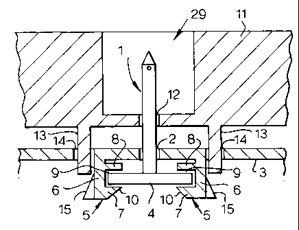
The component support is Illustrated generally by reference
numeral 29, and the component illustrated in Figure 1 is a spike 1 which
projects through an aperture 2 in a plate 3 and has a planar mounting
member 4 that is held in position by a pair of latching members 5. The
io latching members are movable between an engaging position in which they
engage the planar mounting member and an open position in which the
planar mounting member is not restrained by the latching members. Each
of the pair of latching members 5 includes a wall 6 projecting outwardly
from the surface of the plate 3 (downwardly as illustrated in Figures 1 and
2). The walls 6 are each spaced from the aperture 2 diametrically opposite
one another across the aperture 2. A flange 7 is provided at the free end of
each wall 6. The flanges 7 on each of the walls project away from the walls
towards one another and extend substantially parallel to the plate 3. A
second flange 8, substantially parallel to the first flange 7, is provided
between the first flange 7 and the plate 3. The first 7 and second 8 flanges
thus form a slot 9 suitable for receiving a planar member 4.
The plate 3 is preferably made from a hard plastics material
and the walls 6 and flanges 7, 8 are preferably moulded as a single unit
CA 02476930 2004-08-19
WO 03/081055 PCT/GB02/05624
9
with the plate 3. This results in the walls 6 and flanges 7, 8 having a small
degree of resiliency sufficient to be suitable for "snap-fit" engagement of a
planar member within the slot 9 defined by the first 7 and second 8 flanges.
For this reason, as illustrated in Figure 1, the first flange 7 has a camming
surface 10 facing away from the plate 3 for guiding and centering a planar
member 4 towards the slot 9 and for urging the small amount of flexure of
the opposed walls 6 necessary to permit the planar member 4 to pass the
periphery of the first flange 7 whereupon the walls 6 'snap' back into
position with the planar member 4 located and held in the slot 9 between
io the first and second flanges 7, 8.
Such a snap-fit connection is generally well-known and
provides a particularly quick method for securing two elements (in this case
the planar member 4 and the plate 3) together. However, the fact that this
manner of securement demands a small degree of flexure of the walls 6,
generally renders such a means of securement undesirable in
circumstances where the securement must be highly reliable. An external
force applied to the plate 3 is capable of causing flexure of the walls 6 to
the extent that the planar member 4 is accidentally freed from the slot 9.
For this reason, snap-fit connections have not been considered suitable in
the construction of radioisotope generators.
The component supports 29 illustrated in Figures 1 and 2
however provide a greatly improved reliability of securement over
convention snap-fit connectors, which renders the component supports 29
CA 02476930 2004-08-19
WO 03/081055 PCT/GB02/05624
particularly suited for use in radioisotope generators. The component
supports 29 include a cover 11 that is arranged to overlie the plate 3. The
cover 11 has a component aperture 12 for alignment with the aperture 2 in
the plate 3. The cover 11 also has a pair of bracing members 13 that
5 project (downwardly in Figures 1 and 2) away from the cover 11. Also,
adjacent each of the walls 6, on the opposite side of each of the walls 6 to
the flanges 7, 8, respective brace apertures 14 are provided in the plate 3.
The bracing members 13 on the cover 11 are positioned either side of the
component aperture 12 so as to be aligned with the brace apertures 14 in
io the plate 3. The brace apertures 14 are sized to permit the passage of the
bracing members 13 and preferably are non-circular in cross-section so
that the bracing member 13 is keyed into the brace aperture 14. With the
cover 11 positioned over the plate 3 and the bracing members 13 inserted
into the brace apertures 14, the bracing members 13 are mechanically
associated with the walls 6, and act as braces to the walls 6. This
substantially prevents outward flexure of the walls 6. In this way, the
reliability of the component support 29 is greatly enhanced.
In a particularly preferred embodiment, each associated wall
6 and bracing member 13 have co-operable camming surfaces and
followers. In Figure 1 the camming surface 15 is on the wall 6 facing
towards the bracing member 13. This enables the bracing member 13 to
actively engage with and urge the wall 6 inwardly towards the planar
member 4 when inserted in the slot 9 defined by the first and second
CA 02476930 2004-08-19
WO 03/081055 PCT/GB02/05624
11
flanges 7, 8. This further improves the reliability of the securement of the
component provided by the component supports 29.
Figure 2 illustrates an implementation of the component supports in
a radioisotope generator 16. The radioisotope generator 16 has an outer
container 17, a closure plate, referred to herein as a top plate 3 which is
sealingly secured to the outer container 17, and a separate top cover 11
which is secured to the outer container 17 over the top plate 3. Inside the
outer container 17 a radioactive shield 18 is located which is preferably, but
not exclusively, made from either lead or a depleted uranium core within a
io stainless steel shell. The radioactive shield 18 surrounds a tube 19
containing an ion exchange column 20. The ion exchange column 20
preferably consists of a mixture of aluminium and silica, onto which
molybdenum in the form of its radioactive isotope, 99Mo is adsorbed. The
tube 19 containing the ion exchange column 20 has frangible rubber seals
21 and 22 at opposing ends 23 and 24 which, as illustrated, when in use
are pierced by respective hollow needles 25 and 26.
Each of the hollow needles 25 and 26 are in fluid
communication with respective fluid conduits 27, 28 which in turn are in
respective fluid communication with an eluent inlet and an eluate outlet.
The fluid conduits 27, 28 are preferably flexible plastics tubing and in the
case of the tubing 27 that communicates with the hollow needle 25 at the
top 23 of the ion exchange column 20, the length of the tubing 27 is much
greater than the minimum required to connect the hollow needle 25 with
CA 02476930 2004-08-19
WO 03/081055 PCT/GB02/05624
12
the eluent inlet.
The top plate 3 of the radioisotope generator 16 has a pair of
apertures 2 through which the respective eluent inlet and eluate outlet
components project. The eluent inlet and eluate outlet components are
each hollow spikes I though in the case of the inlet component the hollow
spike additionally includes a filtered air inlet 30. The hollow spike 1
consists of an elongate generally cylindrical spike body 31 and an annular
retaining plate 32 which is attached to or is moulded as a single part with
one end of the spike body 31. The opposing end of the spike body 31 is
io shaped to a point and has an aperture 33 communicating with the interior
of the spike body 31 adjacent the point. This pointed end of the spike body
31 is shaped so that it is capable of piercing a sealing membrane of the
type commonly found with sample vials. The annular retaining plate 32
forms a skirt projecting outwardly from the spike body 31 and may be
continuous around the spike body 31 or discontinuous in the form of a
plurality of discrete projections.
The top cover 11 of the radioisotope generator 16 also
includes a pair of apertures 12 arranged so as to align with the apertures 2
in the top plate 3 and shaped to allow through passage of the spike body
31. Thus, each of the hollow spikes 1 is arranged to be held and supported
by its annular retaining plate 32 by latching members 5 located on the
inside of the top plate 3 whilst the hollow spike body 31 projects through
the apertures in both the top plate 3 and the top cover 11 to the exterior of
CA 02476930 2004-08-19
WO 03/081055 PCT/GB02/05624
13
the outer container 17. Each one of the apertures 12 in the top cover 11 is
located at the bottom of a well 34 that is shaped to receive and support
either an isotope collection vial 35 or a saline supply vial 36. Thus, both
vials 35, 36 are housed outside of the outer container 17 and are not
exposed to radiation from the ion exchange column 20.
The hollow spikes 1 are held in place by the component
supports 29 as described earlier with reference to Figure 1. Thus, the
spike body 31 projects through the aligned apertures in the top plate 3 and
the top cover 11 and is securely held in position by engagement of the
1o annular retaining plate 32 in the slot 9 defined by the first and second
flanges 7, 8 of the latching members 5. Retention of the plate 32 in the slot
9 is maintained by the supporting action of the bracing members 13 outside
of the walls 6 of the latching members 5 which substantially prevent
outward flexure of the walls 6.
is When the radioisotope generator 16 is constructed, the spike
body 31 is inserted through the aperture 2 in the top plate 3 and the
annular retaining plate 32 contacts the camming surfaces 10 on an
opposing pair of first flanges 7. Further pressure applied to the retaining
plate 32 forces outward flexure of the walls 6 supporting the first flanges 7
20 until the retaining plate 32 is able to pass the free end of the first
flanges 7.
Once the retaining plate 32 has passed the first flanges 7 the external
pressure on the walls 6 is eased and the walls 6 'snap' back to their normal
position locating the retaining plate 32 in the slots 9 defined by the first
and
CA 02476930 2004-08-19
WO 03/081055 PCT/GB02/05624
14
second flanges 7 and 8. The top cover 11 is then positioned over the top
plate 3 with the apertures 12 in the top cover 11 aligned with the spike
body 31 and the bracing members 13 aligned with apertures 2 in the top
plate 3 adjacent each of the walls 6. As the top cover 11 is brought into
contact with the top plate 3 the bracing members 13 pass through the
apertures 2 in the top plate 3 so as to be positioned next to, and preferably
in contact with, the outer surfaces of the walls 6. The interaction of the
bracing members 13 on the top cover 11 and the walls 6 of the top plate 3
thus provide reliable securement of the retaining plate 32 of the hollow
io spike 1 in the slot 9 defined by the first and second flanges 7, 8. The
tubing 27 and 28 is then fluidly attached to the hollow spikes 1 and the
outer container 17 is closed when the top plate 3 and the top cover 11 are
secured to the container.
When it is desired to attach a vial 35 or 36 to the hollow spike
1, a user positions the frangible seal of the vial over the pointed end of the
spike and pushes the vial down onto the spike 1. This causes the seal on
the vial 35 or 36 to be pierced establishing fluid communication between
the spike 1 and the vial. Once the seal has been pieced by the spike 1, the
vial is pushed down over the spike 1 until it rests and is supported by the
well 34 in the top cover 11.
In order to supply the ion exchange column 20 with the
chloride ions required for elution of the radioisotope, saline solution 37 is
drawn through the ion exchange column 20, by establishing a pressure
CA 02476930 2004-08-19
WO 03/081055 PCT/GB02/05624
differential across the ion exchange column 20. This is accomplished by
connecting the saline supply vial 36 to the eluent inlet which is in fluid
communication with the top end 23 of the ion exchange column 20 via the
tubing 27 and hollow needle 25 and connecting an evacuated collection
5 vial 35 to the eluate outlet which is in fluid communication with the bottom
end 24 of the ion exchange column 20 via the tubing 28 and hollow needle
26. The pressure differential is established by virtue of the fluid pressure
of
the saline in the supply vial 36 and the extremely low pressure in the
evacuated collection vial 35. This urges passage of the saline solution 37
io through the ion exchange column 20 to the collection vial 35 carrying with
it
the daughter radioisotope.
The component support is simple in design but by the
interaction of the bracing member on one plate with the wall of the snap-fit
component on the other plate and highly reliable component support is
15 provided. Although reference has been made in the description to a
component support suitable for a hollow spike, it will be apparent that the
component support of the present invention may be employed with
alternative components that are intended to be secured in a snap-fit holder.
For example, the component support may be used as a
means for attaching the top plate to the outer container of the radioisotope
generator. With this arrangement, latching members are attached to the
inner side walls of the outer container. Each latching member is spaced
from the wall of the outer container by means of a bridge element so as to
CA 02476930 2004-08-19
WO 03/081055 PCT/GB02/05624
16
define a bracket receiving region between the latching member and the
wall of the container. Thus, the wall of the latching member is arranged
substantially parallel to the container wall and the slot defined by the
paired
flanges mounted on the wall of the latching member lies substantially
perpendicular to the container wall. This arrangement also requires the top
plate to have an equivalent number of brackets for location and
engagement with respective latching members. Thus, as the top plate is
lowered into position, the bracket attached to the periphery of the top plate
and projecting downwardly therefrom, engages the first of the flanges on
io the latching member. The bracket urges the latching member to flex away
from the container wall thereby enlarging the bracket receiving region until
the bracket is capable of passing the periphery of the flange whereupon the
latching member snaps back into position trapping part of the bracket in the
slot defined by the two flanges. As described previously, the bracing
is member projects from the top cover and is locatable in an aperture in the
top plate, such that, as before, it is mechanically associated with the
latching member and acts to brace the latching member against flexure.
It is not a requirement of the present invention that the
bracing means is locatable through an aperture in the top plate such that it
20 acts as an exterior abutment to the component support wall. For example,
it is alternatively envisaged that the component support wall may include a
blind bore, into which the bracing means is inserted, to provide the desired
improved support for the latching member.
CA 02476930 2004-08-19
WO 03/081055 PCT/GB02/05624
17
Moreover, it is not a requirement of the present invention that
the plates of the component support contain apertures through which the
component passes. Instead, the component may extend away from the
surface of the first plate bearing the walls of the component support (in the
illustrated embodiment the top plate 3) in which case the second plate (in
the illustrated embodiment the top cover 11) need only align the bracing
members with the brace apertures in the first plate. Furthermore, although
paired flanges defining a slot are illustrated above, it will be appreciated
that the slot may be defined between a single flange and the surface of the
io first plate. Further and alternative features of the component support are
envisaged without departing from the scope of the present invention as
claimed.