Language selection

Search

Patent 2477137 Summary

Third-party information liability

Some of the information on this Web page has been provided by external sources. The Government of Canada is not responsible for the accuracy, reliability or currency of the information supplied by external sources. Users wishing to rely upon this information should consult directly with the source of the information. Content provided by external sources is not subject to official languages, privacy and accessibility requirements.

Claims and Abstract availability

Any discrepancies in the text and image of the Claims and Abstract are due to differing posting times. Text of the Claims and Abstract are posted:

  • At the time the application is open to public inspection;
  • At the time of issue of the patent (grant).
(12) Patent: (11) CA 2477137
(54) English Title: APPARATUS FOR MACHINING A HUB BEARING UNIT FOR A WHEEL OF A MOTOR VEHICLE
(54) French Title: APPAREIL D'USINAGE D'UNE UNITE DE ROULEMENTS DE MOYEU DESTINEE A UNE ROUE D'UN VEHICULE A MOTEUR
Status: Expired and beyond the Period of Reversal
Bibliographic Data
(51) International Patent Classification (IPC):
  • B23B 05/02 (2006.01)
  • B23B 05/04 (2006.01)
  • B23Q 41/00 (2006.01)
(72) Inventors :
  • CALDANA, MARCUS (Italy)
(73) Owners :
  • MINGANTI INTERNATIONAL LIMITED
(71) Applicants :
  • MINGANTI INTERNATIONAL LIMITED (Ireland)
(74) Agent: MARKS & CLERK
(74) Associate agent:
(45) Issued: 2010-05-11
(86) PCT Filing Date: 2003-06-20
(87) Open to Public Inspection: 2004-01-08
Examination requested: 2008-04-01
Availability of licence: N/A
Dedicated to the Public: N/A
(25) Language of filing: English

Patent Cooperation Treaty (PCT): Yes
(86) PCT Filing Number: PCT/EP2003/006554
(87) International Publication Number: EP2003006554
(85) National Entry: 2004-08-20

(30) Application Priority Data:
Application No. Country/Territory Date
BO2002A000409 (Italy) 2002-06-27

Abstracts

English Abstract


The presser (7, 107) for the axial pre-loading of the internal crowns (4) of
the bearings, is co-axially inserted in the driver (9), with possibility of
relative movement with respect to the same driver. The internal crown of the
bearing which is resting on the flat reference surface (106) co-operates with
a centring pin (306) which may be provided with movable and active members
(10) useful for the same centring.


French Abstract

L'invention concerne une presseuse (7, 107) destinée au pré-chargement axial des couronnes internes (4) des roulements et étant introduite de manière coaxiale dans l'entraînement (9), un déplacement relatif par rapport à l'entraînement étant possible. La couronne interne du roulement reposant sur la surface de référence plate (106) coopère avec une broche centrale (306) pouvant être équipée d'éléments mobiles et actifs (10) utiles pour le centrage.

Claims

Note: Claims are shown in the official language in which they were submitted.

CLAIMS
1) Apparatus for the reduction of the runout in the disk carrying flange (101)
of
the box (1) with internal bearings (3, 4) for the hub of the wheels of the
motor
vehicles, of the type comprising means for the axial pre-loading the internal
crowns
(4) of the bearings in such a manner that the workpiece is machined in the
same
conditions in which the same will be in the utilization phase, characterised
by the fact
that the axial pre-loading means (7, 107) of the internal crowns of the
bearings are
connected to the driver (9) for the driving in rotation of the box (1) with
the flange
(101) to be machined, while the internal crown (4) of the bearings which is
opposed
to the one directly interested by said pre-loading means, frontally rests on a
surface
(106) which is perpendicular to the same pre-loading means and means are
provided
to ensure a correct axial alignment of the workpiece with respect to said
axial pre-
loading means, with respect to said rest surface (106) and with respect of
said driving
means (9).
2) Apparatus according to claim 1), in which the pre-loading means (7, 107)
are co-axially arranged inside of the driver (9) which in correct phase
engages one
end of the box (1) of the workpiece to be machined, to avoid the same to
rotate or to
drive in rotation around its axis.
3) Apparatus according to claim 1, in which means are provided to allow that
the pre-loading means (7, 107) are relatively movable and independent with,
respect
to the driver (9), both in the axial direction, and in rotation around the
common axis,
the said pre-loading means or at least their head (107) in contact with the
workpiece
to be machined, freely rotatable around their axis.
4) Apparatus according to claim 1) in which the centring means comprise a pin
(306) arranged perpendicularly on the resting surface (106) of one of the
internal
crowns (4) of the bearings of the workpiece to be machined and such pin
internally
engages said crown (4) of the bearings in order to realize the required
centring of the
same workpieces with regard to the various operative components of the
apparatus.
5) Apparatus according to claim 4) in which said pin (306) is provided with a
head flaring which facilitates the coupling with the internal crown of the
bearings.
6

6) Apparatus according to claim 4), in which said pin (306) is such to engage
with precision the internal crown (4) of the bearings.
7) Apparatus according to claim 4), in which said pin (306) is such to engage
with clearance the internal crown (4) of the bearings and is laterally
provided with
means (10) with radial and self centring expansion and retraction movement,
which
usually are in the retracted rest position and that once the pin is inserted
in the
workpiece, are carried in expansion to contact the internal crown (4) of the
bearings
and to centre in correct manner the same workpiece, while leaving it free in
the axial
movement with respect to the pre-loading means (7, 107).
8) Apparatus according to claim 4, in which the flat surface (106) for the
resting of the workpiece, with the relative pin (306) for the centring of the
same
workpiece, are connected to a mandrel (206) which may be fixed or upon command
may rotate around its axis with under control of speed and phase control
means.
9) Apparatus according to claim 1, in which means are provided in order to
allow that the unit formed by the driver (9) and by the pre-loading pusher (7,
107)
can, if required, act also as gripper for the manipulation of the workpiece
for example
for the discharge of the machined workpiece from the positioning station (6).
10) Apparatus according to claim 9, in which the positioning station (6) for
the
workpiece to be machined is arranged with its axis vertically and is oriented
upwardly
and all the operative members of the same apparatus are arranged with the axis
vertically oriented, the unit formed by the driver (9) and by the pre-loading
pusher (7,
107), assembled on a movable slide on orthogonal axis, which may carry other
operative members, such for example the feelers for the runout of the
workpiece,
while the tool (2) is mounted on another slide movable on orthogonal axis,
which can
carry aboard the loading and unloading grippers of the workpieces to be
machined
and already machined.
7

Description

Note: Descriptions are shown in the official language in which they were submitted.


CA 02477137 2004-08-20
WO 2004/002660 PCT/EP2003/006554
APPARATUS FOR MACHINING A HUB BEARING UNIT FOR A WHEEL OF A MOTOR VEHICLE
DESCRIPTION
The invention finds industrial utilisation in the machine tools for the
working on
industrial scale of the units with bearings and with flange suitable to carry
the disk of
the brakes for the hubs of the wheels of the motor vehicles, to effect the
precision
machining the surface of said flange, with the object of reducing the effects
of the so-
called runout or wobble caused by the small working and assembling tolerances
of
the bearings and of the other portions of the unit which is referred to. This
technology
is for example described in the patent applications PCT/US00/14187 (TIMKEN)
and
PCT/EP00111684 (SKF). Both these patent applications are focused to effect the
machining for the above mentioned purposes, of a unit made by a box suitable
to be
fixed to the frame or the steering portions of the motor vehicle and in which
there is
axially assembled in a rotatable manner with the interposition of bearings, a
hub
which is axially hollow for the possible connection to a rotation shaft and
which is
provided at one end with a flange which carries perpendicularly projecting
screw
studs which pass through corresponding holes of the braking disk which is then
fixed
on this flange with screws, while the said screw studs are then used to fix to
the hub,
with suitable screw nuts, the rim of the wheel of the motor vehicle. The above
mentioned patent applications, provide to keep steady the external box of the
unit, to
cause the hub to rotate around its axis by charging it axially and finally to
machine
with the machine tool the surface in view of the flange of the hub on which
there will
be assembled the disk of the brakes.
Only in the patent application PCT/EP00/11684 (SKF) there has been
provided that said working method may be applied also to unit of boxes with
bearings
for the hubs of the wheels of the motor vehicles, different from these above
mentioned and substantially of the type indicated by reference P schematically
shown in the Figure 1 of the attached drawings, which comprise a box 1 which
is
integrally carrying the flange 101 to be machined on the visible face with the
tool 2
and which with its lateral and internal surface forms the external crown for
the rolling
i

CA 02477137 2004-08-20
WO 2004/002660 PCT/EP2003/006554
means 3 of the bearings, which co-operate with internal crowns 4 reciprocally
connected with elastic means 5. To effect the machining of workpieces P of
this kind,
in the SKF patent application it is provided that, as shown in Figure 1, one
of the
internal crowns 4 of the bearings is resting with its external end on the flat
and
horizontal surface 106 of the unit 6, on which the whole of the same internal
crowns 4
is secured and axially pre-loaded by means of a pin 7 which axially passes
through
with clearance said crowns 4 and which with its head 107 rests on the external
end of
the crown 4 opposed to the one resting on the surface 106. The pin 7 is
axially pulled
in the direction indicated by the arrow 8, in such a manner to pre-load the
internal
crowns of the bearings substantially with the same entity of pre-load which is
given to
same during the assembling phase of the workpiece on the hub of the wheel, in
such
a manner that the same workpiece results to be substantially machined in the
same
conditions in which it is during the utilization phase. The box is then
carried in
rotation by the known driver 9, while its flange 101 is machined by the tool
2. The
solution shown in Figure 1 has resulted to be not usable in the industrial
scale, for the
difficulty of positioning of the pin 7 and of the workpiece on the supporting
structure
and for the difficulty to axially align the same workpiece with good precision
with
respect to the whole structure for supporting and driving in rotation. The
main object
of the invention is the realisation of an apparatus which can ensure rapidity,
precision
and complete automation in the work positioning of the said workpieces P
having the
flanged box and with internal bearing for the hubs of the motor vehicles.
According to
the invention, the pin 7 is overturned and is co-axially inserted in the
driver 9 with
possibility of relative movement with respect to the same driver. The internal
crown of
the bearing which is resting on the reference flat surface co-operates with a
centring
pin which ,may be provided with movable and active members for the same
centring.
Further features of the invention, and the advantages deriving therefrom, will
appear better evident from the following description of a preferred embodiment
of
same made, by way of non-limiting example, with reference to the figures of
single
attached sheet of drawing, in which, in addition to the already considered
Figure 1, it
is noted that Figures 2 and 3 show with the same outline of Figure 1, with
portions in
2

CA 02477137 2004-08-20
WO 2004/002660 PCT/EP2003/006554
section and with other portions in view, the apparatus which is referred to in
two
following steps of its working cycle.
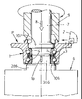
From Figure 2 it is noted that the frontal and visible surface on the lower
ring 4
of the inner bearings of the workpiece P, rests on the flat and horizontal
surface 106
of a vertical mandrel 206 of the station 6 which in the machine tool provides
to the
right positioning of the said workpiece with respect to the several operating
members
of the apparatus which is referred to. The mandrel 206 is provided with a
cylindrical
and coaxial pin 306 which axially engages, completely or partially, at least
the lower
ring 4 of the bearings of the workpiece or which engages also a portion of the
upper
crown of the same bearings and this pin may have a diameter which may co-
operate
with the crown/crowns 4 with sufficient precision, or may co-operate with
clearance
with said crowns 4, in which case the pin 306 may be provided with lateral
devices 10
radially movable with self centring movement, which may be activated to ensure
a
precise axial alignment of the workpiece upon the mandrel 206. When the
workpiece
P is assembled upon the mandrel, the means 10 are initially in the back
position and
only in a second time they are activated in order to align the same workpiece
with
precision on the mandrel. The action of the means 10 on the crown 4 of the
bearing
is soft in order to not cause deformations and to allow to the workpiece the
whole
required axial displacement freedom for the phases of axial pre-charging
(further
described) of the bearings. Usefully, the front in view of the pin 306 is
tapered in
order to favour the automatic placing of the workpiece on the mandrel 206 by
means
of manipulating grippers of the machine, connected for example to the slide
movable
on orthogonal axis, which carries the working tool 2. The mandrel 206 may be a
fixed
apparatus, as provided in the patents mentioned in the introduction, or may an
apparatus which upon command may rotate around its axis with the control of
speed
and phase regulation means.
Always from Figure 2 it is noted that once the workpiece P is placed in the
station 6, there intervenes the second slide with orthogonal movements of the
machine, upon which there is assembled the driver 9 which according to the
invention is axially hollow and carries internally a rod 7 with a lower head
107 having
3

CA 02477137 2004-08-20
WO 2004/002660 PCT/EP2003/006554
a diameter which is smaller than the one of the axial cavity of the box 1 of
the
workpiece P. The portions 7 and 9 are reciprocally uncoupled both in the axial
movements and in the rotatory movements and are controlled by own means, not
shown because easily conceivable and realisable by persons skilled in the art.
The
rod 7 is, at the beginning, extended from the driver 9 with its head 107, in
such a
manner to be lowered with this inside the box 1 and to be brought to rest with
the
same head on the upper crown 4 of the bearings of the workpiece P, to subject
the
bearings to an axial pre-loading which is proportionate to the one of the
utilization
conditions of the workpiece. In a following phase the driver 9 is lowered on
the box 1
in such a manner to frontally engage it on the internal or on the external
diameter, as
shown for example in Figure 3. The driver 9 is connected to rotation and stop
means,
while the rod 7 or at least its head 107 is preferably freely rotatable around
its axis.
Once the axial pre-loading of the internal crowns 4 and of the bearings by
means of the presser 7, 107 is effected, the driver 9 can rotate the box 1
with the
relative flange 101 for the working by the tool 2, while the mandrel 206
remains
motionless, or preventively the driver 9 may be held motionless and the
mandrel 206
may be rotated together with the internal crowns 4 of the bearings, while the
surface
to be machined of the flange 101 is controlled by a feeler placed for example
on the
same slide which carries the unit 9, 7, 107 and which detects the features of
the
runout, to correctly control the following working phases of the same flange
by the
tool 2. The working of the flange 101 may be performed with the mandrel 206
stopped in any angular position or prearranged angular position related to the
features of the detected runout, or the same mandrel may rotate around its
axis with
a correct relative motion with respect to the external box 1. Once the working
phase
of the flange 101 is finished, the above mentioned operation for the measuring
of the
runout may be performed again for control purpose.
Once the working phase of the flange 101 is finished, the driver 9 is axially
moved away form the workpiece P, then is moved away the presser 7, 107, and
then
the possible centring means 10 of the pin 306 are neutralised and the machined
workpiece in moved away by means of the grippers of the working machine (not
4

CA 02477137 2004-08-20
WO 2004/002660 PCT/EP2003/006554
shown). It is to be understood that if it is imposed by particular conditions,
the unit 9,
7, 107 may be. pre-arranged with clamping means to act also like a gripper,
for
example for the discharging from the station 6 of the machined workpiece while
in
this one there is positioned by other means a following workpiece P to be
machined.
s

Representative Drawing
A single figure which represents the drawing illustrating the invention.
Administrative Status

2024-08-01:As part of the Next Generation Patents (NGP) transition, the Canadian Patents Database (CPD) now contains a more detailed Event History, which replicates the Event Log of our new back-office solution.

Please note that "Inactive:" events refers to events no longer in use in our new back-office solution.

For a clearer understanding of the status of the application/patent presented on this page, the site Disclaimer , as well as the definitions for Patent , Event History , Maintenance Fee  and Payment History  should be consulted.

Event History

Description Date
Time Limit for Reversal Expired 2013-06-20
Letter Sent 2012-06-20
Grant by Issuance 2010-05-11
Inactive: Cover page published 2010-05-10
Inactive: Final fee received 2010-02-23
Pre-grant 2010-02-23
Notice of Allowance is Issued 2009-11-09
Letter Sent 2009-11-09
Notice of Allowance is Issued 2009-11-09
Inactive: Approved for allowance (AFA) 2009-11-04
Letter Sent 2008-05-20
Request for Examination Requirements Determined Compliant 2008-04-01
All Requirements for Examination Determined Compliant 2008-04-01
Request for Examination Received 2008-04-01
Inactive: IPC from MCD 2006-03-12
Inactive: Cover page published 2004-10-25
Inactive: Notice - National entry - No RFE 2004-10-21
Letter Sent 2004-10-21
Application Received - PCT 2004-09-21
National Entry Requirements Determined Compliant 2004-08-20
Application Published (Open to Public Inspection) 2004-01-08

Abandonment History

There is no abandonment history.

Maintenance Fee

The last payment was received on 2009-05-22

Note : If the full payment has not been received on or before the date indicated, a further fee may be required which may be one of the following

  • the reinstatement fee;
  • the late payment fee; or
  • additional fee to reverse deemed expiry.

Patent fees are adjusted on the 1st of January every year. The amounts above are the current amounts if received by December 31 of the current year.
Please refer to the CIPO Patent Fees web page to see all current fee amounts.

Owners on Record

Note: Records showing the ownership history in alphabetical order.

Current Owners on Record
MINGANTI INTERNATIONAL LIMITED
Past Owners on Record
MARCUS CALDANA
Past Owners that do not appear in the "Owners on Record" listing will appear in other documentation within the application.
Documents

To view selected files, please enter reCAPTCHA code :


To view images, click a link in the Document Description column. To download the documents, select one or more checkboxes in the first column and then click the "Download Selected in PDF format (Zip Archive)" or the "Download Selected as Single PDF" button.

List of published and non-published patent-specific documents on the CPD .

If you have any difficulty accessing content, you can call the Client Service Centre at 1-866-997-1936 or send them an e-mail at CIPO Client Service Centre.


Document
Description 
Date
(yyyy-mm-dd) 
Number of pages   Size of Image (KB) 
Description 2004-08-19 5 253
Abstract 2004-08-19 2 63
Drawings 2004-08-19 1 33
Claims 2004-08-19 2 109
Representative drawing 2004-08-19 1 12
Representative drawing 2010-04-15 1 10
Notice of National Entry 2004-10-20 1 201
Courtesy - Certificate of registration (related document(s)) 2004-10-20 1 128
Reminder - Request for Examination 2008-02-20 1 119
Acknowledgement of Request for Examination 2008-05-19 1 189
Commissioner's Notice - Application Found Allowable 2009-11-08 1 163
Maintenance Fee Notice 2012-07-31 1 170
PCT 2004-08-19 2 76
Correspondence 2010-02-22 1 30