Note: Descriptions are shown in the official language in which they were submitted.
CA 02477186 2008-02-27
1. Title of Invention
Tong Jaw and a Method for Constructing the Tong Jaw
II. Background of the Invention
A. Field of Invention
The present invention relates to pipe tongs or power tongs used in the oil and
gas
industry to make-up and break-out sections of drill pipe and other tubular
members having
threaded connections. More particularly, the present invention relates to a
jaw for use in
such tongs and a method for constructing the jaw.
B. Description of Related Art
Power tongs are often employed in the oil and gas industry to break-out or
make-
up threaded connections on tubular members (such as drill pipe, tubing, or
casing). It is
generally required that one tong grip and rotate one section of a tubular
string and a
second tong grip and hold stationary the other section of the tubular string.
The first tong
rotating the first tubular member is typically referred to as the power tong,
while the
second tong holding the second tubular member stationary is typically referred
to as the
back-up tong. Examples of conventional power tongs can be seen in references
such as
U.S. Pat. Nos. 5,671,961, 5,702,139, and 5,819,604 to Buck.
Power tongs ordinarily have two or more jaws which are actuated to grip and
release the tubular member. The actual contact with the tubular is typically
accomplished
through the use of die inserts which are removably positioned in the power
tong jaws. Die
inserts are commonly held in place through a dovetail key arrangement or other
groove
and spline configurations as seen in U.S. Patent No. 4,576,067 to Buck.
Power tong jaws are commonly machined from solid pieces of metal bar stock, or
semi-finished casting or from ring forgings which are rolled to near final
dimensions and
then machined to final dimensions. An example of jaws 1 constructed in this
manner is
1
CA 02477186 2008-02-27
seen in Figure 1. It can be seen that the jaw 1 includes a jaw body 4 with
dovetail slots 3
formed therein. The rear portion of the jaw body 4 includes a jaw roller 5
secured to the
jaw body 4 by a roller pin 6. A number of machine hours on lathes, mills, and
saws are
required to construct these jaws 1 from the preliminary material. A portion of
these hours
are spent forming the complex dovetail slot 3 in the jaw 1, which dovetail
slot 3 receives
the die insert 2. The process of forming jaws from solid material in this
manner is costly
and time consuming.
Jaws are often formed from multiple pieces for applications where the weight
of a
completely solid jaw might be excessive. An example of such jaws 106 is seen
in Figure 2.
Lower and upper plates 100 and 102 are cut, e.g., using a laser, waterjet, or
torch.
Afterward, the plates 100 and 102 must be machined or milled before they are
connected
to a jaw mid-section 101 using bolts 105. Like the solid jaws 1 discussed
above, the jaw
mid-section 101 is cut from metal bar stock or ring forging and machined.
Although the
jaw mid-section 101 is smaller in diameter than the solid jaw 1(and,
therefore, involves
less material), like the solid jaw 1, the jaw mid-section 101 contains
dovetail slots 104 for
receiving die inserts 103. As noted above, substantial machine work is
required to form
these dovetail slots 104. Thus, the process of constructing jaws in this
manner is less
expensive than constructing jaws out of solid material, but this manner of
constructing
jaws is still costly-primarily because of the machine work that must be done
on the jaw
mid-section 101, especially the complex machine work required to form the
dovetail slots
104. What is needed in the art is a power tong jaw design which may be
manufactured
less expensively, from less preliminary material, and requires less machine
work.
III. Brief Summary of the Invention
The present invention provides a jaw for use in power tongs and a method for
constructing the jaw.
2
CA 02477186 2008-02-27
According to one aspect of the present invention there is provided a power
tong
jaw comprising: a. an upper plate and a lower plate; and b. at least three
column members
positioned between said upper plate and said lower plate, at least two of said
column
members having die insert grooves formed therein.
According to a further aspect of the present invention there is provided a
method
for constructing a power tong jaw comprising the steps of: a. providing a
substantially flat
upper plate and a substantially flat lower plate; b. providing at least one
substantially
elongated column member having a die insert groove formed therein; c.
providing at least
one substantially elongated column member not having one of said die insert
grooves
formed therein; and d. connecting said upper plate to said lower plate with
said column
members.
According to another aspect of the present invention there is provided a
method for
constructing a power tong jaw comprising: a. providing a substantially flat
upper plate and
a substantially flat lower plate; b. providing at least two separately formed
substantially
elongated column members, at least one of said column members having a die
insert
groove formed therein; and c. connecting said upper plate to said lower plate
using said
column members.
According to a still further aspect of the present invention there is provided
a
power tong jaw comprising: a. an upper plate and a lower plate; and b. at
least two
separate means for connecting said upper plate to said lower plate, said at
least two means
for connecting said upper plate to said lower plate being positioned between
said upper
plate and said lower plate, at least one of said means for connecting said
upper plate to
said lower plate comprising means for gripping a tubular member.
3
CA 02477186 2008-02-27
IV. Brief Description of the Several Views of the Drawings
Figure 1 is an exploded view of a prior art power tong jaw constructed from
solid
metal.
Figure 2 is an exploded view of a prior art power tong jaw constructed from
multiple pieces.
Figure 3 is an exploded view of a power tong jaw constructed using the method
of
the present invention.
Figure 4 is a close-up view of a column member having a die insert groove
formed
therein.
Figure 5 is an assembled view of a power tong jaw constructed using the method
of
the present invention.
Figure 6 is an exploded view of a power tong jaw member constructed using the
method of the present invention.
Figure 7 is an assembled view of a power tong jaw member constructed using the
method of the present invention.
Figure 8 is a perspective view of a back-up power tong incorporating a jaw
member of the present invention.
V. Detailed Description of the Invention
The following detailed description refers to the accompanying figures.
The term "power tong" as used herein refers to both power tongs for rotating
tubular members and back-up power tongs for holding tubular members stationary
against
rotation.
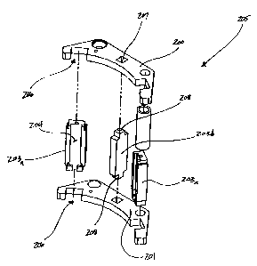
In a preferred embodiment, the invention provides a pivoting power tong jaw as
seen in Figures 3 and 5. The jaw 205 comprises an upper plate 200, a lower
plate 201, and
three column members 203. The upper plate 200 and lower plate 201 are arranged
4
CA 02477186 2008-02-27
horizontally, the former above the latter. The upper plate 200 and the lower
plate 201
each contain two column member slots 206 and one column member opening 207. In
a
preferred embodiment, the upper and lower plates will be formed by a high
speed,
precision cutting process. Examples of high speed precision cutting processes
would
include laser cutting or water jet cutting, shear or punch press types of
heavy metal
fabrication techniques, and may include plasma torch cutting. Plasma torch
cutting and
flame torch cutting would generally not be considered precision cutting
processes, and
conventional milling would not be considered high speed, although these
methods could
be used in less preferred embodiments for producing the plates, as could
casting processes.
As illustrated in Figures 3 and 5, each of the colunm members 203 is
positioned vertically.
Two of the column members 203a have die insert grooves 204 formed in them for
receiving dies. (A close-up view of a column member 203a is depicted in figure
4, which
clearly shows the die insert groove 204.) As seen in Figures 3 and 5, the two
column
members 203a having the die insert grooves 204 are positioned between the
upper plate
200 and lower plate 201 such that each end of each of these column members
203a fits
into a corresponding column member slot 206. The column members 203 are welded
into
place, or secured by another common method (e.g., using bolts or screws). The
third
column member 203b is also positioned between the upper plate 200 and the
lower plate
201. This column member 203b does not have a die insert groove 204 and has
points 208
at each end which extend through the column member openings 207 in the upper
plate 200
and lower plate 201, thereby stabilizing the column member 203b.
As seen in Figures 3 and 5, the jaw insert 101 (depicted in Figure 2) is not
present
in this embodiment of the present invention. Thus, this design greatly reduces
the amount
of material and machining required to produce the jaw. Additionally, the
column
members can be formed by a more economical method than machining, such as
CA 02477186 2008-02-27
investment casting. Thus, a large number of identical colunm members could be
produced
for use in constructing the tong jaws of the present invention. Because the
column
members contain the complex detail required to retain the dovetail die
inserts, the casting
further reduces the amount of machining required to produce each tong jaw.
Moreover,
the same column members may be used on a variety of different jaw sizes (i.e.,
jaws
designed to grip different diameter tubulars). To produce different sized
jaws, it is only
necessary to modify the top and bottom plates. Thus, one benefit of this
design is that a
jaw for an usual diameter tubular may be manufactured very quickly by cutting
the correct
size top and bottom plates and assembling them with pre-manufactured column
members,
which would be the same size regardless of the top and bottom plate
dimensions. This
method can reduce the time necessary to produce a nonstandard sized jaw from
days to
hours. This method is also far more economical than prior art methods,
allowing jaws of
the present invention to be produced at approximately 77% of the material and
production
cost of prior art jaws.
In another embodiment, the invention provides a power tong jaw member as seen
in Figures 6 and 7. The jaw member 301 comprises an upper plate 304, a lower
plate 305,
and four column members 302. The upper plate 304 and lower plate 305 are
arranged
horizontally, the former above the latter. The upper plate 304 and lower plate
305 contain
colunm member slots 306. The column members 302 are connected to the upper
plate 304
and lower plate 305 at the column member slots 306. Two of the colunm members
302a
have die insert grooves 303 for retaining die inserts 307. As illustrated in
Figure 7, the
column members 302a having die insert grooves 303 are positioned such that the
die
inserts 307 face inwardly in an arcuate orientation corresponding to the
curvature of the
particular diameter tubular being gripped, thereby allowing both of the die
inserts 307 to
come into contact with the surface of a tubular when the power tong jaw member
301 is in
6
CA 02477186 2008-02-27
use. The column members 302b which do not have die insert grooves 303 are
positioned
parallel to each other on opposite sides of the upper plate 304 and lower
plate 305.
The power tong jaw member seen in Figures 6 and 7 could be used in a sliding
jaw
adaptor for pivoting jaw power tongs as seen in U.S. Patent Serial No.
6,619,160. The jaw
members of the present invention could replace the sliding solid jaw members
seen
therein.
This embodiment of the present invention could also be used to replace the
solid
arcuate jaw members found in back-up power tongs known in the art, for
example, the
back-up power tongs shown in U.S. Patent No. 5,702,139 to Buck, which is
incorporated
herein by reference in its entirety. A back-up power tong design incorporating
power tong
jaw members according to the present invention is illustrated in Figure 8.
Figure 8 shows
a back-up power tong 402 a having power tong jaw member 401 mounted on an
outside
jaw assembly 404 and an inside jaw assembly 403. As shown in Figure 8, this
jaw
member is similar to that seen in Figures 6 and 7, however, there are no
column members
on the side of this embodiment of the jaw member. As discussed in U.S. Patent
No.
5,702,139 to Buck, when actuated, the outside jaw assembly 404 and inside jaw
assembly
403 of the back-up power tong shown in Figure 8 lock together around a tubular
(not
shown). A cylinder assembly 405 having an arcuate jaw member 407 is extended
toward
the jaw members 401 so that the arcuate jaw member 407 engages the tubular.
The
contact between the arcuate jaw member 407 and the tubular brings the tubular
into
contact with the die inserts 406 on the jaw members 401, which, in cooperation
with the
arcuate jaw member 407, grip the tubular. A polyurethane cylindrical spring
408 is used
to hold the jaw member 407 in the proper position for the initial bite, but
allows the jaw
member 407 to move to accommodate undersized tubulars or to compensate when
subjected to high torques. While only one spring 408 is shown in contact with
each of the
7
CA 02477186 2008-02-27
jaw members 401 in Figure 8, it will be understood a second spring 408 is
located on the
other side of jaw 401, but is hidden from view. The springs 408 are composed
of
relatively rigid elastic material and are secured by being positioned between
the jaw
member 401 and bolts 500 (or bolts 501 for the spring hidden from view). The
springs
408 could be secured by other means known in the art, e.g., it could be
secured by pins
running through the jaw assembly and the spring. While the pivoting jaw
embodiment of
the present invention offers the greatest cost savings, the sliding jaw
adapter embodiment
and the back-up power tong embodiment also offer significant savings over
earlier power
tong jaw designs known in the art.
While many parts of the present invention have been described in terms of
specific
embodiments, it is anticipated that still further alterations and
modifications thereof will
no doubt become apparent to those skilled in the art. For example, other
designs besides a
dovetail slot might be used to retain die inserts, or the number of column
members having
die insert grooves could be altered. Other embodiments are possible and
modifications
may be made to the embodiments without departing from the spirit and scope of
the
invention. The preceding detailed description is not meant to limit the
invention. Rather,
the scope of the invention is defined by the appended claims. It is therefore
intended that
the following claims be interpreted as covering all such alterations and
modifications as
fall within the true spirit and scope of the invention.
8