Note: Descriptions are shown in the official language in which they were submitted.
CA 02477653 2004-08-30
WO 03/080163 PCT/US02/32264
1
PUNCTURING MEANS FOR USE IN AN INHALATION DEVICE
Background of the Invention
Field of the Inventiofa
The present invention relates generally to facilitating release of powder
contained
in a receptacle. More specifically, the present invention relates to the
administration of
medication by a method and apparatus for facilitating inhalation of powder
medicaments.
Related Art
In the medical field, it is often desirable to administer various forms of
medication
to patients. Well known methods of introducing medication into the human body
include
the oral ingestion of capsules and tablets, intravenous injection through
hypodermic
needles, and numerous others. In one method, certain medications may be
inhaled into a
patient's respiratory tract and lungs through the nose or mouth. Certain of
these
medications, such as bronchodilators, corticosteroids, etc., for the treatment
of asthma
and other respiratory anomalies, may be aimed at the respiratory tract
directly. Others are
inhaled for purposes of systemic treatment, i.e. for treatment of any area of
the body
through absorption from the respiratory tract through the lung tissue, into
the deep lungs,
and into the bloodstream. Each of these medications comes in a variety of
forms,
including fluids, which are commonly administered as an aerosol vapor or mist,
as well
as solids. Inhalable solids typically take the form of fine, dry powders.
Specialized
devices, such as inhalers, are provided to assist the patient in directing
these fine powder
medications into the respiratory tract.
Various types of inhalers are known for the administration of dry powder
medicaments. However, each of these inhalers suffers certain drawbacks. For
example,
U.S. Patent No. 5,787,881 discloses an inhaler that is used with encapsulated
dry powder
medicaments. However, use of this device requires numerous steps and imposes a
number of inconveniences on a user. For example, the medication capsules used
with the
device have an aperture formed therein prior to insertion into an opening in
the inhaler.
Therefore, there exists a danger that an amount of medication may be lost
prior to or
during insertion into the device. After insertion of the capsule, use of the
device requires
the additional step.that a cover must be closed before the medication may be
inhaled.
CA 02477653 2004-08-30
WO 03/080163 PCT/US02/32264
2
Inhalation devices configured for use with a capsule containing some type of
medicament are shown in U.S. Patent No. 4,069,819 to Valentini et al. ("the
'819
patent") and U.S. Patent No. 4,995,385 to Valentini et al. ("the '385
patent"). The
inhalation device described in the '385 patent was developed to overcome the
drawbacks
of the device described in the '819 patent. Particularly, in a large number of
cases, the
device described in the '819 patent experienced irregular and incomplete
emptying of the
capsule, thereby resulting in difficulties in properly administering the
medicament in the
capsule. The inhalation device described in the '385 patent attempts to
overcome this
deficiency by tapering the nebulization chamber toward the end surface that
comprises
the discharge holes. Thus, the nebulization chamber of the '385 patent is not
cylindrical,
but rather frusto-conical in form in an attempt to achieve regular complete
emptying of
the nebulization chamber.
However, further improvements in the design of inhalation devices are needed
to
achieve high emitted doses and highly dispersed powders while maintaining low
resistance, especially when the inhaler is used with high doses and is
operated at low
peak inspiratory flow rates (PIFR) and low inhalation volumes. As used herein,
"emitted
dose" (ED) refers to the percentage of the dose of powder medicament that is
emitted
from a receptacle in the inhalation device. The dispersal of the powder can be
quantified
by measuring the volume mean geometric diameter (VMGD) of the emitted powder.
As
used herein "volume mean geometric diameter" refers to the average geometric
diameter
of the powder. As used herein, "resistance" refers to the square root of the
pressure
gradient across the inhaler divided by the peak inspiratory flow rate through
the inhaler.
As used herein "low peak inspiratory flow rate" refers to a peak inspiratory
flow rate of
approximately 25 L/min or less. Moreover, improvements are needed to achieve
high
emitted doses and highly dispersed powders that are consistently reproducible,
i.e., that
have a low standard deviation of emitted dose percentage and VMGD,
respectively.
Another drawback of the inhalation devices described in the '819 and the '385
patents is the piercing device that is used to puncture the capsule. Such
conventional
piercing devices are formed from circular stock, with the points created by
pinching the
stock at an angle, thereby creating a single sharp cutting edge. Drawbacks of
such a
design are that the point (which must puncture the capsule material) is often
rounded,
CA 02477653 2004-08-30
WO 03/080163 PCT/US02/32264
3
lessening its effectiveness as a piercing device. Moreover, burrs often form
on the lower
edge, which can stop the piercing device from retracting from the capsule,
thereby
causing a device failure. The holes formed by such a conventional piercing
device are
generally round, and do not have the appearance of being cut by a sharp edge.
With such
a conventional design, the capsule is often crushed, rather than punctured or
pierced. If
such a conventional piercing device is used with brittle capsule materials
such as gelatin,
pieces of capsule material of a size that can be inhaled are usually broken
off from the
capsule. Thus, conventional piercing devices are less than optimal,
particularly for brittle
capsule material.
Another drawback of conventional inhalation devices is that they have no means
for indicating when the powder in the inhaler is ready for inhalation by the
user. It is
desirable to have a means for indicating to the user that a dose of powder is
ready for
inhalation. For example, it would be desirable for a patient using a device,
for dispensing
fluticasone propionate (used to treat asthma) to know when the device is ready
for
inhalation.
Thus, there is a need in the art for an improved method and apparatus for
inhalation of dry powder medicaments. What is needed is an inhaler that
provides for a
higher emitted dose that is consistently reproducible with low standard
deviation. Such a
need is particularly acute for low peak inspiratory flow rates, and for high
dosage ranges.
There is a further need in the art for an improved means for puncturing the
capsule
containing the medicament. The present invention, the description of which is
fully set
forth below, solves the need in the art for such improved methods and
apparatus.
Summary of the Invention
The present invention relates to a method and apparatus for facilitating
release of
powder from a device. In one aspect of the invention, a device for emitting
powder is
provided. The device includes a first casing portion, and a second casing
portion
removably coupled to the first casing portion. A cylindrical chamber, defined
by a
straight wall of circular cross section, is coupled to the first casing
portion. The chamber
has a proximal end and a distal end. A ring is circumferentially coupled to an
inner
surface of the chamber. The ring is preferably disposed at approximately a
midpoint of
I =
CA 02477653 2004-08-30
WO 03/080163 PCT/US02/32264
4
the chamber, or, alternatively, disposed adjacent the proximal end of the
chamber. The
second casing portion includes an emitter portion disposed at the proximal end
of the
chamber when the first and second casing portions are coupled together. The
emitter
portion defines at least one aperture configured to emit powder therethrough.
In another aspect of the present invention, the device is configured as an
inhalation device for administering powder. In this aspect of the present
invention, the
emitter portion is configured as an inhalation portion so that powder is
dispersed in the
chamber and administered to a user through the inhalation portion. The
inhalation
portion may be configured as a mouth piece for inhalation through the mouth,
or as a
nose piece for inhalation through the nose.
One aspect of the invention comprises an optimized configuration of a device
for
administering powder that comprises a chamber defined by a wall and configured
to hold
a receptacle containing a powder, the wall defining a plurality of vents, and
the inhalation
device further comprising an inhalation portion defuzing at least one aperture
for emitting
powder therethrough. The inhalation device is configured to have a resistance
of at most
0.28 (cm H20)112 /L/min and to provide an emitted dose of at least 85% when
the dose of
powder is up to 20 mg and when the device is operated at a peak inspiratory
flow rate of
L/min or less and at an inhalation volume of 0.75 L or less. Preferably the
standard
deviation of the emitted dose is 10% or less.
20 In another aspect, the device of the present invention is configured to
cause the
emitted powder to be highly dispersed. By "highly dispersed" is meant that the
VMGD
of the emitted powder is substantially similar to the VMGD of the powder
contained in
the receptacle. Highly dispersible powders have a low tendency to agglomerate,
aggregate or clump together and/or, if agglomerated, aggregated or clumped
together, are
25 easily dispersed or de-agglomerated as they emit from an inhaler and are
breathed in by
the subject. Typically, the highly dispersible particles suitable in the
methods of the
invention display very low aggregation compared to standard micronized powders
which
have similar aerodynamic diameters and which are suitable for delivery to the
pulmonary
system. Properties that enhance dispersibility include, for example, particle
charge,
CA 02477653 2004-08-30
WO 03/080163 PCT/US02/32264
surface roughness, surface chemistry, relatively large geometric diameters,
and the
configuration of the device used to dispense the powder.
In another aspect of the invention, the powder is contained in a receptacle
that is
disposed in the chamber. Upon puncturing the receptacle, powder is dispersed
in the
5 chamber and emitted or inhaled from the device.
In yet another aspect of the present invention, the device of the present
invention
includes means for puncturing the receptacle. In one embodiment, the means for
puncturing can be configured as a staple. Such a staple is preferably
configured in a
substantially U-shape, having two prongs. In one aspect of the present
invention, each of
the prongs has a square cross-section. In another aspect of the preseiit
invention, the
substantially U-shaped staple includes a rounded portion and two prongs that
define a
non-planar inner edge and a non-planar outer edge of the staple, the staple
being formed
from' a rectangular length having two end surfaces and four planar side
surfaces that
intersect to form four non-planar edges. The inner edge of the staple is
configured to be
one of the non-planar edges, and the outer edge of the staple is the non-
planar edge that is
opposite that non-planar edge. Each end surface is an angled diamond-shaped
surface.
In a preferred aspect, each end surface has a top point at an apex of the
inner edge, and a
bottom point at an apex of the outer edge, each top point forming a cutting
point for one
of the prongs.
In another embodiment, the puncturing means can be configured as a
substantially
longitudinal prong comprising a puncturing surface on the distal end of the
prong, a
primary cutting surface running from the proximal end to the distal end of the
prong and
terminating at the puncturing surface, and a substantially planar face
opposite to the
primary cutting edge and running from the proximal end to the distal end of
the prong.
Another embodiment of the puncturing means comprises a substantially
longitudinal
prong comprising a puncturing surface on the distal end, a primary cutting
surface
terminating at the puncturing surface, and a face opposite to the primary
cutting edge,
wherein the prong is configured to create an opening in a wall by forming a
hanging chad
in the wall, the hanging chad having a free end formed by the puncturing
surface and the
primary cutting edge and a hinge coupled to the wall formed by the face. In
another
CA 02477653 2004-08-30
WO 03/080163 PCT/US02/32264
6
embodiment, the prong is configured to form a hanging chad in a wall of the
receptacle
having a longitudinal axis substantially parallel to the prong and a minor
axis
substantially perpendicular to the longitudinal axis, the hanging chad being
opened to an
angle of at least 30 to 45 degrees with respect to the minor axis of the
receptacle. In
another embodiment the prong is configured so that at least 3/4 of the length
of the prong
can be inserted into a receptacle without breaking off chads in the
receptacle.
In each of these embodiments, the prong preferably has an angled surface at
the
distal end, the surface having a distal end terminating at the puncturing
surface and a
proximal end terminating at the substantially planar face. In addition, the
prong
preferably is tapered, so that its distal end is smaller than its proximal
end, to facilitate
removing the prong from the receptacle. The prong also preferably has a
plurality of
longitudinal faces and a plurality of longitudinal edges running from the
proximal end to
the distal end of the prong. In one embodiment, the cross section of the prong
is a
pentagon. In a related embodiment, the width of the substantially planar face
may be
very small and the four longitudinal faces may be substantially at right
angles to each
other so that the prong has substantially a diamond shaped cross section. In
another
embodiment, the cross section of the prong is a triangle.
In another embodiment of the invention, the puncturing means comprises one or
more of the longitudinal prongs coupled to a base, preferably in a U-shape. In
another
aspect of the invention, any of these embodiments of the longitudinal prongs
may be
coupled to the device for administering powder.
In still a further aspect of the present invention, a method for dispensing
powder
by inhalation is provided. Such a method comprises
providing a powder inhalation device, the device comprising
a first casing portion,
a cylindrical chamber, defined by a straight wall of circular cross-
section, coupled to said first casing portion, said chamber having a proximal
end and a
CA 02477653 2004-08-30 =
WO 03/080163 PCT/US02/32264
7
distal end and configured to receive a receptacle therein, said chamber
comprising a ring
circumferentially coupled to an inner surface of said chamber, and
a second casing portion removably coupled to said first casing
portion, said second casing portion comprising an inhalation portion disposed
at the
proximal end of said chamber when said first and said second casing portions
are
coupled, said inhalation portion comprising a hemispheric region defining a
plurality of
apertures configured to emit powder therethrough;
puncturing the receptacle to allow release of powder into said chamber;
and
dispersing powder through inhalation of the powder through said
inhalation portion.
In one aspect of the present invention, the inhaling step is carried out by
inhaling
the powder through a mouthpiece into a user's mouth. Alternatively, the
inhaling step
may be carried out by inhaling the powder through a nose piece into a user's
nose.
The present invention also encompasses an indicating device comprising a body
disposed within a casing and reversibly moveable between a first and a second
position,
an indicator moveable between a rest position and an indicating position, and
a means for
coupling the body and the indicator, wherein upon a first movement of the body
from the
first position to the second position, the means for coupling couples the body
and the
indicator, and upon a second movement of the body from the second position to
the first
position, the indicator moves from the rest position to the indicating
position.
In another embodiment, the present invention encompasses an indicating device
comprising a body disposed within a casing and reversibly moveable between a
first
position and a second position, an indicator reversibly moveable between a
rest position
and an indicating position, a lip coupled to the indicator and a flange
coupled to the body
for engaging the lip, wherein upon a first movement of the body from the first
position to
the second position, the flange engages the lip, and upon a second movement of
the body
CA 02477653 2004-08-30
WO 03/080163 PCT/US02/32264
8
from the second position to the first position, the engagement of the lip and
the flange
causes the indicator to move from the rest position to the indicating
position.
The invention further encompasses one of the previously described embodiments
of a device for emitting powder comprising a means for indicating readiness of
the device
for emitting powder. The means for indicating readiness of the device for
emitting
powder may comprise one of the previously described embodiments of an
indicating
device.
In addition, the invention comprises a method for indicating the readiness of
a
device for emitting a medicament. Such a method comprises
providing a device for dispensing a medicament, the device comprising a
casing comprising at least one aperture configured to emit powder
therethrough, a body
coupled to said casing and reversibly moveable between a first position and a
second
position, and an indicator coupled to said casing and reversibly moveable
between a rest
position and an indicating position;
applying an axial force to said body to move said body from said first
position to said second position, which readies the powder for dispensing and
couples
said body to said indicator;
releasing said axial force from said body to allow said body to move from
said second position to said first position, which moves said indicator to
said indicating
position; and
dispensing the medicament from said device.
The invention further comprises a method for indicating that a device for
dispensing a medicament has been used. Such a method comprises
providing a device for dispensing a medicament, the device comprising a
casing comprising at least one aperture configured to emit a medicament
therethrough, a
body coupled to said casing and reversibly moveable between a first position
and a
CA 02477653 2007-03-27
77223-31
9
second position, and an indicator coupled to said casing and
reversibly moveable between a rest position and an
indicating position;
applying an axial force to said body to move said
body from said first position to said second position, which
couples said body to said indicator;
dispensing the medicament from the device;
releasing said axial force from said body to allow
said body to move from said second position to said first
position, which moves said indicator to said indicating
position to indicate that the device has been used.
Another aspect of the invention provides a
puncturing device for puncturing a powder capsule suitable
for use with an inhaler, comprising: a longitudinal prong
comprising a distal end, a proximal end, and a periphery; a
sharp puncturing point, disposed on the distal end of the
prong, wherein the sharp puncturing point makes the initial
puncture in the powder capsule; a primary cutting edge
disposed on the periphery of the prong, running from the
proximal end of the prong to the distal end of the prong,
and terminating at the sharp puncturing point; and a planar
face disposed on the periphery of the prong opposite of the
primary cutting edge and running from the proximal end of
the prong to the distal end of the prong.
Features and Advantages
One feature of the present invention is that it
provides, in a low resistance inhaler with a highly
dispersed powder, high emitted doses that are consistently
reproducible over a range of peak inspiratory flow rates,
inhalation volumes and dosage quantities.
CA 02477653 2007-03-27
77223-31
9a
Advantageously, the present invention improves and optimizes the emitted dose
at low
peak inspiratory flow rates, low inhalation volumes, and high dose ranges. A
particularly
advantageous feature of the present invention is its ability to operate at low
peak
inspiratory flow rates, such as would be associated with a child, an elderly
person, or a
person with a respiratory disease, such as chronic obstructive pulmonary
disease (COPD).
One advantage of the present invention is that the means for puncturing used
in
the device is less expensive to manufacture than conventional piercing
devices.
Advantages of the injection molding manufacturing process used for the
puncturing
means include reliability, reproducibility, and design flexibility, such as
the ability to
make a wide variety of shapes and sizes of longitudinal prongs. For example,
larger
longitudinal prongs of the present invention can create larger openings in the
receptacles
than conventional piercing devices, which allows for higher emitted doses at
low peak
inspiratory flow rates, low volumes, and high dosage quantities. Another
advantage of
the present invention is that at least one configuration of the puncturing
means facilitates
forming a hanging chad in the wall of the receptacle, with an opening of at
least 30 to 45
degrees, to facilitate more efficient removal of powder from the receptacle
and, thus,
higher emitted doses than could be achieved with conventional piercing
devices.
i CA 02477653 2004-08-30 =
WO 03/080163 PCT/US02/32264
Moreover, the means for puncturing of the present invention advaintageously
provides
improved puncturing performance since less force is needed to puncture the
receptacles,
and fewer failures result than with conventional piercing devices. Yet another
advantage
is that the prongs are shaped for easy removal from the receptacle without
breaking off
5 the hanging chad formed in the wall of the receptacle.
Another advantage of the preferred means for puncturing is an improvement to
the emitted dose rate of the inhaler. In one aspect of the invention, the
puncturing means
improves the powder flow from the receptacle by increasing the size of the
holes in the
receptacle. In another aspect of the invention, the puncturing means improves
the peak
10 inspiratory flow rate by opening a hanging chad in the wall of the
receptacle to an angle
of at least 30 to 45 degrees with respect to the wall of the receptacle. Con-
sequently, the
emitted dose of the powdered medicament delivered to a patient will be
independent of
how fast the patient breathes, thereby ensuring that a consistent dose of
medicament is
delivered each time. Another advantageous feature of the present invention is
the
accuracy of medicament dosage delivered thereby. Since only one dosage of
medication
is present in the inhaler during each use, the possibility of overdose is
eliminated, and the
medicament need not be metered prior to delivery. A patient may simply inhale
all
medicament present in the device. Yet another advantage is the design of the
puncturing
means allows for a greater range of puncturing depths without breaking off the
chads
formed in the receptacle, allowing for greater optimization of the inhaler.
Because the present invention operates only under the inhalative power of the
patient, the inhaler carries the additional advantage that no accessory
device, such as a
compressed air cylinder or other propellant, needs to be used in conjunction
with the
present invention.
Another advantage of the present invention is that during inhalation, the
medicament is subjected to mixing in the dispersion chamber. This helps to
ensure that
the medicament exiting the inhaler and entering the patient's respiratory
system is in the
form of a fine dry powder, facilitating medicament deposition in the lungs. In
addition,
inhalation of finer powders is typically more comfortable for the patient.
0 CA 02477653 2004-08-30 0
-- -- - - - -
WO 03/080163 PCT/US02/32264
11
Still another advantage of the present invention is that it can be used with
individuals who cannot breathe hard, such as a child, an elderly person, or a
person
suffering from a respiratory disease, such as asthma, or individuals who are
sleeping or in
a coma.
Yet another advantage of the apparatus of the present invention is that it is
reusable. To reuse, a patient removes the emptied receptacle, and replaces it
with a fresh
receptacle filled with the proper dose of medicament.
Another advantage of the present invention is that it includes a means for
indicating when a device for emitting powder is ready for inhalation. Such a
means for
indicating informs the user when the device is ready for use and/or when tlie
device needs
to be refilled or discarded. For example, the means for indicating could be
used with a
device for emitting fluticasone propionate (used to treat asthma) to indicate
that the
device is ready for inhalation. Alternatively, the means for indicating could
be used with
an epinephrine pen for treating allergies to indicate that the pen has been
used. In
addition, the means for indicating preferably makes an audible click so that a
user will
know when the device has been properly actuated. Also, the means for
indicating is easy
to manufacture and use.
Brief Description of the Figures
The present invention is described with reference to the accompanying
drawings.
In the drawings, like reference numbers indicate identical or functionally
similar
elements.
FIG. 1 is a front view of one embodiment of a device of the present invention;
FIG. 2 is a cross-section of the device shown in FIG. 1 along line 2-2;
FIG. 3 is an enlarged partial cross-section of one embodiment of a dispersion
chamber of the present invention;
CA 02477653 2004-08-30
WO 03/080163 PCT/US02/32264
12
FIG. 4 is an enlarged partial cross-section of another embodiment of a
dispersion
chamber of the present invention showing one location for a ring in the
dispersion
chamber;
FIG. 5 is an enlarged partial cross-section of another embodiment of a
dispersion
chamber of the present invention showing another location for a ring in the
dispersion
chamber;
FIG. 6 is an enlarged partial cross-section of another embodiment of a
dispersion
chamber of the present invention showing another location for a ring in the
dispersion
chamber;
FIG. 7A is a top view of a preferred embodiment of a staple suitable for use
with
the device of the present invention;
FIG. 7B is a front view of the embodiment shown in FIG. 7A;
FIG. 7C is a side view of the embodiment shown in FIG. 7A;
FIG. 7D is an isometric view of the embodiment shown in FIG. 7A;
FIG. 8 shows the puncture obtained with the staple shown in FIGS. 7A through
7D;
FIG. 9A shows a partial view of another embodiment of a staple suitable for
use
with the device of the present invention;
FIG. 9B illustrates the puncture obtained with the staple shown in FIG. 9A;
FIG. 10 is a bar graph illustrating emitted dose at peak inspiratory flow
rates of
20 L/min (left bar), 40 L/min (center bar), and 60 L/min (right bar) for four
dispersion
chamber configurations;
1 l1
CA 02477653 2004-08-30
_... __... .. ,,
WO 03/080163 PCT/US02/32264
13
FIG. 11 is a bar graph illustrating emitted dose at low peak inspiratory flow
rates
for devices with varying numbers of vents;
FIG. 12 is a bar graph showing a comparison of mass fraction distributions
obtained for 6 mg (left bar) and 50 mg (right bar) fill weights;
FIG. 13 is a graph showing glucose levels (mg/dL) in beagle dogs after
administration of insulin using an aerosol generator and a device of the
present invention
with the low ring configuration substantially as shown in FIG. 4;
FIG. 14 is a bar graph illustrating the percentage emitted dose as a function
of air.
volume; and
FIG. 15 is an exploded cross-sectional view of an alternate embodiment of a
device of the present invention.
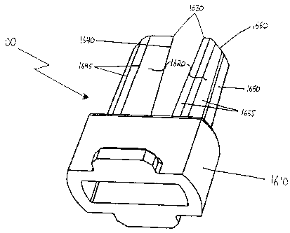
FIG. 16A is a perspective view of an alternative embodiment of a puncturing
device suitable for use with the present invention.
FIG. 16B is a front view of the puncturing device shown in FIG. 16A.
FIG. 16C is a side view of the puncturing device shown in FIG. 16A.
FIG. 16D is a top view of the puncturing device shown iri FIG. 16A.
FIGS. 17A-17C are schematic diagrams of one of the prongs of the puncturing
device shown in FIGS. 16A-D being used to puncture a receptacle and create a
hanging
chad therein.
FIG. 18 is a front cross-sectional view of an alternative embodiment of the
device
for administering powder comprising a means for indicating the readiness of
the device.
FIGS. 19A-19C are enlarged partial cross-sectional views of a preferred
embodiment of the means for indicating readiness of the device.
CA 02477653 2004-08-30
~ ..... _._--
WO 03/080163 PCT/US02/32264
14
Detailed Description of the Preferred Embodiments
Overview
The present invention provides an improved method and apparatus for
facilitating
release of powder. In a preferred embodiment, the powder is contained in a
receptacle.
As used herein, the term "receptacle" includes but is not limited to, for
example, a
capsule, blister, film covered container well, chamber, and other suitable
means of storing
a powder known to those skilled in the art. The present invention will be
described below
in the context of a method and apparatus for dispensing dry powder medicaments
for
inhalation by a patient. However, it should be apparent to one skilled in the
art that the
invention is not limited to such an exemplary embodiment, and could be used
for other
purposes.
As will be described in more detail below, an apparatus of the present
invention is
an inhaler that includes a chamber. In one embodiment, the chamber is
configured to
receive the receptacle containing the medicament. To improve the emptying of
the
receptacle and provide a higher reproducible emitted dose, the chamber
includes a ring
circumferentially coupled to an inner surface of the chamber. The ring is
preferably
disposed at approximately a midpoint of the chamber, or alternatively,
adjacent the
proximal end of the chamber. In proper use, air will exit the inhaler carrying
a full dose
of medicament in the form of a fine, dry powder.
Another aspect of the present invention is an optimized chamber configured to
have a resistance of at most 0.28 (cm H20) 112 /L/min and to provide an
emitted dose of at
least 85% when the dose of powder is up to 20 mg and when the device is
operated at a
peak inspiratory flow rate of 25 L/min or less and at an inhalation volume of
0.75 L or
less.
The inhaler of the present invention is preferably configured with a means for
puncturing the receptacle that improves puncturing performance, particularly
with brittle
receptacle material. In one preferred embodiment, the means for puncturing the
receptacle of the present invention is configured as a substantially U-shaped
staple with
two prongs, each prong having a sharp point and two cutting edges. In one such
embodiment, each prong has a square cross-section, with the staple material
being bent
CA 02477653 2004-08-30 =
WO 03/080163 PCT/US02/32264
around a face so that the innermost part of the U-shaped staple is flat. In
another such
embodiment, the staple material is rotated 45 degrees so that it is bent
around an edge so
that the innermost part of the U-shaped staple is an edge. In such an
embodiment, the end
surface of each prong is an angled diamond-shaped surface.
5 In another preferred embodiment, the means for puncturing the receptacle is
configured as a substantially longitudinal prong comprising a puncturing
surface on the
distal end, a primary cutting surface running from the proximal end to the
distal end of
the prong and terminating at the puncturing surface, and a substantially
planar face
opposite to the primary cutting edge and running from the proximal end to the
distal end
10 of the prong. The prong preferably has an angled surface at the distal end,
the angled
surface having a distal end terminating at the puncturing surface and.
aproximal end
terminating at the substantially planar face. In addition, the prong is
preferably tapered
so that the distal end is smaller than the proximal end, to facilitate
removing the prong
from a receptacle. The prong also preferably has a plurality of longitudinal
faces and a
15 plurality of longitudinal edges running from the proximal end to the distal
end of the
prong.
The prong is configured to create an opening in a wall by forming a hanging
chad
in the wall, the hanging chad having a free end formed by the puncturing
surface and the
primary cutting edge and a hinge coupled to the wall formed by the face. In a
preferred
embodiment, the prong is configured to open the hanging chad to an angle of at
least 30
to 45 degrees between the minor axis of the receptacle and the hanging chad,
wherein the
minor axis is substantially perpendicular to a longitudinal axis of the
receptacle, which is
substantially parallel to the longitudinal prong.
The methods of the present invention use an inhaler to dispense powder by
inhalation. As will be discussed in greater detail below, a user operates the
device to
puncture the receptacle to disperse powder in the chamber, and inhales the
powder
through the inhalation portion. The present invention further encompasses a
means for
indicating readiness coupled to a device for administering powder.
CA 02477653 2004-08-30
WO 03/080163 PCT/US02/32264
16
Inhaler and Associated Method of the Present Invention
A front view of one embodiment of an inhalation device 100 of the present
invention is shown in FIG. 1. The rear view of device 100 is substantially
identical to the
front view. Device 100 includes a first or lower casing portion 120 and a
second or upper
casing portion 130 removably coupled to first casing portion 120. Upper casing
portion
130 and lower casing portion 120 include a flattened region 132 and 122,
respectively,
for ease of gripping the casing for use by a patient. Lower casing portion 120
preferably
includes an outer casing 126 and an inner casing 124 movably received within
outer
casing 126. A removable cap 110 is provided at the user or inhalation end of
the device.
Preferred materials for device 100 include Food and Drug Administration (FDA)
approved, USP tested plastics. Preferably, device 100 is manufactured u~ing an
injection
molding process, the details of which would be readily apparent to one skilled
in the art.
FIG. 2 is a cross-section of device 100 shown in FIG. 1 along line 2-2. As
shown
in FIG. 2, device 100 includes an inhalation or emitter portion 220.
Inhalation portion
220 comprises a hemispheric region 222 that defines a plurality of apertures
224. It
should be understood that the present invention is not limited to a particular
number of
apertures 224, and can be configured such that at least one aperture 224 is
provided. An
inhalation piece 226 is provided to allow for inhalation of the medicament by
a user.
Inhalation piece 226 can be configured as a mouth piece for inhalation through
a user's
mouth. Alternatively, inhalation piece 226 can be configured as a nose piece
for
inhalation through a user's nose.
Device 100 includes a cylindrical chamber 210 that is defined by a straight
wall
212 of circular cross-section. Chamber 210 has a proximal end 214 and a distal
end 216.
A plurality of vents 218 are defined by wall 212, and are configured for
introducing air
into chamber 210 to disperse powder released from a capsule 219. It should be
understood that the present invention is not limited to a particular number of
vents 218,
and can be configured such that at least one vent 218 is provided. Powder
released from
capsule 219 is dispersed in chamber 210 and inhaled through apertures 224 and
inhalation
piece 226 by the user.
i I
CA 02477653 2007-03-27
77223-31
17
In other embodiments of the invention, receptacles other than capsules are
used,
such as blisters and film covered container wells as is known in the art. In
one
embodiment, the volume of the receptacle is at least about 0.37 cm3. In
another
embodiment, the volume of the receptacle is at least about 0.48 cm3 . In yet
another
embodiment, the receptacles have a volume of at least about 0.67 cm3 or 0.95
cm3 . In
one embodiment of the invention, the receptacle is a capsule designated with a
capsule
size 2, 1, 0, 00, or 000. Suitable capsules can be obtained, for example, from
Shionogi
(Rockville, MD). Blisters can be obtained, for example, from Hueck Foils,
(Wall, NJ).
The receptacle encloses or stores particles, also referred to herein as
powders.
The receptacle is filled with particles in a manner known to one skilled in
the art. For
example, vacuum filling or tamping techinologies may be used. Generally,
filling the
receptacle. with powder can be carried out by methods known in the art. In one
embodiment of the invention, the particle or powder enclosed or stored in the
receptacle
have a mass of at least about 5 milligrams (mg). In another embodiment, the
mass of the
particles stored or enclosed in the receptacle is at least about 10 mg, and up
to
approximately 50 mg. In a preferred embodiment, the mass of the particles is
approximately 20 mg.
In one embodiment of the present invention, particles used with the device
have a
tap density of less than about 0.4 g/ cm3. Particles having a tap density of
less than about
0.4 g/ cm3 are referred to herein as "aerodynamically light". In a preferred
embodiment,
the particles have a tap density of near to or less than about 0.1 g/ em3. Tap
density is a
measure of the envelope mass density characterizing a particle. The envelope
mass
density of particles of a statistically isotropic shape is defined as the mass
of the particle
divided by the minimum sphere envelope volume within which it can be enclosed.
Features that can contribute to low tap density include irregular surface
texture and
hollow or porous structure. Particularly preferred particles and powders are
described in
U.S. Patent Nos. 6,136,295, 5,985,309, 5,874,064, 5,855,913, and 6,858,199.
CA 02477653 2004-08-30 48
~-- - õ
WO 03/080163 PCT/US02/32264
18
Device 100 includes a means for puncturing 230 that is used to puncture
capsule
219 to release powder contained therein into chamber 210. In the embodiment
shown in
FIG. 1, means for puncturing 230 is configured as a substantially U-shaped
staple having
two prongs 232. In this embodiment, each of prongs 232 is configured with a
square
cross-section 234, thereby providing a sharp point and two cutting edges. This
will be
discussed in more detail below with respect to FIGS. 9A and 9B. As discussed
in more
detail below, device 100 could alternatively be configured with the means for
puncturing
shown in FIGS. 7A through 7D. Also, device 100 could alternatively be
configured with
the means for puncturing shown in FIGS. 16A through 16D. As can be readily
appreciated by one skilled in the art, the present, invention is not limited
to these means
for puncturing the capsule, described in detail below. For example, one, or a
plurality of,
straight needle-like implements could be used. Preferably, the means for~
puncturing is
configured to puncture at least two holes in the capsule.
Means for puncturing 230 is preferably configured to be movable between a non-
puncturing position (as depicted in FIG. 1) and a puncturing position. In the
puncturing
position, prongs 232 pierce or puncture capsule 219 to make holes therein. In
a preferred
embodiment, a means for biasing is provided that biases the means for
puncturing 230 in
the non-puncturing position. In the embodiment shown in FIG. 2, the means for
biasing
is configured as a spring 242 that biases the substantially U-shaped staple in
the non-
puncturing position.
As noted with respect to FIG. 1, device 100 includes inner casing 124 and
outer
casing 126. As shown in FIG. 2, a spring 244 is disposed in lower casing
portion 120 that
biases inner casing 124 in an outward position. Upon compression of spring
244, inner
casing 124 moves from the outward position to an inward position, thereby
drawing
lower casing portion 120 toward upper casing portion 130. Compression of
spring 244
also causes compression of spring 242, thereby causing means for puncturing
230 to
move to the puncturing position. Upon release of compression, springs 242 and
244
return to their biased state, thereby returning means for puncturing 230 to
its non-
puncturing position, and inner casing 124 to its outward position.
ATR nn..04 CA 02477653 2004-08-30 4 u0, F "'On,1 FiFi.,1).1.114.UJ(1Q~
WO 03/080163 PCT/US02/32264
19
A pair of flanges 252 is disposed on first casing portion 120. A pair of
grooves
254 is disposed on second casing portion 130 so that flanges 252 can be
received within
grooves 254 to thereby couple the first and second casing portions.
Preferably, the first
and second casing portions are coupled with a friction-fit engagement. A
friction-fit
engagement can be achieved using the groove and flange arrangement depicted in
FIG. 2.
Other alternative configurations for a friction-fit engagement would be
readily apparent
to one skilled in the art.
FIG. 3 is an enlarged partial cross-section of one embodiment of chamber 210.
In
the embodiment shown in FIG. 3, chamber 210 does not contain a ring disposed
on an
inner surface, and an inner diameter of chamber 210 is depicted as "X". Such a
configuration may be referred to herein as a "straight" chamber configuration.
FIG. 4 is an enlarged partial cross-section of another embodiment of chamber
210. In the embodiment shown in FIG. 4, a ring 400 is circumferentially
coupled to an
inner surface of chamber 210. An inner diameter of ring 400 is depicted as
"Y", and is
less than inner diameter X of chamber 210. In the embodiment shown in FIG. 4,
ring 400
is disposed at approximately a midpoint of chamber 210. Such a configuration
may be
referred to herein as a "low" ring position or "low" chamber configuration. As
shown in
FIG. 4, in the low ring position, ring 400 is disposed adjacent vents 218. The
ring
position is measured by the distance from the top of hemispheric region 222 to
the bottom
edge of ring 400. This distance is depicted as "Z". The following dimensions
are
provided as exemplary dimensions of a device of the present invention. It
should be
understood by one skilled in the art that the present invention is not limited
to the
dimensions provided herein, or to any particular dimensions. In one embodiment
of the
chamber 210 shown in FIG. 4, diameter X is 0.47 in., diameter Y is 0.38 in.,
and distance
Z is 0.49 in.
FIG. 6 is an enlarged partial cross-section of another embodiment of chamber
210. In the embodiment shown in FIG. 6, ring 400 is circumferentially'coupled
to an
inner surface of chamber 210. An inner diameter of ring 400 is depicted as
"Y", and is
less than inner diameter X of chamber 210. In the embodiment shown in FIG. 6,
ring 400
is disposed adjacent the proximal end of chamber 210. Such a configuration may
be
-19-
A ~ CA 02477653 2004-08-30 ~ It
WO 03/080163 PCT/US02/32264
referred to herein as a "high" ring position or a "high" chamber
configuration. The ring
position is measured by the distance from the top of hemispheric region 222 to
the bottom
edge of ring 400. This distance is depicted as "Z' . The following dimensions
are
provided as exemplary dimensions of a device of the present invention. It
should be
5 understood by one skilled in the art that the present invention is not
limited to the
dimensions provided herein, or to any particular dimensions. In one embodiment
of the
chamber 210 shown in FIG. 6, diameter X is 0.47 in., diameter Y is 0.38 in.,
and distance
Z is 0.29 in.
FIG. 5 is an enlarged partial cross-section of another embodiment of chamber
10 210. In the embodiment shown in FIG. 5, ring 400 is circumferentially
coupled to an
inner surface of chamber 210. An inner diameter of ring 400 is depicted as
"Y", and is
less than inner diameter X of chamber 210. In the embodiment shown in FIG. 5,
ring 400
is disposed between the low ring position of FIG. 4 and the high ring position
of FIG. 6.
Such a configuration may be referred to herein as a"mid" ring position or
"mid" chamber
15 configuration. The ring position is measured by the distance from the top
of hemispheric
region 222 to the bottom edge of ring 400. This distance is depicted as "Z".
The
following dimensions are provided as exemplary dimensions of a device of the
present
invention. It should be understood by one skilled in the art that the present
invention is
not limited to the dimensions provided herein, or to any particular
dimensions. In one
20 embodiment of the chamber 210 shown in FIG. 5, diameter X is 0.47 in.,
diameter Y is
0.38 in., and distance Z is 0.39 in.
In one embodiment of the present invention, ring 400 is integral with chamber
210. In such an embodiment, ring 400 and chamber 210 are formed as a unit,
such as
through an injection molding, extrusion or a casting process. In another
embodiment of
the present invention, ring 400 is attached to the inner surface of chamber
210 in a
manner known to those skilled in the art, such as through the use of glue or
other type of
adhesive, or by using an attaching device such as a pin or screw, etc.
Preferably, the
casing of device 100 is made from a material that can be injection molded,
such as a
plastic material (preferably FDA approved, USP tested). As would be readily
apparent to
one skilled in the art, the material is preferably durable, easy to clean, and
non-reactive
with powder medicaments.
~~
CA 02477653 2004-08-30 = ~~
WO 03/080163 PCT/US02/32264 21
An exploded cross-sectional view of an alternate embodiment of a device 1500
of
the present invention is shown in FIG. 15. Device 1500 includes a first or
lower casing
portion 1540 and a second or ,upper casing portion 1550 removably coupled to
first casing
portion 1540. First and second casing portions 1540 and 1550 are coupled
through the
use of a flange 1552 and a groove 1554. Preferred materials for device 1500
include
Food and Drug Administration (FDA) approved, USP tested plastics. Preferably,
device
1500 is manufactured using an injection molding process, the details of which
would be
readily apparent to one skilled in the art.
Device 1500 includes an inhalation or emitter portion 1520. Inhalation portion
1520 comprises a hemispheric region 1522 that defines a plurality of apertures
1524. It
should be understood that the present invention is not limited to a particular
number of
apertures 1524, and can be configured such that at least one aperture 1524 is
provided.
An inhalation piece 1526 is provided to allow for inhalation of the medicament
by a user.
Inhalation piece 1526 can be configured as a mouth piece for inhalation
through a user's
mouth. Alternatively, inhalation piece 1526 can be configured as a nose piece
for
inhalation through a user's nose.
Device 1500 includes a cylindrical chamber 1510 that is defined by a straight
wall
1512 of circular cross-section. A plurality of vents 1518 are defined by wall
1512, and
are configured for introducing air into chamber 1510 to disperse powder
released from,
for example, capsule 219 as illustrated in FIG. 2. It should be understood
that the present
invention is not limited to a particular number of vents 1518, and can be
configured such
that at least one vent 1518 is provided. Powder released from capsule 219 is
dispersed in
chamber 1510 and inhaled through apertures 1524 and inhalation piece 1526 by
the user.
As would be readily apparent to one skilled in the art, device 1500 can be
configured with means for puncturing and means for biasing in a manner similar
to that
described above with respect to the embodiment shown in FIGS. 1 and 2. Means
for
puncturing are described in more detail below with respect to FIGS. 7A through
7D, 8,
9A-9B, 16A-16D, and 17A-17C. Moreover, device 1500 can be configured with the
chamber designs described above with respect to FIGS. 3-6.
CA 02477653 2004-08-30
WO 03/080163 PCT/US02/32264
22
FIG. 10 is a bar graph illustrating emitted dose at peak inspiratory flow
rates of 20
L/min (left bar), 40 L/min (center bar), and 60 L/min (right bar) for a total
volume of 2L
for four dispersion chamber configurations (standard deviations shown; sample
size n=3).
The peak inspiratory flow rates were measured with a flow meter. The emitted
dose
measurement involved placing a capsule into four embodiments of the inhaler of
the
present invention for actuation into an emitted dose (ED) measurement
apparatus. The
ED apparatus included a powder filter and a filter holder. The powder
collected by the
ED apparatus was quantified by fluorescence spectrophotometry. The straight
configuration is shown in FIG. 3; the low configuration is shown in FIG. 4;
the mid
configuration is shown in FIG. 5; and the high configuration is shown in FIG.
6. As can
be seen from FIG. 10, each of the low, mid, and high configurations
demonstrated a
higher emitted dose at each of the three flow rates than the straight (no
ring)
configuration. Thus, the ring configuration of the present invention provides
an
improvement over conventional chamber designs without a ring, such as those
shown in
the '819 and '385 patents. At each of the flow rates shown in FIG. 10, the low
configuration produced a higher emitted dose and a lower standard deviation
than the mid
and high configurations.
FIG. 11 is a bar graph illustrating emitted dose at low peak inspiratory flow
rates
for devices with varying numbers of vents 218. The measurements were taken at
a flow
rate of 5 L/min, with a volume of 67 cc and a 15 mg dosage. As show in FIG.
11, by
decreasing the number of vents 218, the emitted dose increases so that the
device of the
present invention successfully delivers a high emitted dose at a low peak
inspiratory flow
rate over multiple (ten) actuations. Thus, the device of the present invention
achieves a
high emitted dose at low peak inspiratory flow rates that is consistently
reproducible with
low standard deviation.
Experiments were conducted to evaluate the emitted dose as a function of air
volume drawn through the inhaler. The inhaler was operated at a constant flow
rate of 30
L/min for a 5 mg dose. The volume of air through the inhaler was varied by
varying the
actuation time. Volumes of 0.5, 1.0, 1.5, 2.0 and 3.0 L were investigated.
FIG. 14 shows
the percentage emitted dose as a function of air volume (n=3, standard
deviations shown).
A m nn nn CA 02477653 2004-08-30
WO 03/080163 PCT/US02/32264
23
The emitted dose remained constant across the range of volumes and was
consistently
reproducible with low standard deviation.
In the embodiments having the inner diameter X of chamber 210 of 0.47 in. and
the inner diameter Y of ring 400 of 0.38 in., the ratio of the inner diameter
of the ring to
the inner diameter of the chamber is about 0.8. By modifying the inner
diameters of the
ring and the chamber, it is possible to optimize the emitted dose at varying
flow rates. As
reported in Annals of the ICRP, Human respiratory tract model for radiological
protection, 24 (1-3), Elsevier Science, Inc., New York, 1994, the peak
inspiratory flow
rate for a tidal breathing seated adult male is 300 mL/s (18 L/min) for a
volume of 750
mL. In one embodiment of a device of the present invention optimized for low
peak
inspiratory flow rates, inner diameter X of chamber 210 is 0.33 in. and iuner
diameter Y
of ring 400 is 0.30 in. In such an embodiment, the ratio of the inner diameter
of the ring
to the inner diameter of the chamber is about 0.9. Preferably, the ratio of
the inner
diameter of the ring to the inner diameter of the chamber is about 0.9 or
less.
The device of the present invention can also be optimized for varying dosage
ranges. One way to do so is to vary the dimensions of chamber 210 to
accommodate
varying sizes of capsules. For example, a chamber having an inner diameter X
of 0.33
in., inner diameter Y of 0.30 in., and distance Z of 0.57 in. can be used with
size 2 and
size 00 capsules. It should be readily apparent.to one skilled in the art that
chamber 210
can be scaled to accommodate varying capsule sizes, and to accommodate those
capsule
sizes at varying peak inspiratory flow rates.
The device of the present invention can be used with varying dosage ranges. A
highly dispersible powder was prepared and loaded into capsules to obtain a
large pre-
metered dose (50 mg) and a smaller pre-metered dose (6 mg). The particle size
characteristics of the powder were as follows: VMGD=10.6 m; p=0.11 g/cc; and
Da=3.5
m, where VMGD is the volume mean geometric diameter, p is the powder density,
and
Da is the mean aerodynamic diameter. The aerodynamic particle size
distributions were
characterized using a multistage liquid impinger that extracted air at 60
L/min after
actuating the inhaler device (D). As shown in FIG. 12, the mass fraction was
measured at
D, the induction port (IP) of the impactor, stages S1-S4, and the filter
cutoff (SF). Size 2
~z_
CA 02477653 2004-08-30
WO 03/080163 PCT/US02/32264
24
capsules were used for the 6 mg dose and size 000 capsules were used for the
50 mg
dose. FIG. 12 shows the results comparing the two particle size distributions
obtained for
the 6 mg (left bar) and 50 mg (right bar) doses. "ED" used on the graph refers
to emitted
dose, and FPM used on the graph refers to fine particle mass (estimate of the
mass that
would deposit in the lungs). The fine particle fraction <6.8 m relative to
the total dose
(FPFTp <6.8 m) for the 6 and 50 mg doses were 74.4% and 75.0%, respectively.
Similar
aerodynamic particle size distributions were obtained for both doses.
FIG. 13 is a graph showing glucose (mg/dL) in beagle dogs after administration
of
human insulin using an aerosol generator and a device of the present invention
with the
low ring configuration substantially as shown in FIG. 4. The generator is a
device with
proven ability for forming a respirable aerosol that results in deposition of
powder in dog
lungs. Metered powder is presented to a chamber where the powder is dispersed
by a high
velocity jet of air. The dispersed powder is directed toward a baffle to
separate large
agglomerates before inhalation by the dog. The pharmakodynamic profile shown
in
FIG.13 confirms that the device of the present invention produces a pattern of
powder
deposition similar to the aerosol generator.
The dogs were anesthetized for the dosing procedure. A forced maneuver was
used with dogs being ventilated at 75% of their vital capacity (approximately
100 cc/s or
6 L/min for a duration of 1 second). A 4 second breath-hold was applied at the
end of
each inhalation. A physically smaller device was used with the low ring
configuration to
facilitate administration. The device performed well at the low peak
inspiratory flow rate
with the anesthetized dogs using the forced maneuver. Based on these results,
such a
device could be used with a sleeping person or a person having breathing
problems, such
as from chronic obstructive pulmonary disease (COPD).
As can be seen from the description above, the device of the present invention
relies upon the breath of the user to drive the inhalation process, yet the
device is
configured to work successfully at low peak inspiratory flow rates. As such,
the device
of the present invention has particular suitability for use with individuals
who cannot
breath hard, such as a child, an individual with respiratory disease, or
individuals who are
sleeping or in a coma.
= CA 02477653 2004-08-30 46
WO 03/080163 PCT/US02/32264
The present invention further encompasses optimizing the configuration of
device
chamber 210 in order to maintain a low resistance of at most 0.28 (cm
Hz0)i/2/L/min and
to achieve an emitted dose at least 85% when the receptacle contains a dose of
up 10 to
50 mg of powder and when the device is operated at a peak inspiratory flow
rate of 25
5 L/min or less and at an inhalation volume of 0.75 L or less. Experiments
were performed
on various chamber configurations, using size 00 capsules filled with a 20 mg
dose of
standard test powder. The various configurations were tested for emitted dose
(ED),
using known methods described above, at peak inspiratory flow rates ranging
from 15
L/min to 25 L/min and at inhalation volumes ranging from 0.25 L/min to 0.75
L/min. In
10 addition, the dispersion of the powder was quantified by measuring the
volume mean
geometric diameter (VMGD) of the emitted powder, by employing a RODOS dry
powder'
disperser (or equivalent technique) such that at about 1 Bar, particles of the
dry powder
emitted from the RODOS orifice with geometric diameters, as measured by a
HELOS or
other laser diffraction system, are less than aboiit 1.5 times the geometric
particle size as
15 measured at 4 Bar. In addition, the resistance of each chamber was measured
using
methods that will be apparent to one of ordinary skill in the ar t.
The following dimensions of chamber 210 were varied in order to discover the
optimal combination: mouthpiece hole area, mouthpiece hole number, chamber
diameter
(X in FIG. 4), ring diameter (Y in FIG. 4), vent area (the product of vent
width, vent
20 height, and vent number), and capsule hole area (the product of the hole
area and the
number of holes). Initially, it was discovered that it is always desirable to
maximize the
capsule hole area. Accordingly, the capsule hole area was fixed at 0.013
square inches.
It should be understood that the present invention encompasses other capsule
hole areas,
especially when used with different sized capsules. It was also determined
that the total
25 area of the holes in the mouthpiece was an important factor but that the
number of holes
in the mouthpiece did not effect the results.
Next, 130 chambers were tested, each having a different combination of
mouthpiece hole area, chamber diameter, ring diameter, and vent area. During
the testing
it was discovered that each of these dimensions have competing effects on the
emitted
dose, the volume mean geometric diameter, and the resistance of the chamber.
For
example, increasing the vent area has a positive impact on (i.e., decreases)
resistance, but
_ ~ - CA 02477653 2004-08-30 = ~~ ~~ ~~ ~Tr~~~
l1t~.]
WO 03/080163 PCT/US02/32264
26
has a negative effect on (i.e., decreases) emitted dose and has a negative
effect on (i.e.,
increases) volume mean geometric diameter. Other dimensions have similar
competing
effects. In addition, as shown in FIGS. 20A to 20C and discussed in detail
below, the
vent area and the chamber diameter have combinational effects on the
properties of the
chamber. Other combinations of dimensions have similar combinational effects.
Of the 130 chambers tested, three preferred embodiments of chambers were
identified that achieved the desired characteristics. The pertinent dimensions
of each of
those chambers is described in Table 1.
Table 1 - Aspects of Preferred Embodiments of Chambers
Chamber F Chamber H Chamber I
Resistance (cm Hz0) /L/min 0.27 0.22 0.19
Mouthpiece Hole Area (sq. in.) 0.020 0.022 0,022
Chamber Diameter (in.) 0.440 0.436 0.440
Ring Diameter (in.) 0.400 0.380 0.400
Vent Area (sq. in.) 0.014 0.020 0.024
Vent Number (in.) 3 4 5
Vent Width (in.) 0.020 0.025 0.020
Vent Length (in.) 0.236 0.195 0.236
Tables 2-4 summarize the emitted dose (ED) (in percent) and dispersion (volume
mean geometric diameter (VMGD) in microns)) (with standard deviations in
parentheses)
achieved with each of these preferred embodiments of chambers, operated with a
capsule
having a dose of approximately 20 mg and at peak inspiratory flow rates from
15 L/min
to 25 L/min and at inhalation volumes from 0.25 L to 0.75 L. The test powder,
referred
to herein as "standard test powder," was a placebo powder of 84.99 wt%
maltodextran,
15 wt 1o leucine, and 0.01 wt% rhodamine. It had a VMGD of 12 m measured
using the
RODOS at 1 bar and an aerodynamic size (volume mean aerodynamic diameter or
VMAD) of 3 m measured using an 8 stage Anderson Cascade Irnpactor. The goal
emitted dose was at least 85%. The goal dispersion for the standard test
powder was a
VMGD of 11.8 m or less, although it should be understood that this goal would
vary
depending on the type of powder used.
CA 02477653 2004-08-30 = ~
WO 03/080163 PCT/US02/32264
27
Table 2 - Chamber F
Volume 4 0.25 L 0.5 L 0.75 L
Flow Rate VMGD ED VMGD ED VMGD ED
15 L/min 15.0 (0.8) 67 (14) 13.5 (0.8) 87 (6) 16.4 (1.6) 93(3)
20 L/min 10.2 (0.5) 66 (9) 9.3 (0.6) 89(4) 9.0 (0.6) 88 (10)
25 L/min 9.3 (0.6) 77 (8) 7.8 (0.3) 91 (5) 7.9 (0.5) 93 (3)
Table 3 - Chamber H
Volume 4 0.25 L 0.5 L 0.75 L
Flow Rate VMGD ED VMGD ED VMGD ED
15 L/min 16.1 (0.8) 57 (9) 15.7 (0.7) 78(11) 14.6 (1.1) 90(4)
20 L/min 12.0 (0.6) 66 (9) 10.4 (0.6) 81(7) 10.2 (0.4) 89(8)
25 L/min 10.4 (0.6) 75 (11) 8.1 (0.3) 94(4) 8.2 (0.3) 97 (1)
Table 4- Chamber I . *
Volume 4 0.25 L 0.5 L 0.75 L
Flow Rate VMGD ED VMGD ED VMGD ED
15L/min 18.2(0.7) 49(8) 19.3(1.3) 69(12) 18.2(1.9) 79(12)
20 L/min 13.4 (0.5) 43 (13) 12.7 (1.0) 71(10) 12.5 (0.6) 83 (9)
25 L/min 12.0 (0.4) 65(8) 10.0 (0.4) 85 (7) 19.7(0.3) 87(9)
In Tables 2-4, the italicized print indicates peak inspiratory flow rates and
inhalation volumes at which the chambers achieved both the goal of an emitted
dose of at
least 85% and a dispersion of a VMGD of 11.8 m or less. As is apparent from
Tables 2-
4, these goals were achieved for peak inspiratory flow rates of 25 L/min or
less and for
inhalation volumes of 0.75 L or less. Moreover, the standard deviations were
quite small
for the emitted dose (on the order of approximately 10% or less) and for the
VMGD (on
the order of approximately 1.0 or less).
In addition, statistical analysis was used to extrapolate the results from
these three
chambers into ranges of variables that would consistently yield the desired
emitted dose
and volume mean geometric diameter. For example, optimized combinations of
chamber
diameter, vent area, and mouthpiece hole area were determined. It should be
apparent to
one of ordinary skill in the art that optimization analysis could be performed
for other
variable combinations, and for other capsule sizes and powders, in order to
optimize the
design of the chambers.
CA 02477653 2004-08-30
WO 03/080163 PCT/US02/32264
28
Having done a thorough analysis, it has been determined that the present
invention encompasses an optimized chamber, for a size 00 capsule, that has:
at least one aperture has an aggregate area of 0.018 to 0.022 square inches;
or
a ring inner diameter of 0.380 to 0.400 inches; or
a chamber inner diameter of 0.400 to 0.440 inches; or
three to five vents; or
a vent width of 0.020 to 0.025 inches; or
a vent length of 0.195 to 0.236 inches; or
a-total vent area of 0.014 to 0.024 square inches,
and that when used with a dose of approximately 20 mg of the standard test
powder described above and operated at a peak inspiratory flow rate of 25
L/min or less
and an inhalation volume of 0.75 L or less, the emitted dose of powder will be
at least
85%, and the VMGD will be about 11.8 m or less.
While the preferred embodiment described above relates to optimizing the
design
of a chamber to have a have a resistance of at most 0.28 (cm H20)1/2/L/min and
to
provide an emitted dose of at least 85% when the dose of standard test powder
is about 20
mg and when the device is operated at a peak inspiratory flow rate of 25 L/min
or less
and at an inhalation volume of 0.75 L or less, it should be understood that
the invention
also encompasses optimizing the chamber to have any other combination of
resistance
and emitted dose, at any other combination of powder type, dose weight, peak
inspiratory
flow rate, and inhalation volume.
Turning now to FIGS. 7A through 7D, a preferred embodiment of the means for
puncturing, in the form of a staple, suitable for use in the present invention
is shown. The
= CA 02477653 2004-08-30 =
WO 03/080163 PCT/US02/32264
29
staple preferably comprises a rectangular length of material that has four
planar side
surfaces 730. Each planar side surface intersects with two other planar side
surfaces to
create a total of four non-planar edges 736. The staple is preferably bent
into a
substantially U-shaped configuration, thereby having a rounded portion and two
prongs
732. The prongs 732 terminate at two end surfaces 731. As best seen in FIGS.
7A, 7C
and 7D, end surfaces 731 are diamond-shaped.
The diamond-shaped end surfaces are created by bending the material about a
non-planar edge. This configuration is best shown in FIGS. 7B and 7D. As can
be seen,
each prong 732 has an inner surface 738 that comprises one of the non-planar
edges and
an outer surface 740 that comprises the opposite non-planar edge. The inner
surface 738
of each prong 732 terminates at the uppermost portion 737 of the diamond-
shaped end
surface, thereby creating a cutting edge for the prong. The outer surface 740
of the prong
732 terminates at the lowermost portion 735 of the diamond-shaped end surface.
FIGS. 9A and 9B depict another embodiment of a means for puncturing in the
form of a staple, suitable for use in the present invention. This staple
preferably
comprises a rectangular length of material that has four planar side surfaces.
Each planar
side surface intersects with two other planar side surfaces to create a total
of four non-
planar edges. The staple is preferably bent into a substantially U-shaped
configuration,
thereby having a rounded portion and two prongs. The prongs terminate at two
end
surfaces that have a square shape.
The square-shaped end surfaces are created by bending the material about a
planar
side surface. As shown in FIG. 9A, each prong has an inner surface that
comprises one
of the planar side surfaces and an outer surface that comprises the opposite
planar side
surface. The inner surface of each prong terminates at the uppermost portion
of the
square-shaped end surface, thereby creating a cutting edge for the prong. The
outer
surface of the prong terminates at the lowermost portion of the square-shaped
end
surface.
FIG. 9B illustrates a puncture obtained from using the staple depicted in FIG.
9A.
As shown, the holes formed by this staple have the appearance of being cut
with a sharp
a CA 02477653 2004-08-30 -
WO 03/080163 PCT/US02/32264
edge. In addition, the material removed to create the hole is peeled back and
remains
well attached to the capsule; thereby preventing the capsule, material from
being inhaled
by the user when the powder medicament is being dispensed.
FIG. 8 illustrates a puncture obtained from using the staple depicted in
5 FIGS. 7A-7D. The holes formed by the staple appear to be cut with a sharp
edge, and the
excess material is peeled back. In testing, the effort required to puncture
the capsule is
lower than circular section staples, and approximately the same as a square
section staple.
However, during testing, no instances were noted of crushed or otherwise
mispunctured
capsules. These staples are extremely inexpensive to produce, approximately
one-third
10 the cost of square section staples such as those depicted in FIG 9A.
In addition to 'improved puncturing performance, drug delivery from capsules
punctured with the staple depicted in FIGS. 7A-7D is greatly improved. The
Emitted
Dose (ED) and Fine Particle Fraction (FPF) of a test powder was measured at
both 20 and
60 Liters per minute (LPM). In all cases, the aerosol emitted from capsules
punctured
15 with the diamond section staple of FIGS. 7A-7D was improved over a
conventional
circular stock staple. Most significantly, the FPF of powder delivered at 20
liters per
minute was improved almost to the level of the FPF at 60 liters per minute.
FIGS. 16A through 16D illustrate yet another preferred embodiment of a means
for puncturing suitable for use in the present invention, in the form of
puncturing device
20 1600. Puncturing device 1600 comprises two substantially longitudinal
prongs 1620
coupled to a base 1610 coupled to form a U-shape. Base 1610 is configured to
be
coupled to inhalation device 100. Although two prongs are illustrated in the
figures, it
should be understood that any number of prongs 1620 could be coupled to base
1610,
depending on the number of holes desired to be made in the receptacle. For
ease of
25 discussion, only one of prongs 1620 is described in detail below.
Prong 1620 has a proximal end coupled to the base 1610 and a distal end having
a
puncturing surface 1630 for making an initial puncture hole in the receptacle.
In the
embodiment shown, puncturing surface 1630 is a sharp point, although it should
be
A m nn nn CA 02477653 2004-08-30 =
WO 03/080163 PCT/US02/32264
31
understood that puncturing surface 1630 may also have a different shape, such
as a sharp
edge.
The periphery of prong 1620 further comprises a primary cutting edge 1640
running from the proximal end to the distal end of prong 1620 and terminating
at
uncturin surface 1630. In a embodiment, p g preferred primary cutting edge
1640 is sharp
and may have additional features to enhance its cutting ability, such as being
serrated or
jagged. The periphery also comprises substantially planar face 1650 running
from the
proximal end to the distal end of prong 1620. In a preferred embodiment
substantially
planar face 1650 is substantially flat, although it may also be another
suitable shape, such
as slightly concave.
Prong 1620 further comprises a plurality of longitudinal edges 1645 and a
plurality of longitudinal faces 1655 disposed around the periphery and running
from the
proximal end to the distal end of the prong. In a preferred embodiment, each
of the
longitudinal faces 1655 is substantially planar, although it should be
understood that they
may be other suitable shapes, such as concave. In a preferred embodiment, each
of the
longitudinal edges 1645 is sharp, although it should be understood that they
may also
have other suitable shapes, such as being serrated, jagged, blunt, or rounded.
In the embodiment shown in FIG. 16D, there are four longitudinal edges 1645
and
four longitudinal faces 1655, in addition to primary cutting edge 1640 and
substantially
planar face 1650, so that prong 1620 has a cross section substantially in the
shape of a
pentagon. However, it should be understood that there may be any number and
arrangement of longitudinal faces 1655 and longitudinal edges 1645 so that
prong 1620
may have other suitable cross sectional shapes, so long as substantially
planar face 1650
is opposite to primary cutting edge 1640. For example, width W (see FIG. 16D)
of =
substantially planar face 1650 may be very small and the four longitudinal
faces 1655
may be substantially at right angles to each other so that prong 1620 has
substantially a
diamond shaped cross section. In yet another embodiment, prong 1620 may have
two
longitudinal edges 1645 and two longitudinal faces 1655, in addition to
primary cutting
edge 1640 and substantially planar face 1650, so that prong 1620 has a
triangular cross
section.
= CA 02477653 2004-08-30 i
WO 03/080163 PCT/US02/32264
32
The distal end of prong 1620 preferably further comprises an angled face 1660
terminating in puncturing surface 1630 at its distal end and at substantially
planar face
1650 at its proximal end, as best seen in FIG. 16C. It should be understood
that angled
face 1660 may be at any angle, or may be comprised of a plurality of angled
faces at
various angles, so long as puncturing surface 1630 is located distal to the
distal end of
substantially planar face 1650.
Also, as shown in FIG. 16B, prong 1620 is slightly tapered so that the distal
end is
smaller than the proximal end. This tapering facilitates removing prong 1620
from the
wall to be punctured without sticking and without detaching the chad formed in
the wall.
In a preferred embodiment, the angle of the taper is approximately 0.116
degrees with
respect to a longitudinal axis of the prong.
In a preferred embodiment, puncturing device 1600 is made by injection molding
of a suitable metal, such as stainless steel or titanium. Injection molding
facilitates
making larger prongs than could be achieved in conventional piercing devices.
As
discussed above, larger prongs facilitate making larger holes in the
receptacle in order to
optimize the emitted dose and the volume mean geometric diameter. It should be
understood that puncturing device 1600 may be made of another material, such
as
ceramic or plastic, or by another manufacturing process, such as casting or
forging.
Moreover, it should be understood that the other embodiments of means for
puncturing
230 depicted in FIGS. 7A-D and 9A-B could be made by any of these
manufacturing
processes or materials. It should also be understood that these other
embodiments of
means for puncturing 230 could be coupled to a base similar to base 1610 in
FIGS 16A-
D.
FIGS. 17A through 17D schematically illustrate the use of prong 1620 to
puncture
and create a hanging chad in the wa111710 of receptacle 1700. Although
receptacle 1700
is illustrated in the shape of a capsule, it should be understood that the
receptacle may
have any other suitable shape, such as a tablet or a blister pack. Receptacle
1700 has a
longitudinal axis 1770 substantially parallel to prong 1620 and a minor axis
1780
substantially perpendicular to longitudinal axis 1770.
CA 02477653 2004-08-30
WO 03/080163 PCT/US02/32264
33
As shown in FIG. 17A, puncturing surface 1630 of prong 1620 initially
punctures
a small opening 1740 in wall 1710. Next, as shown in FIG. 17B, prong 1620 is
inserted
into receptacle 1700 to a depth D, increasing the size of opening 1740 and
forming chad
1750 having free end 1755. Substantially planar face 1650 forms a hinge 1760
between
chad 1750 and wal11710 so that chad 1750 is a hanging chad. Finally, as shown
in FIG.
17C, prong 1620 is withdrawn from wall 1710, leaving handing chad 1750 inside
of
receptacle 1700. Preferably, the angle A between chad 1750 and minor axis
1780, after
prong 1600 has been removed from receptacle 1700, is at least 30 to 45 degrees
in order
to facilitate efficient emptying of the receptacle and a high emitted dose.
Several experiments were performed to evaluate the emitted doses achieved
using
puncturing device 1630. The tests were done with size 00 capsiiles containing
approximately 20 mg per capsule and using a flow rate of approximately 20
L/min for 1.5
seconds.
In the first experiment, two prototype staples similar in shape to the U-
shaped
staple shown in FIGS. 7A-7D but with larger prongs (referred herein as Staple
#1 and
Staple #2) were used to puncture ten capsules. For Staple #1, the mean emitted
dose
from the punctured capsules was approximately 81.0%, with a standard deviation
of
approximately 13.3%. For Staple #2, the mean emitted dose was approximately
51.0%,
with a standard deviation of approximately 25.3%.
Next, the same experiments were run with Staple #1 and Staple #2, only this
time
the chads were manually opened to an angle of at least 45 degrees with respect
to the
receptacle after removal of the puncturing device, by using a blunt
instrument. In that
case, the mean emitted dose for Staple #1 was approximately 93.6%, with a
standard
deviation of approximately 2.4%. For Staple #2, the mean emitted dose was
approximately 93.0%, with a standard deviation of approximately 2.0%.
The same experiments were then run using a prototype of the puncturing device
1600 illustrated in FIGS. 16A-D (called Staple #4). In the experiment
performed without
manually opening the chads to an angle of at least 45 degrees, the mean
emitted dose
after using Staple #4 was approximately 89.5%, with a standard deviation of
CA 02477653 2004-08-30 -
WO 03/080163 PCT/US02/32264
34
approximately 4.9%. In the experiment in which the hanging chads were manually
opened to an angle of at least 45 degrees, the mean emitted dose was
approximately
93.9%, with a standard deviation of approximately 1.8%. By itself, Staple #4
opens the
hanging chad to an angle of at least 30 to 45 degrees. Thus, the embodiment of
puncturing device 1600 illustrated in FIGS. 16A-D has significant advantages
over other
puncturing means, including those previously described in this application,
because it
yields a consistent emitted dose of at least 85% and opens the chads to an
angle of at least
30 to 45 degrees.
Other experiments were performed to determine the puncturing depth that could
be achieved using puncturing device 1630. First, Staple #3, another prototype
having
almost the same structure as Staples #1 and #2, was used to puncture capsules
to varying
depths. It was determined that the capsules could consistently be punctured to
a depth of
0.1495 inches without causing chads to become removed. Next, Staple #5,
another
prototype of puncturing device 1600 illustrated in FIGS. 16A-D, was used to
puncture
capsules to varying depths. It was determined that the prongs could be
inserted to a depth
of at least 3/4 of the length L (see FIG. 16B) of the prongs, or approximately
0.2442
inches, without causing the chads to become removed. Accordingly, puncturing
device
1600 illustrated in FIGS. 16A-D has significant advantages over other
puncturing means
because it allows greater depth of puncturing, which allows for greater
optimization of
the inhaler.
The present invention also relates to a method for dispensing powder
medicaments to a user through the various embodiments of the disclosed
inhalation
device. In such a method, a receptacle containing the powder medicament, e.g.,
a capsule
219, is placed or formed into cylindrical chamber 210. When the user
compresses the
inhalation device, staple 230 is moved toward capsule 219 thereby puncturing
capsule
219 to cause the release of powder into chamber 210. After release into the
chamber, the
powder is then inhaled by the user through apertures 224 and inhalation piece
226. As
noted, inhalation piece 226, can be configured as either a mouth piece or a
nose piece.
For subsequent uses, the user merely replaces emptied capsule 219 with another
capsule
219 that contains a new supply of power medicament. Alternatively, powder
medicament
is injected into a permanent receptacle that is formed into chamber 210.
= CA 02477653 2004-08-30 =
WO 03/080163 PCT/US02/32264
As shown in FIGS. 18 and 19A-19C, in another embodiment of the present
invention, device 100 comprises a means for indicating readiness of the device
for
emitting powder 1800. The means for indicating readiness 1800 comprises a body
1820
coupled to inner casing 124 and disposed in outer casing 126. Body 1820 is
reversibly
5 moveable between a first position, as shown in FIGS. 18, 19A and 19C, and a
second
position, as shown in FIG. 19B. Body 1820 preferably is coupled to compression
spring
244 so that it is biased in the first position. In a preferred embodiment,
body 1820
comprises a hollow tube of oblong cross section, although it should be
understood that
body 1820 may have any other suitable shape, such as a round cylinder or rod.
10 Means for indicating readiness 1800 further comprises an indicator 1810
disposed
in outer casing 126. Indicator 1810 is reversibly moveable between a.rest
position, as
shown in FIGS. 18, 19A and 19B, and an indicating position, as shown in FIG.
19C.
Indicator 1810 preferably comprises a hollow ring of oblong cross section,
although it
should be understood that indicator may have any other suitable shape, such as
a round
15 cylinder, a rod, or a plate.
Means for indicating readiness 1800 further comprises a means 1830 for
coupling
body 1820 and indicator 1810. .Tn a preferred embodiment, coupling means 1830
comprises at least one lip 1836 coupled to indicator 1810 and a corresponding
at least one
flange 1832 coupled to indicator 1810. Each flange 1832 preferably comprises a
ratchet
20 surface 1834 to facilitate coupling and to prevent inadvertent decoupling
of each lip 1836
and each flange 1832. In addition, each flange 1832 preferable also comprises
a stop
1838 to prevent indicator 1810 from riding up body 1820 beyond each flange
1832.
Although a preferred embodiment is illustrated, coupling means 1830 may
comprise any
other, suitable structure for coupling body 1820 and indicator 1810, such as,
for example,
25 a friction fit engagement, a plurality of corresponding tangs and grooves,
a clip, or a hook
and loop fastener.
In a preferred embodiment, as shown in FIG. 19A, before device 100 is
actuated,
body 1820 is biased in the first position and indicator 1810 is in the rest
position and is
substantially within outer casing 126, so as to not be visible to the user.
When device 100
30 is actuated to puncture a receptacle, body 1820 moves from the first
position to the
a CA 02477653 2004-08-30 -
WO 03/080163 PCT/US02/32264
36
second position and further into outer casing 126, as shown in FIG. 19B. When
in the
second position, coupling means 1830 causes body 1820 to become coupled to
indicator
1810. In the preferred embodiment illustrated in FIG. 19B, lip 1836 rides over
ratchet
surface 1834 of flange 1832 and becomes locked between flange 1832 and stop
1838.
Preferably, indicator 1810 makes an audible click when it becomes coupled to
flange
1832, which informs the user that the device has been actuated properly.
After device 100 is actuated, body 1820 is released and allowed to return to
the
first position, as shown in FIG. 19C. Because body 1820 is coupled to
indicator 1810,
the movement of body 1820 to the first position causes indicator 1810 to move
from the
rest position to the indicating position. In the indicating position,
indicator 1810 is at
least partially outside of outer casing 126 so that indicator 1810 is visible
to the user to
indicate that device 100 is ready for inhalation. Indicator 1810 preferably
has a bright
color, such as, for example, green, to be easily visible.
Upon subsequent actuations of device 100, indicator 1810 remains coupled to
body 1820 and moves between the indicating position and the rest position as
body 1820
moves between the first position and the second position, respectively, as
shown in FIGS.
19B and 19C. In a preferred embodiment, indicator 1810 is equipped with a
means 1840
for decoupling indicator 1810 from body 1820, in order to return indicator
1810 to the
rest position while body 1820 remains in the first position, as shown in FIG.
19A. The
decoupling means 1840 is configured so that applying an axial force to
indicator 1810
decouples indicator 1810 from body 1820. In a preferred embodiment illustrated
in the
figures, decoupling means 1840 comprises at least one knob 1845 coupled to
indicator
1810 to facilitate the user returning indicator 1810 to the rest position. It
should be
understood that decoupling means 1840 may have any other suitable structure,
including
a plurality of grooves or knobs or another type of easily graspable surface.
In the embodiment shown in FIGS. 19A-19C, indicator 1810 is disposed almost
completely within outer casing 126 while in the rest position and is disposed
partially
within outer casing 126 when in the indicating position. However, it should be
understood that a wide variety of other configurations are within the scope of
the present
invention. For example, indicator 1810 may be disposed substantially within
outer casing
CA 02477653 2004-08-30
WO 03/080163 PCT/US02/32264
37
126 at both the rest position and the indicating position and may be viewable
in one or
both of these positions through a window in outer casing 126. In another
alternative
embodiment, indicator 1810 may be disposed in upper casing portion 130. In yet
another
alternative embodiment, indicator 1810 may be interchanged with body 1820 such
that,
for example, the body comprises a ring surrounding the indicator and the
indicator is
viewable through a window in the body and/or in the outer casing. In yet
another
alternative embodiment, indicator 1810 may be disposed in the indicating
position before
device 100 is ready for inhalation and in the rest position when device 100 is
ready for
inhalation, particularly in an embodiment in which indicator 1810 is viewable
through a
window in outer casing 126.
Means for indicating 1800 may be used with any type of inhaler=, q,r any
another
type of device that utilizes a body to which is applied an axial force. For
example, in an
alternative embodiment, means for indicating 1800 may be used to indicate that
an
epinephrine injection pen, used for treating allergies, has been used or is
ready for use. In
another alternative embodiment, means for indicating 1800 may be used to
indicate that
an aerosol canister inhaler has been used or is ready for use. Means for
indicating 1800
may be used with both single-use and multiple-use devices. In addition, a
device
containing a plurality of inhalation chambers and a plurality of receptacles
may comprise
a plurality means for indicating 1800.
Conclusion
While various embodiments of the present invention have been described above,
it should be understood that they have been presented by way of example only,
and not
limitation. For example, the present invention is not limited to the physical
arrangements
or dimensions illustrated or described. Nor is the present invention limited
to any
particular design or materials of construction. As such, the breadth and scope
of the
present invention should not be limited to any of the above-described
exemplary
embodiments, but should be defined only in accordance with the following
claims and
their equivalents. -