Language selection

Search

Patent 2478356 Summary

Third-party information liability

Some of the information on this Web page has been provided by external sources. The Government of Canada is not responsible for the accuracy, reliability or currency of the information supplied by external sources. Users wishing to rely upon this information should consult directly with the source of the information. Content provided by external sources is not subject to official languages, privacy and accessibility requirements.

Claims and Abstract availability

Any discrepancies in the text and image of the Claims and Abstract are due to differing posting times. Text of the Claims and Abstract are posted:

  • At the time the application is open to public inspection;
  • At the time of issue of the patent (grant).
(12) Patent: (11) CA 2478356
(54) English Title: IMPROVEMENTS IN AND RELATING TO A DOSING MECHANISM FOR A MEDICAMENT DELIVERY DEVICE
(54) French Title: AMELIORATIONS APPORTEES A UN MECANISME DE DOSAGE POUR UN DISPOSITIF D'ADMINISTRATION DE MEDICAMENTS
Status: Expired and beyond the Period of Reversal
Bibliographic Data
(51) International Patent Classification (IPC):
  • A61M 05/315 (2006.01)
(72) Inventors :
  • BAINTON, MICHAEL CAMERON (United Kingdom)
(73) Owners :
  • DCA DESIGN INTERNATIONAL LIMITED
(71) Applicants :
  • DCA DESIGN INTERNATIONAL LIMITED (United Kingdom)
(74) Agent: BERESKIN & PARR LLP/S.E.N.C.R.L.,S.R.L.
(74) Associate agent:
(45) Issued: 2011-04-19
(86) PCT Filing Date: 2003-03-06
(87) Open to Public Inspection: 2003-09-18
Examination requested: 2008-03-06
Availability of licence: N/A
Dedicated to the Public: N/A
(25) Language of filing: English

Patent Cooperation Treaty (PCT): Yes
(86) PCT Filing Number: PCT/GB2003/000782
(87) International Publication Number: GB2003000782
(85) National Entry: 2004-09-08

(30) Application Priority Data:
Application No. Country/Territory Date
0205485.6 (United Kingdom) 2002-03-08

Abstracts

English Abstract


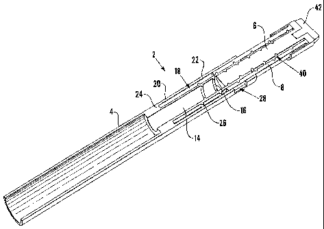
The present invention relates to a medicament delivery device such as an
injector for self-administration of a medicament. There is a need to display
the amount of the dialled dosage of medicament on the rotatable knob in
figures sufficiently large and clear to be legible by those users having a
degree of impaired vision. There is disclosed a dose dial mechanism for a
medicament delivery device having a housing (4), the dose dial mechanism
comprising a dose dial element (6) having a first thread (40) for engagement
with the housing (4) and a dial sleeve member (8) having a second thread (48)
for engagement with the housing (4) in which the dial sleeve member (8) is
coupled to the dose dial element (6) so as to allow relative axial movement
and inhibit relative rotational movement therebetween, and in which the pitch
of the second thread (48) is different from the pitch of the first thread (40)
so as to cause a different axial displacement of the dial sleeve member during
axial displacement of the dose dial element.


French Abstract

L'invention concerne un distributeur de médicament tel qu'un injecteur pour une auto-administration d'un médicament. La quantité du dosage sélectionné de médicament est affichée sur la spicule rotative en chiffres suffisamment large et clairs, de façon à être lisible par les utilisateurs présentant un degré de vision détérioré. L'invention concerne un mécanisme de sélection de dose pour un dispositif d'administration de médicaments présentant un logement (4). Ledit mécanisme de sélection de dose comprend un élément de sélection de dose (6) présentant un premier filetage (40) destiné à mettre en contact le logement (4) et un élément manchon de sélection (8) présentant un second filetage (48) destiné à mettre en contact le logement (4) dans lequel l'élément manchon de sélection (8) est couplé à l'élément de sélection de dose (6), ceci permettant un mouvement axial relatif et empêchant le mouvement rotatif relatif. Selon l'invention, l'inclinaison du second filetage (48) dans le mécanisme est différente de celle du premier filetage (40) de façon à provoquer un déplacement axial différent dudit élément manchon de sélection lors de son déplacement.

Claims

Note: Claims are shown in the official language in which they were submitted.


8
CLAIMS
1. A medicament delivery device having a housing and a dose dial
mechanism; the dose dial mechanism comprising:
a dose dial element having a first thread engaging with the housing;
and a dial sleeve member having a second thread engaging with the
housing;
wherein the dial sleeve member is coupled to the dose dial element so as
to allow relative axial movement and inhibit relative rotational movement
therebetween ; and wherein the pitch of the second thread is different from
the
pitch of the first thread so as to cause a different axial displacement of the
dial
sleeve member during axial displacement of the dose dial element.
2. The medicament delivery device according to claim 1, in which the pitch
of the second thread is greater than the pitch of the first thread.
3. The medicament delivery device according to claim 2 wherein the pitch of
the second thread is one and one half times greater than the pitch of the
first
thread.
4. The medicament delivery device according to claim 1, 2 or 3 wherein the
dose dial element comprises a central shaft element having a first end and a
second end, and including a radially outwardly directed flange at the first
end of
the shaft element, and a skirt depending from an end of the radially outwardly
directed flange remote from the shaft element, such that the skirt, the
radially
outwardly directed flange and the first end of the shaft element define a
groove at
the first end of the shaft member and a first helical groove at the second end
of the
shaft element.

Description

Note: Descriptions are shown in the official language in which they were submitted.


CA 02478356 2004-09-08
WO 03/075985 PCT/GB03/00782
IMPROVEMENTS IN AND RELATING TO A DOSING MECHANISM FOR A MEDICAMENT
DELIVERY DE-VICE
The present invention relates to a medicament delivery device, and in
particular, but
not exclusively, to a medicament delivery device such as an injector for
self administration of a medicament. Such injectors include those known as pen-
type
injectors.
In the past, it was known for those requiring regular injections of a
medicament, such
as those having diabetes requiring injections of insulin, to use a syringe to
remove a
required amount of medicament from a phial, and then use the syringe to inject
the
required amount of medicament. There are a number of drawbacks with this
method.
These include the fact that the loading of the syringe in this way is a
delicate and
somewhat skilled task, while those with, for example diabetes, are often
infirm or
have impaired vision, each of which increases the risk of inadvertent pricking
upon
the syringe. In addition, the use of syringes in public places has
increasingly become
socially unacceptable. To overcome these difficulties pen-type injectors have
been
developed.
Such injectors include within a main housing a medicament camidge. The
medicament cartridge is supplied loaded with a medicament. A user then selects
a
dosage and uses the pen-type injector to deliver the selected amount of
medicament.
The pen-type injectors axe, as the name suggests, typically in the shape of a
pen,
though sometimes other forms are adopted. In each case, however, the
appearance is
non-descript so as not to draw attention to the device.
Often, the medicament cartridge is replaceable to facilitate reuse of the
injector. As
noted above, those using such devices are often infirm or have impaired
vision. There
is accordingly a demand for a medicament delivery device in which an amount of
a
dosage of medicament to be delivered can be selected relatively quickly by the
firm
and infirm alike and in which the amount of the dosage may readily be
controlled and
determined.

CA 02478356 2004-09-08
WO 03/075985 PCT/GB03/00782
2
It is known to provide a pen-type injector with a dose dial mechanism
comprising a
rotatable knob disposed at one end of the injector. The rotatable knob is
connected
either directly or indirectly with a drive means. The drive means acts upon a
medicament cartridge located within the injector to cause medicament to be
expelled
from the inj ector. The rotatable knob conveniently comprises a helical dial.
However, it is a problem with known devices of this type to display the amount
of the
dialled dosage of medicament on the rotatable knob in figures sufficiently
large and
clear to be legible by those users having a degree of impaired vision.
According to a first aspect of the invention, there is provided a dose dial
mechanism
for a medicament delivery device having a housing, the dose dial mechanism
comprising:
a dose dial element having a first thread for engagement with the housing;
and a dial sleeve member having a second thread for engagement with the
housing;
wherein the dial sleeve member is coupled to the dose dial element so as to
allow
relative axial movement and inhibit relative rotational movement therebetween;
and wherein the pitch of the second thread is different from the pitch of the
first
thread so as to cause a different axial displacement of the dial sleeve member
during
axial displacement of the dose dial element.
Preferably, the pitch of the second thread is greater than the pitch of the
first thread.
More preferably, the pitch of the second thread is one and one half times
greater than
the pitch of the first thread.
Advantageously, the dose dial element comprises a central shaft element having
a first
end and a second end, and including a radially outwardly directed flange at
the first
end of the shaft element, and a skirt depending from an end of the radially
outwardly
directed flange remote from the shaft element, such that the skirt, the
radially
outwardly directed flange and the first end of the shaft element define a
groove at the
first end of the shaft member and a first helical groove at the second end of
the shaft
element.

CA 02478356 2004-09-08
WO 03/075985 PCT/GB03/00782
3
According to a second aspect of the invention a medicament delivery device
comprises a dose dial mechanism according to the first aspect of the
invention.
The invention will now be described, by way of example only, with reference to
the
accompanying drawings, in which:-
Figure 1 shows a section through a medicament delivery device in accordance
with
the present invention with the dose dial element and the dial sleeve member in
a first
position; and
Figure 2 shows a section similar to Figure 1 with the dose dial element and
the dial
sleeve member in a second position.
Referring to the Figures, there may be seen a section through a medicament
delivery
device 2 comprising a dose dial mechanism in accordance with the present
invention.
The medicament delivery device 2 comprises a generally elongate housing 4 of
generally cylindrical configuration. At a first end of the housing 4 there is
located the
dose dial mechanism including a dose dial element 6 and a dial sleeve member
8.
Within the second end of the housing there is provided a cavity 10 within
which a
medicament cartridge (not shown) may be retained. It will be understood by
those
skilled in the art that the medicament delivery device will comprise further
elements
not shown in the drawings including but not limited to a needle unit and a cap
for
covering the needle unit when the medicament delivery device is not in use to
prevent
inadvertent pricking upon the needle unit.
The housing is provided at the first end with a bore 12 having a fixed
diameter.
Preferably, this diameter is less than that of the cavity 10. More preferably,
this
diameter is less than the diameter of an inner diameter of a medicament
cartridge (not
shown) housed within the second end of the housing 4. An inner surface 14 of
the
bore 12 is provided with a first screw thread 16 having a first fixed pitch.
Concentric with the bore 12 in the first end of the housing 4 there is
provided an
axially disposed groove 18. The axially disposed groove 18 comprises an inner
surface 20, an outer surface 22 and a base surface 24 connecting the inner
surface 20

CA 02478356 2004-09-08
WO 03/075985 PCT/GB03/00782
4
and the outer surface 22. The inner surface 20 of the axially disposed groove
18 is
provided with a second screw thread 26 having a second fixed pitch. An opening
28
is provided through the outer surface 22 of the axially disposed groove 18
through~to
an outer surface 30 of the housing 4.
The dose dial element 6 and the dial sleeve member 8 are adapted to work
within the
first end of the housing 4. The dose dial element 6 and the dial sleeve member
8 are
connected together in such a way as to inhibit or substantially prevent
relative rotation
therebetween such that rotation of the dose dial element 6 relative to the
housing 4,
for example by a user, causes a corresponding rotation of the dial sleeve
member 8
relative to the housing 4. This may preferably be achieved by way of a spline
arrangement (not shown) though any other suitable arrangement may be adopted.
In the illustrated embodiment, the dose dial element 6 may be seen to comprise
a
central shaft element 32 having a first end and a second end. The first end of
the shaft
element 32 is provided with a radially outwardly directed flange 34. A skirt
36
depends from an end of the radially outwardly directed flange 34 remote from
the
shaft element 32. The skirt 36, the radially outwardly directed flange 34 and
the first
end of the shaft element 32 in this way define an axially extending groove 38
at the
first end of the shaft element 32. A first helical groove 40 is provided at
the second
end of the shaft element 32. The pitch of the first helical groove 40 is the
same as that
of the first screw thread 16. In use, the first screw thread 16 runs within
the first
helical groove 40.
In use, the second end of the shaft element 32 is adapted to drive a piston
(not shown)
located within a retained medicament cartridge (not shown) to expel a
medicament
from within the medicament cartridge.
In the illustrated embodiment a button 42, generally T-shaped in section, is
provided
in engagement with a suitably shaped recess in the first end of the dose dial
element 6
such that the button 42 is able to freely rotate relative to the dose dial
element 6. The
button 42 may be of a softer material than the rest of the medicament delivery
device

CA 02478356 2004-09-08
WO 03/075985 PCT/GB03/00782
S
to provide a more pleasing tactile experience for a user when operating the
medicament delivery device 2.
The dial sleeve member 8 comprises a generally cylindrical member having an
inner
wall 44 and an outer wall 46. The inner wall 44 is provided with a second
helical
groove 48. The pitch of the second helical groove 48 is the same as that of
the second
screw thread 26. In use, the second screw thread 26 runs within the second
helical
groove 48. The dial sleeve member 8 is provided with a plurality of numbers
(not
shown) upon the outer wall 46 corresponding to a desired dosage to be dialled.
The
numbers are arranged in a generally helical pattern around the dial sleeve
member 8,
corresponding substantially to the second screw thread, such that each number
becomes visible in turn through the opening 28 in the housing 4 as the dose
dial
element 6 is rotated by a user, as described below.
In use, the dose dial mechanism is adapted to be moved between two extreme
positions. In the first extreme position shown in Figure 1, no dosage of
medicament
has been dialled and the skirt 36 of the dose dial element 6 is disposed
adjacent, or
substantially in abutment with, the first end of the housing 4. The dial
sleeve member
8 is retained substantially within the axially disposed groove 18 of the
housing 4, and
extends only a small amount within the axially extending groove 38 of the dose
dial
element 6.
To dial a dosage of medicament to be delivered, the user twists or rotates the
dose dial
element 6 relative to the housing 4. The rotation of the dose dial element 6
relative to
the housing 4 causes an axial movement of the dose dial element 6 relative to
the
housing 4 by virtue of the first screw thread 16. Thus, as the dose dial
element 6 is
rotated, it extends from the housing towards the second extreme position.
Furthermore, owing to the connection between the dose dial element 6 and the
dial
sleeve member 8 described above, the rotation of the dose dial element 6
causes a
corresponding rotation of the dial sleeve member 8 relative to the housing 4.
The
rotation of the dial sleeve member 8 relative to the housing 4 also causes an
axial
movement of the dial sleeve member 8 relative to the housing 4 by virtue of
the

CA 02478356 2004-09-08
WO 03/075985 PCT/GB03/00782
6
second screw thread. Thus, as the dial sleeve member 8 is rotated (through
rotation of
the dose dial element 6 by the user) it also extends from the housing 4
towards the
second extreme position.
In the second extreme position shown in Figure 2, a maximum dosage of
medicament
has been dialled. The skirt of the dose dial element 6 is disposed a distance
from the
first end of the housing 4 while the dial sleeve member 8 extends from within
the
axially disposed groove 18 of the housing 4. In this position, the dial sleeve
member
8 substantially fills the axially disposed groove 18 of the housing 4.
It will be appreciated that, owing to the difference in pitch between the
first and
second screw threads, the axial movement of the dose dial element 6 relative
to the
housing 4 will be different from that of the dial sleeve member 8. In a
preferred
embodiment the pitch of the second screw thread 26 is 1.5 times greater than
the pitch
of the first screw thread 16. Thus, when the dose dial element 6 is rotated by
the user,
the dial sleeve member 8 moves 1.5 times further along its axis than the dose
dial
element 6.
Since the dial sleeve member 8 moves a greater distance than the dose dial
element 6,
each of the dosage numbers may be spaced further apart from one another or
made
larger than if the dosage numbers were to be located directly upon a drive
member or
upon the dose dial element itself.
To deliver the dosage of medicament, the user presses the button 42 to exert
an axial
force on the dose dial element 6 thereby to cause the dose dial mechanism to
move
axially towards the first extreme position. As the dose dial mechanism moves
towards
the first extreme position, the dose dial element 6 engages with the piston
located
within the retained medicament cartridge thereby to expel the medicament from
the
cartridge.
In addition, as the dose dial mechanism moves towards the first extreme
position, the
first thread 16 causes the dose dial element 6 to rotate relative to the
housing 4 while
the second thread and the non-rotatable connection between the dose dial
element 6

CA 02478356 2004-09-08
WO 03/075985 PCT/GB03/00782
7
and the dial sleeve member 8 cause the dial sleeve member to rotate relative
to the
housing 4.
The rotatable engagement of the button 42 with the dose dial element 6 allows
the
former to remain rotationally fixed relative to the user as the latter rotates
thereby to
permit easier movement of the dose dial mechanism.
Once again, the increased pitch of the second screw thread compared with the
first
screw thread causes the dial sleeve member 8 to move further axially than the
dose
dial element 6, thereby to return the dose dial mechanism to the first extreme
position
as shown in Figure 1.

Representative Drawing
A single figure which represents the drawing illustrating the invention.
Administrative Status

2024-08-01:As part of the Next Generation Patents (NGP) transition, the Canadian Patents Database (CPD) now contains a more detailed Event History, which replicates the Event Log of our new back-office solution.

Please note that "Inactive:" events refers to events no longer in use in our new back-office solution.

For a clearer understanding of the status of the application/patent presented on this page, the site Disclaimer , as well as the definitions for Patent , Event History , Maintenance Fee  and Payment History  should be consulted.

Event History

Description Date
Time Limit for Reversal Expired 2018-03-06
Letter Sent 2017-03-06
Grant by Issuance 2011-04-19
Inactive: Cover page published 2011-04-18
Inactive: Final fee received 2011-01-11
Pre-grant 2011-01-11
Notice of Allowance is Issued 2010-07-19
Letter Sent 2010-07-19
Notice of Allowance is Issued 2010-07-19
Inactive: Approved for allowance (AFA) 2010-07-16
Amendment Received - Voluntary Amendment 2010-07-05
Inactive: S.30(2) Rules - Examiner requisition 2010-01-04
Letter Sent 2008-04-29
Request for Examination Requirements Determined Compliant 2008-03-06
All Requirements for Examination Determined Compliant 2008-03-06
Request for Examination Received 2008-03-06
Letter Sent 2005-07-07
Inactive: Single transfer 2005-06-07
Inactive: Cover page published 2004-11-09
Inactive: Courtesy letter - Evidence 2004-11-09
Inactive: Notice - National entry - No RFE 2004-11-05
Application Received - PCT 2004-10-01
National Entry Requirements Determined Compliant 2004-09-08
Application Published (Open to Public Inspection) 2003-09-18

Abandonment History

There is no abandonment history.

Maintenance Fee

The last payment was received on 2011-02-14

Note : If the full payment has not been received on or before the date indicated, a further fee may be required which may be one of the following

  • the reinstatement fee;
  • the late payment fee; or
  • additional fee to reverse deemed expiry.

Patent fees are adjusted on the 1st of January every year. The amounts above are the current amounts if received by December 31 of the current year.
Please refer to the CIPO Patent Fees web page to see all current fee amounts.

Owners on Record

Note: Records showing the ownership history in alphabetical order.

Current Owners on Record
DCA DESIGN INTERNATIONAL LIMITED
Past Owners on Record
MICHAEL CAMERON BAINTON
Past Owners that do not appear in the "Owners on Record" listing will appear in other documentation within the application.
Documents

To view selected files, please enter reCAPTCHA code :


To view images, click a link in the Document Description column (Temporarily unavailable). To download the documents, select one or more checkboxes in the first column and then click the "Download Selected in PDF format (Zip Archive)" or the "Download Selected as Single PDF" button.

List of published and non-published patent-specific documents on the CPD .

If you have any difficulty accessing content, you can call the Client Service Centre at 1-866-997-1936 or send them an e-mail at CIPO Client Service Centre.

({010=All Documents, 020=As Filed, 030=As Open to Public Inspection, 040=At Issuance, 050=Examination, 060=Incoming Correspondence, 070=Miscellaneous, 080=Outgoing Correspondence, 090=Payment})


Document
Description 
Date
(yyyy-mm-dd) 
Number of pages   Size of Image (KB) 
Drawings 2004-09-07 2 39
Description 2004-09-07 7 307
Representative drawing 2004-09-07 1 25
Claims 2004-09-07 1 37
Abstract 2004-09-07 1 68
Claims 2010-07-04 1 34
Representative drawing 2011-03-20 1 15
Notice of National Entry 2004-11-04 1 193
Courtesy - Certificate of registration (related document(s)) 2005-07-06 1 114
Reminder - Request for Examination 2007-11-06 1 119
Acknowledgement of Request for Examination 2008-04-28 1 190
Commissioner's Notice - Application Found Allowable 2010-07-18 1 164
Maintenance Fee Notice 2017-04-17 1 178
PCT 2004-09-07 10 326
Correspondence 2004-11-04 1 27
Fees 2006-03-05 1 38
Correspondence 2011-01-10 1 40