Language selection

Search

Patent 2478382 Summary

Third-party information liability

Some of the information on this Web page has been provided by external sources. The Government of Canada is not responsible for the accuracy, reliability or currency of the information supplied by external sources. Users wishing to rely upon this information should consult directly with the source of the information. Content provided by external sources is not subject to official languages, privacy and accessibility requirements.

Claims and Abstract availability

Any discrepancies in the text and image of the Claims and Abstract are due to differing posting times. Text of the Claims and Abstract are posted:

  • At the time the application is open to public inspection;
  • At the time of issue of the patent (grant).
(12) Patent: (11) CA 2478382
(54) English Title: A PAINT ROLLER FOR SELECTIVELY APPLYING PAINT AT SURFACE CORNERS
(54) French Title: ROULEAU A PEINTURE POUR APPLICATION SELECTIVE DE PEINTURE DANS LES COINS
Status: Term Expired - Post Grant Beyond Limit
Bibliographic Data
(51) International Patent Classification (IPC):
  • B05C 17/02 (2006.01)
  • B05C 17/025 (2006.01)
  • B05C 17/035 (2006.01)
(72) Inventors :
  • ER, POH LEONG (Singapore)
(73) Owners :
  • POH LEONG ER
(71) Applicants :
  • POH LEONG ER (Singapore)
(74) Agent: OYEN WIGGS GREEN & MUTALA LLP
(74) Associate agent:
(45) Issued: 2011-05-10
(86) PCT Filing Date: 2003-01-24
(87) Open to Public Inspection: 2003-10-09
Examination requested: 2008-01-23
Availability of licence: N/A
Dedicated to the Public: N/A
(25) Language of filing: English

Patent Cooperation Treaty (PCT): Yes
(86) PCT Filing Number: PCT/SG2003/000015
(87) International Publication Number: SG2003000015
(85) National Entry: 2004-09-01

(30) Application Priority Data:
Application No. Country/Territory Date
200201815-8 (Singapore) 2002-04-01

Abstracts

English Abstract


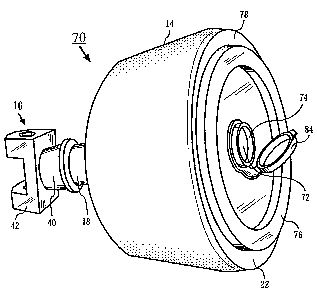
A paint roller (10) has a frustoconically-shaped applicator (12), a paint-
absorbable member (14) and a movement coupler (16). The applicator (12) has a
coupling portion (18) and two opposite ends (20, 22) and is rotatable at the
coupling portion (18) about a rotary axis (24). The end (20) is a coupling end
(20) that has a planar cross-section smaller than that of the other end (22).
The coupling portion (18) is formed at the coupling end (20) and is disposed
centrally thereat. The movement coupler (16) has a rotary connecting portion
(40) that is detachably coupled to the applicator (12) at the coupling portion
(18) for rotary movement about the rotary axis (24) and a pivotal connecting
portion (42) that is adapted to coact with a pivot mount of a handle (not
shown) for pivotal movement of the applicator (12).


French Abstract

Ce rouleau à peinture (10) est constitué d'un applicateur tronconique (12), d'un élément absorbant la peinture (14) et d'un coupleur de mouvement (16). L'applicateur (12), qui comporte une pièce d'accouplement (18) et deux extrémités opposées (20, 22), tourne, à la hauteur de la pièce d'accouplement (18) autour d'un axe (24). L'extrémité (20) est une extrémité d'accouplement dont la section transversale est plus petite que celle de l'autre extrémité (22). La pièce d'accouplement (18), qui est formée à l'extrémité d'accouplement (20), est centrée. Le coupleur de mouvement (16)qui a une partie de connexion rotative (40), montée détachable sur l'applicateur (12), au niveau de la pièce d'accouplement (18), pour une rotation autour de l'axe (24), a également une partie de connexion pivotante (42) conçue pour agir en coopération avec un montage en pivot de la poignée (non représenté) pour faire pivoter l'applicateur (12).

Claims

Note: Claims are shown in the official language in which they were submitted.


8
WHAT IS CLAIMED IS:
1. A paint roller comprising:
a frustoconically-shaped applicator having two opposite ends, a
coupling portion disposed at a first end of said opposite ends, and an
external surface between said two opposite ends, said
frustoconically-shaped applicator being rotatable at said coupling
portion about a rotary axis; said frustoconically-shaped applicator
comprising a chamber for storing paint; and at least one
paint-absorbable member mounted to said external surface,
wherein said frustoconically-shaped applicator comprises at least
one closable inlet leading into said chamber, said closable inlet being
disposed at a second end of said opposite ends such that the rotary axis
of said applicator passes through the closable inlet,
and wherein said chamber comprises at least one paint-permeable
portion coupled to said at least one paint-absorbable member.
2. The paint roller as claimed in Claim 1, and further comprising a
movement coupler detachably coupled to said coupling portion.
3. The paint roller as claimed in Claim 2, wherein said movement coupler
comprises a rotary connecting portion adapted to coact with said
coupling portion for rotary movement about said rotary axis.
4. The paint roller as claimed in Claim 2, wherein said movement coupler
comprises a pivotal connecting portion adapted to coact with a pivot
mount of a handle for pivotal movement of said frustoconically-shaped
applicator.

9
5. The paint roller as claimed in Claim 1, wherein the first one of said
opposite ends is a coupling end, said coupling portion being formed at
said coupling end.
6. The paint roller as claimed in Claim 5, wherein said coupling end has a
planar cross-section smaller than a corresponding planar cross-section
of the second one of said opposite ends.
7. The paint roller as claimed in Claim 6, wherein said coupling portion is
disposed centrally relative to said planar cross-section of said coupling
end.
8. The paint roller as claimed in Claim 1, and further comprising at least
one abutment member mountable to the second one of said opposite
ends.

Description

Note: Descriptions are shown in the official language in which they were submitted.


CA 02478382 2004-09-O1
WO 03/082479 PCT/SG03/00015
A PAINT ROLLER FOR SELECTIVELY APPLYING PAINT AT
SURFACE CORNERS
Field of the Invention
The present invention relates to apparatus for applying fluids such as, for
example, paint onto surfaces. In particular, the present invention relates to
a paint
roller for selectively applying paint at surface corners.
Background of the Invention
Paint rollers for applying paint onto surfaces are known. Typically, such
paint
rollers have paint-absorbing surfaces that are dipped into paint containers
and then
rolled over surfaces that are to be painted. Another type of paint rollers has
a
permeable surface through which paint, stored inside such paint rollers, can
flowy
i
through for application onto surfaces that are to be painted.
Generally, existing paint rollers works well for a flat surface on which only
a
single paint shade or color is to be applied. However, a problem arises when
such
paint rollers are used to apply paint at surface corners formed, for example,
by two
walls or between a wall and a ceiling. This is a problem because paint desired
on one
surface may be undesirably applied onto an adjacent surface.
Prior art paint rollers that alleviate the above problem include US Patent
5,623,740, issued to Burns et al., in which an apparatus provides a guard
shield that
acts as a barrier to paint being applied onto an adjacent surface. Such prior
art paint
rollers provide shield-like barriers or guards that are detachably mounted to
the paint
rollers. However, use of the shield-like barriers or guards causes other
problems. For
example, a guard may be required to contact an adjacent surface for alignment
purposes as well and this is a problem when an adjacent surface has wet paint
or is
delicate. Consequently, the adjacent surface can be damaged by abrasion with
the

CA 02478382 2004-09-O1
WO 03/082479 PCT/SG03/00015
2
guard. Furthermore, shield-like barriers or guards are accessories that
typically
require assembling or attaching, which adds complexity to prior art paint
rollers.
Therefore, a need clearly exists for a novel paint roller for selectively
applying paint at surface corners and that does not need separate accessories
such as
a barrier or a guard to be assembled or attached.
Brief Summary of the Invention
The present invention seeks to provide a paint roller for selectively applying
paint at surface corners.
Accordingly, in one aspect, the present invention provides a paint roller
comprising:
a frustoconically-shaped applicator having two opposite ends, a
coupling portion disposed at one of the opposite ends, and an external
surface between the two opposite ends, the frustoconically-shaped
applicator being rotatable at the coupling portion about a rotary axis;
and
at least one paint-absorbable member mounted to the external
surface.
In another aspect, the present invention provides a paint roller comprising:
a frustoconically-shaped applicator having two opposite ends, a
coupling portion disposed at one of the opposite ends, and an external
surface between the two opposite ends, the frustoconically-shaped
applicator being rotatable at the coupling portion about a rotary axis;
at least one paint-absorbable member mounted to the external
surface;
a handle having a pivot mount;
and

CA 02478382 2004-09-O1
WO 03/082479 PCT/SG03/00015
3
a movement coupler detachably coupled to the coupling portion
and to the pivot mount.
Brief Description of the Drawings
A preferred embodiment and alternate embodiments of the present invention
are described, by way of example, with reference to the drawings of which:
FIG. 1 is a perspective view of a paint roller comprising a frustoconically-
shaped applicator and a movement coupler in accordance with the preferred
embodiment;
FIG. 2 is a side view of the paint roller of FIG. l;
FIG. 3 is an end view of the paint roller of FIG. 1 looking at one opposite
end
of the frustoconically-shaped applicator;
FIG. 4 is an end view of the paint roller of FIG. 1 looking at the other
opposite end of the frustoconically-shaped applicator;
FIG. 5 is a perspective view of the paint roller of FIG. 1 with the movement
coupler separated and a part of a handle for the paint roller;
FIG. 6 is a perspective view of a paint roller in accordance with an alternate
embodiment of the present invention;
and
FIG. 7 is a side view of a frustoconically-shaped applicator for the paint
roller
of FIG. 6.

CA 02478382 2004-09-O1
WO 03/082479 PCT/SG03/00015
4
Detailed Description of the Drawings
A paint roller in accordance with a preferred embodiment and an alternate
embodiment of the invention are described. In the following description,
details are
provided to describe these embodiments. However, it shall be apparent to one
skilled
in the art that the invention may be practiced without such details. Some of
these
details may not be described at length so as not to obscure the invention.
There are many advantages of the embodiments of the invention. One
advantage of the embodiments is that contact with an adjacent surface by a
paint-
absorbable member of the paint roller is avoided, or at least alleviated, when
using
the paint roller to paint a surface.
Another advantage of the embodiments of the invention is that the paint roller
is simple to use and does not require an accessory such as a barrier or a
guard.
Without such an accessory, the likelihood of contact with an adjacent surface
having
wet paint or damage to the adjacent surface is avoided or reduced.
A further advantage of the invention is that the paint roller can receive
paint
directly onto a paint-absorbable member from an external paint container in
the
preferred embodiment. In an alternate embodiment, the paint roller has a
chamber
that stores paint and that is coupled to the paint-absorbable member via at
least one
paint-permeable portion.
Referring now to FIG. 1, a perspective view of a paint roller 10 in accordance
with the preferred embodiment of the invention is illustrated. The paint
roller 10
comprises a frustoconically-shaped applicator 12, a paint-absorbable member 14
and
a movement coupler 16.
The frustoconically-shaped applicator 12 has a coupling portion 18 and two
opposite ends 20,22 and is rotatable at the coupling portion 18 about a rotary
axis 24.
The opposite end 20 is a coupling end 20 that has a planar cross-section
smaller than

CA 02478382 2004-09-O1
WO 03/082479 PCT/SG03/00015
a corresponding planar cross-section of the other opposite end 22. The
coupling
portion 18 is formed at the coupling end 20 and is disposed centrally relative
to the
planar cross-section of the coupling end 20.
5 The paint-absorbable member 14 is mounted to an external surface 30 of the
frustoconically-shaped applicator 12 between the two opposite ends 20,22. The
external surface 30 is indicated in a side view of the paint roller 10 shown
in FIG. 2.
The paint-absorbable member 14 can be formed with foam or sponge-like
material.
The movement coupler 16 is detachably coupled to the frustoconically-
shaped applicator 12 at the coupling portion 18. The movement coupler 16
comprises
a rotary connecting portion 40 and a pivotal connecting portion 42. The rotary
connecting portion 40 is adapted to coact with the coupling portion 18 for
rotary
movement of the frustoconically-shaped applicator 12 about the rotary axis 24.
The
pivotal connecting portion 42 is adapted to coact with a pivot mount of a
handle (not
shown) for pivotal movement of the frustoconically-shaped applicator 12.
FIG. 3 is an end view of the paint roller 10 looking at the opposite end 22
and
FIG. 4 is an end view of the paint roller 10 looking at the other opposite or
coupling
end 20. In these end views, disposition of the paint-absorbable member 14, the
external surface 30 and the movement coupler 16 relative to each other are
illustrated. In addition, these end views illustrate the planar cross-section
of the two
opposite ends 20,22.
Referring now to FIG. S, a perspective view of the paint roller 10 with the
movement coupler 16 separated and a part of handle 50 for the paint roller 10
is
illustrated. The handle 50 has a pivot mount 52 that couples to the pivotal
connecting
portion 42 of the movement coupler 16. Apertures 54,56 are provided,
respectively,
at the pivotal connecting portion 42 and the pivot mount 52 to enable a pivot
coupling thereat. With the apertures 54a,54b and a pin (not shown), the
pivotal
connecting portion 42 is adapted to coact with the pivot mount 52 for pivotal

CA 02478382 2004-09-O1
WO 03/082479 PCT/SG03/00015
6
movement of the frustoconically-shaped applicator 12. The coupling portion 18
has a
knob 58 that couples to an aperture 60 of the rotary connecting portion 40 of
the
movement coupler 16.
A perspective view of a paint roller 70 in accordance with an alternate
embodiment of the present invention is illustrated in FIG. 6. Other than
elements
similar to the paint roller 10, the paint roller 70 further comprises a
chamber 72 for
storing paint, a closable inlet 74 that leads into the chamber 72 and an
abutment
member 76. The abutment member 76 is mounted to the opposite end 22 and serves
to alleviate contact of the paint-absorbable member 14 with adjacent surfaces
that are
not being painted.
Referring to FIG. 7, a side view of a frustoconically-shaped applicator 78 for
the paint roller 70 is illustrated. The frustoconically-shaped applicator 78
comprises
at least one paint-permeable portion 80. In this alternate embodiment, the at
least one
paint-permeable portion 80 comprises slits 82 through which paint is provided
to the
paint-absorbable member 14 from the chamber 72. The closable inlet 74 is
disposed
at the opposite end 22 and has a cover 84. Paint is poured into the chamber 72
via the
closable inlet 74 and the chamber 72 is then capped using the cover 84.
While the present invention has been described in detail for the above
embodiments with reference to FIGS. 1 to 7, it should be understood that FIGs.
1 to 7
are illustrative of the embodiments without limiting the invention. For
example, the
paint-permeable portion 80 has the slits 82 oriented as shown in FIG. 7.
However,
other shapes and different orientation of such shapes may be provided at the
paint-
permeable portion 80. Also, the closable inlet 74 may be placed at other
locations
that do not restrict or limit movement of the frustoconically-shaped
applicator 78.
Furthermore, coupling between the coupling portion 18 and the movement coupler
16 may also be provided in another manner although not shown in the
embodiments
as described and illustrated. Accordingly, persons skilled in the art can make
various

CA 02478382 2004-09-O1
WO 03/082479 PCT/SG03/00015
modifications and improvements without departing from the spirit and the scope
of
the present invention.

Representative Drawing
A single figure which represents the drawing illustrating the invention.
Administrative Status

2024-08-01:As part of the Next Generation Patents (NGP) transition, the Canadian Patents Database (CPD) now contains a more detailed Event History, which replicates the Event Log of our new back-office solution.

Please note that "Inactive:" events refers to events no longer in use in our new back-office solution.

For a clearer understanding of the status of the application/patent presented on this page, the site Disclaimer , as well as the definitions for Patent , Event History , Maintenance Fee  and Payment History  should be consulted.

Event History

Description Date
Inactive: Expired (new Act pat) 2023-01-24
Common Representative Appointed 2019-10-30
Maintenance Request Received 2013-11-06
Inactive: Late MF processed 2013-11-06
Letter Sent 2013-01-24
Grant by Issuance 2011-05-10
Inactive: Cover page published 2011-05-09
Notice of Allowance is Issued 2011-03-08
Inactive: Office letter 2011-03-08
Inactive: Approved for allowance (AFA) 2011-02-24
Letter Sent 2011-02-09
Reinstatement Request Received 2011-01-24
Pre-grant 2011-01-24
Withdraw from Allowance 2011-01-24
Final Fee Paid and Application Reinstated 2011-01-24
Inactive: Final fee received 2011-01-24
Deemed Abandoned - Conditions for Grant Determined Not Compliant 2011-01-10
Letter Sent 2010-07-08
Notice of Allowance is Issued 2010-07-08
Inactive: Approved for allowance (AFA) 2010-07-06
Amendment Received - Voluntary Amendment 2010-04-06
Inactive: S.30(2) Rules - Examiner requisition 2009-10-07
Letter Sent 2008-04-11
Small Entity Declaration Request Received 2008-03-07
Small Entity Declaration Determined Compliant 2008-03-07
Request for Examination Received 2008-01-23
Request for Examination Requirements Determined Compliant 2008-01-23
All Requirements for Examination Determined Compliant 2008-01-23
Inactive: Cover page published 2004-11-08
Inactive: Inventor deleted 2004-11-01
Inactive: Notice - National entry - No RFE 2004-11-01
Correct Inventor Requirements Determined Compliant 2004-11-01
Application Received - PCT 2004-10-01
National Entry Requirements Determined Compliant 2004-09-01
Small Entity Declaration Determined Compliant 2004-09-01
Application Published (Open to Public Inspection) 2003-10-09

Abandonment History

Abandonment Date Reason Reinstatement Date
2011-01-24
2011-01-10

Maintenance Fee

The last payment was received on 2011-01-21

Note : If the full payment has not been received on or before the date indicated, a further fee may be required which may be one of the following

  • the reinstatement fee;
  • the late payment fee; or
  • additional fee to reverse deemed expiry.

Patent fees are adjusted on the 1st of January every year. The amounts above are the current amounts if received by December 31 of the current year.
Please refer to the CIPO Patent Fees web page to see all current fee amounts.

Fee History

Fee Type Anniversary Year Due Date Paid Date
Basic national fee - small 2004-09-01
MF (application, 2nd anniv.) - small 02 2005-01-24 2004-12-29
MF (application, 3rd anniv.) - small 03 2006-01-24 2005-09-14
MF (application, 4th anniv.) - small 04 2007-01-24 2007-01-22
Request for examination - small 2008-01-23
MF (application, 5th anniv.) - small 05 2008-01-24 2008-01-24
MF (application, 6th anniv.) - small 06 2009-01-26 2009-01-14
MF (application, 7th anniv.) - small 07 2010-01-25 2010-01-20
MF (application, 8th anniv.) - small 08 2011-01-24 2011-01-21
Final fee - small 2011-01-24
Reinstatement 2011-01-24
MF (patent, 9th anniv.) - standard 2012-01-24 2012-01-19
Reversal of deemed expiry 2013-01-24 2013-11-06
MF (patent, 10th anniv.) - small 2013-01-24 2013-11-06
MF (patent, 11th anniv.) - standard 2014-01-24 2014-01-15
MF (patent, 12th anniv.) - small 2015-01-26 2015-01-16
MF (patent, 13th anniv.) - standard 2016-01-25 2016-01-11
MF (patent, 14th anniv.) - small 2017-01-24 2017-01-12
MF (patent, 15th anniv.) - small 2018-01-24 2018-01-16
MF (patent, 16th anniv.) - small 2019-01-24 2018-11-20
MF (patent, 17th anniv.) - small 2020-01-24 2020-01-15
MF (patent, 18th anniv.) - small 2021-01-25 2021-01-18
MF (patent, 19th anniv.) - small 2022-01-24 2022-01-17
Owners on Record

Note: Records showing the ownership history in alphabetical order.

Current Owners on Record
POH LEONG ER
Past Owners on Record
None
Past Owners that do not appear in the "Owners on Record" listing will appear in other documentation within the application.
Documents

To view selected files, please enter reCAPTCHA code :


To view images, click a link in the Document Description column (Temporarily unavailable). To download the documents, select one or more checkboxes in the first column and then click the "Download Selected in PDF format (Zip Archive)" or the "Download Selected as Single PDF" button.

List of published and non-published patent-specific documents on the CPD .

If you have any difficulty accessing content, you can call the Client Service Centre at 1-866-997-1936 or send them an e-mail at CIPO Client Service Centre.

({010=All Documents, 020=As Filed, 030=As Open to Public Inspection, 040=At Issuance, 050=Examination, 060=Incoming Correspondence, 070=Miscellaneous, 080=Outgoing Correspondence, 090=Payment})


Document
Description 
Date
(yyyy-mm-dd) 
Number of pages   Size of Image (KB) 
Claims 2004-08-31 4 127
Drawings 2004-08-31 4 62
Representative drawing 2004-08-31 1 10
Description 2004-08-31 7 243
Abstract 2004-08-31 1 58
Claims 2010-04-05 2 58
Representative drawing 2011-03-15 1 10
Reminder of maintenance fee due 2004-10-31 1 110
Notice of National Entry 2004-10-31 1 193
Reminder - Request for Examination 2007-09-24 1 127
Acknowledgement of Request for Examination 2008-04-10 1 177
Commissioner's Notice - Application Found Allowable 2010-07-07 1 164
Notice of Reinstatement 2011-02-08 1 170
Courtesy - Abandonment Letter (NOA) 2011-02-08 1 165
Maintenance Fee Notice 2013-03-06 1 171
Late Payment Acknowledgement 2013-11-18 1 163
PCT 2004-08-31 11 373
Correspondence 2008-03-06 2 79
Correspondence 2011-01-23 1 41
Correspondence 2011-03-07 1 20
Fees 2013-11-05 1 33
Fees 2017-01-11 1 25