Language selection

Search

Patent 2478454 Summary

Third-party information liability

Some of the information on this Web page has been provided by external sources. The Government of Canada is not responsible for the accuracy, reliability or currency of the information supplied by external sources. Users wishing to rely upon this information should consult directly with the source of the information. Content provided by external sources is not subject to official languages, privacy and accessibility requirements.

Claims and Abstract availability

Any discrepancies in the text and image of the Claims and Abstract are due to differing posting times. Text of the Claims and Abstract are posted:

  • At the time the application is open to public inspection;
  • At the time of issue of the patent (grant).
(12) Patent: (11) CA 2478454
(54) English Title: SLEWING RING
(54) French Title: COURONNE DE ROTATION
Status: Deemed Expired
Bibliographic Data
(51) International Patent Classification (IPC):
  • F16C 33/58 (2006.01)
  • F16C 33/38 (2006.01)
  • F16C 33/44 (2006.01)
  • F16C 33/78 (2006.01)
(72) Inventors :
  • CHATRY, DIDIER (France)
  • TERVE, DANIEL (France)
(73) Owners :
  • DEFONTAINE
(71) Applicants :
  • DEFONTAINE (France)
(74) Agent: SMART & BIGGAR LP
(74) Associate agent:
(45) Issued: 2008-11-18
(22) Filed Date: 2004-08-23
(41) Open to Public Inspection: 2005-02-27
Examination requested: 2004-08-23
Availability of licence: N/A
Dedicated to the Public: N/A
(25) Language of filing: English

Patent Cooperation Treaty (PCT): No

(30) Application Priority Data:
Application No. Country/Territory Date
03 10220 (France) 2003-08-27

Abstracts

English Abstract

The slewing ring (1) comprises a retainer (6) in metal of a certain hardness substantially equal to the hardness of rings (3,4), which is arranged between two the rings (3,4), the retainer is integral in rotation with rolling elements (2), and holds these elements regularly spaced apart in raceway (5). At least one contact ring (7a,7b,7c,7d) made of a material of different hardness to the hardness of the rings (3,4) and of the retainer (6), is arranged between two members formed by retainer (6) and by one of the two rings (3,4), the contact ring prevents any direct contact between these two members (3,6;4,6) and is fixed to one of these two members (3,6;4,6) and is able to come into contact with the other (6,3;6,4).


French Abstract

Une couronne de rotation (1) comprend un dispositif de retenue (6) en métal d'une certaine dureté essentiellement égale à la dureté des couronnes (3,4), qui est placé entre deux des couronnes (3,4), le dispositif de retenue est intégré en rotation avec les éléments roulants (2), et retient ces éléments régulièrement espacés dans une cage (5). Au moins une couronne de contact (7a,7b,7c,7d) fabriquée d'un matériau de dureté différente de la dureté des couronnes (3,4) et du dispositif de retenue (6), est placée entre les deux éléments formés par le dispositif de retenue (6) et par une des deux couronnes (3,4), la couronne de contact empêche tout contact direct entre ces deux éléments (3,6;4,6) et est fixée à un de ces deux éléments (3,6;4,6) et peut venir en contact avec l'autre (6,3;6,4).

Claims

Note: Claims are shown in the official language in which they were submitted.

5
CLAIMS
1. Slewing ring comprising:
(a) rolling elements;
(b) inner and outer concentric metal rings of certain
hardness mobile in rotation relative to one another and
forming a raceway for the rolling elements;
(c) a retainer in metal of certain hardness
substantially equal to the hardness of the metal rings,
arranged between the metal rings, integral in rotation
with the rolling elements, and holding these elements
regularly spaced apart in the raceway; and
(d) at least one circular contact element made in a
material of different hardness to the metal rings and
retainer, the contact element being housed in a groove
made in one of the metal rings, and wherein the
retainer comes in contact against the contact element
for preventing any direct contact between the retainer
and the metal ring in which the groove is made.
2. Slewing ring as defined in claim 1, wherein the metal
rings and retainer are in steel and the contact element
is in a non-ferrous material.
3. Slewing ring as defined in claim 1 or 2, wherein each
of the inner and outer rings comprises at least one
groove for receiving each contact element.
4. Slewing ring as defined in any one of claims 1 to 3,
wherein at least one groove is formed on either side of
the raceway for receiving each contact element.

6
5. Slewing ring as defined in any one of claims 1 to 4,
wherein each contact element has a trapezoidal,
rectangular or semi-circular straight section.
6. Slewing ring as defined in any one of claims 1 to 5,
wherein each contact element is made in a compact, non-
porous material.
7. Slewing ring as defined in any one of claims 1 to 6,
wherein each contact element is made of copper or
bronze alloy.
8. Slewing ring as defined in any one of claims 1 to 6,
wherein each contact element is made in polyamide or
polytetrafluoroethylene.
9. Slewing ring as defined in any one of claims 1 to 8,
wherein each contact element is fixed to its
corresponding metal ring mechanically, metallurgically
or chemically.
10. Slewing ring as defined in any one of claims 1 to 9
wherein the rolling elements are ball elements.

Description

Note: Descriptions are shown in the official language in which they were submitted.


CA 02478454 2007-11-16
1
SLEWING RING
Field of the invention
The present invention pertains to a slewing ring, in
particular a ball bearing.
Background of the invention
A slewing ring is known of the type comprising rolling
elements, two concentric rings in metal of certain hardness
one inner and one outer, mobile in rotation relative to one
another and forming a raceway for the rolling elements, and
a metal retainer whose hardness is substantially similar to
that of the rings, arranged between the latter, integral in
rotation with the rolling elements and holding these
elements regularly spaced apart within the raceway.
A major disadvantage of this type of ring is that during the
rotation movement, the retainer comes into contact with the
rings and undergoes wear due to resulting friction. This
wear leads firstly to pollution of the lubricant whose
properties are thereby weakened, and secondly to reduced
lifetime of the rings.
On this account solutions have been put forward: heat and/or
chemical treatment of the surface of the rings at the point
of contact with the retainer (for example US 2001/48781 or
EP 0 531 082), this treatment not to be applied to the
raceway, a solution which is difficult to implement
especially with large diameter rings; or providing the
retainer with porous elements containing a lubricant (for
example GB 1 396 220 and JP 10 089 365), which enormously
complicates the fabrication of the retainer.

CA 02478454 2007-11-16
2
The problem raised is to obtain a slewing ring in which the
pollution of the lubricant is highly reduced and whose
lifetime is considerably increased.
Summary of the invention
The invention therefore provides a slewing ring comprising:
(a) rolling elements; (b) inner and outer concentric metal
rings of certain hardness mobile in rotation relative to one
another and forming a raceway for the rolling elements;
(c) a retainer in metal of certain hardness substantially
equal to the hardness of the metal rings, arranged between
the metal rings, integral in rotation with the rolling
elements, and holding these elements regularly spaced apart
in the raceway; and (d) at least one circular contact
element made in a material of different hardness to the
metal rings and retainer, the contact element being housed
in a groove made in one of the metal rings, and wherein the
retainer comes in contact against the contact element for
preventing any direct contact between the retainer and the
metal ring in which the groove is made.
Therefore, the use of a contact element according to the
invention makes possible the easy and economical production
of slewing rings, and the wear of their component elements
is considerably reduced (even eliminated). On this account,
there are no more metal particles to pollute the lubricant
(which therefore maintains its properties longer).
Consequently periodic lubrication times can be lengthened
and the risk of retainer rupture is reduced (even
eliminated). In addition, the noise generated by the slewing
ring is largely reduced. This is the case even with large
diameter rings (at least lm in diameter). Other
particularities and advantages will be understood from the
following detailed description of a particular embodiment

CA 02478454 2007-11-16
2a
given as a non-restrictive example and illustrated by the
appended drawing.
Description of the figure
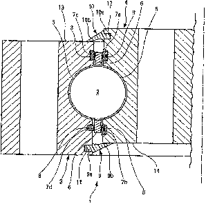
Figure 1 shows a partial axial-section view of a slewing
ring according to the present invention.
Detailed description of embodiments of the invention
As can be seen in the figure, in known manner, a slewing
ring 1 comprises: - rolling elements 2 (in this example ball
elements 2),- two concentric rings 3, 4 (one inner 3 and one
outer 4), in steel, mobile in rotation relative to one
another and forming a raceway 5 for ball elements 2, and - a
retainer 6 in steel arranged between the two rings 3, 4,
extending in the axial direction of slewing ring 1 either
side of the ball elements 2, being integral in rotation with
the latter and holding them regularly spaced apart in the
raceway 5. Also, the slewing ring 1 comprises contact
elements 7a,7b,7c,7d made in a non-ferrous material,
polyamide in this case, for example polyamide-6,6. Each
contact element 7a,7b,7c,7d is arranged between two members
formed by retainer 6 and one of the two rings 3,4,

CA 02478454 2004-08-23
3
The contact ring prevents any direct contact between these two
members 3,4;6, and is fixed to one of these two members 3,4;6
and comes into contact with the other.
Here the slewing ring 1 contains four contact elements
(contact rings) 7a,7b,'7c,7d :
- two 7a,7b are arranged between the retainer 6 and the outer
ring 4, prevent any direct contact between these two members
4,6, and are fixed to the outer ring 4 and come into contact
with retainer 6; and
- two 7c,7d are arranged between retainer 6 and inner ring 3,
prevent any direct contact between these two members 3,6, and
are fixed to the inner ring 3 and come into contact with
retainer 6.
As can be seen, the contact elements 7a,'7b attached to
the outer ring 4 are arranged in axial direction on either
sides of the raceway 5, as well as the contact elements 7c,7d
which are attached to inner ring 3.
This substantially symmetrical arrangement of the four
contact elements 7a,7b,7c,7d in relation to raceway 5 provides
perfect equilibrium of slewing ring 1 with absolutely no point
of contact between retainer 6 and either one of the two rings
3,4. This particular configuration is of particular interest
for slewing ring 1 whose rolling elements 2 describe a circle
of large diameter (for example at least 1m, even 1.5m or
over), and especially for rings used to orient devices
subjected to strong pressures such as the slewing ring 1 used
to direct blades in relation to the rotor of a wind turbine
nacelle according to wind force.
In the present example, the contact elements 7a,7b,7c,7d
are circular rings force fitted into corresponding grooves 8
made in concentric rings 3,4. As can be seen in the figure,
the straight section of these circular rings may be
trapezoidal, rectangular or semi-circular. The circular rings
are made of a compact material, i.e. non-porous. Preferably
they are made of a single piece.
In conventional manner the slewing ring 1 also includes
seals to retain the lubricant within the housing defined by

CA 02478454 2004-08-23
4
the two rings 3, 4 and in which the ball elements 2 and
retainer 6 are confined.
Slewing ring 1 may therefore include in particular lipped
seals denoted 9, 10 in figure 1, each comprising a base
9a,10a, inserted in a corresponding notch 11,12 of respective
ring 3, 4, and a lip 9b,10b bearing upon a corresponding
transverse surface 14,13 of the other ring 4,3.
Evidently, the present invention is not limited to the
above-described embodiment.
It would be possible for example to have contact elements
solely between the inner ring and the retainer or between the
outer ring and the retainer, although this would give the
present invention much lesser efficacy.
It would also be possible not to have any contact element
(contact ring) on either side of the raceway (in axial
direction).
It would also be possible for the contact elements to be
fixed to the retainer.
It would also be possible for the contact elements to be
made of any polymer material other than polyamide, for example
of polytetrafluoroethylene or polyimide. These contact
elements could also be made of non-ferrous metal, for example
a copper or bronze alloy.
It would also be possible to use other fixation means for
the contact elements depending upon the constituent materials:
they could be fixed chemically (bonded for example),
metallurgically (welded or brazed for example) or mechanically
(clipped or bolted for example).
It would also be possible to use rolling elements other
than ball elements, for example rollers.

Representative Drawing
A single figure which represents the drawing illustrating the invention.
Administrative Status

2024-08-01:As part of the Next Generation Patents (NGP) transition, the Canadian Patents Database (CPD) now contains a more detailed Event History, which replicates the Event Log of our new back-office solution.

Please note that "Inactive:" events refers to events no longer in use in our new back-office solution.

For a clearer understanding of the status of the application/patent presented on this page, the site Disclaimer , as well as the definitions for Patent , Event History , Maintenance Fee  and Payment History  should be consulted.

Event History

Description Date
Letter Sent 2024-02-23
Letter Sent 2023-08-23
Common Representative Appointed 2019-10-30
Change of Address or Method of Correspondence Request Received 2018-03-28
Grant by Issuance 2008-11-18
Inactive: Cover page published 2008-11-17
Pre-grant 2008-08-22
Inactive: Final fee received 2008-08-22
Notice of Allowance is Issued 2008-04-25
Letter Sent 2008-04-25
Notice of Allowance is Issued 2008-04-25
Inactive: IPC removed 2008-04-21
Inactive: Approved for allowance (AFA) 2008-03-12
Amendment Received - Voluntary Amendment 2007-11-16
Inactive: S.30(2) Rules - Examiner requisition 2007-06-11
Inactive: IPC from MCD 2006-03-12
Application Published (Open to Public Inspection) 2005-02-27
Inactive: Cover page published 2005-02-27
Letter Sent 2005-01-25
Inactive: Single transfer 2005-01-06
Inactive: First IPC assigned 2004-12-31
Inactive: Courtesy letter - Evidence 2004-10-12
Inactive: Filing certificate - RFE (English) 2004-10-08
Letter Sent 2004-10-05
Application Received - Regular National 2004-10-04
Request for Examination Requirements Determined Compliant 2004-08-23
All Requirements for Examination Determined Compliant 2004-08-23

Abandonment History

There is no abandonment history.

Maintenance Fee

The last payment was received on 2008-08-14

Note : If the full payment has not been received on or before the date indicated, a further fee may be required which may be one of the following

  • the reinstatement fee;
  • the late payment fee; or
  • additional fee to reverse deemed expiry.

Patent fees are adjusted on the 1st of January every year. The amounts above are the current amounts if received by December 31 of the current year.
Please refer to the CIPO Patent Fees web page to see all current fee amounts.

Owners on Record

Note: Records showing the ownership history in alphabetical order.

Current Owners on Record
DEFONTAINE
Past Owners on Record
DANIEL TERVE
DIDIER CHATRY
Past Owners that do not appear in the "Owners on Record" listing will appear in other documentation within the application.
Documents

To view selected files, please enter reCAPTCHA code :


To view images, click a link in the Document Description column (Temporarily unavailable). To download the documents, select one or more checkboxes in the first column and then click the "Download Selected in PDF format (Zip Archive)" or the "Download Selected as Single PDF" button.

List of published and non-published patent-specific documents on the CPD .

If you have any difficulty accessing content, you can call the Client Service Centre at 1-866-997-1936 or send them an e-mail at CIPO Client Service Centre.

({010=All Documents, 020=As Filed, 030=As Open to Public Inspection, 040=At Issuance, 050=Examination, 060=Incoming Correspondence, 070=Miscellaneous, 080=Outgoing Correspondence, 090=Payment})


Document
Description 
Date
(yyyy-mm-dd) 
Number of pages   Size of Image (KB) 
Description 2004-08-22 4 218
Abstract 2004-08-22 1 24
Claims 2004-08-22 2 75
Drawings 2004-08-22 1 26
Representative drawing 2005-01-31 1 18
Description 2007-11-15 5 213
Claims 2007-11-15 2 55
Acknowledgement of Request for Examination 2004-10-04 1 185
Filing Certificate (English) 2004-10-07 1 168
Courtesy - Certificate of registration (related document(s)) 2005-01-24 1 105
Reminder of maintenance fee due 2006-04-24 1 112
Commissioner's Notice - Application Found Allowable 2008-04-24 1 165
Courtesy - Patent Term Deemed Expired 2024-04-04 1 561
Commissioner's Notice - Maintenance Fee for a Patent Not Paid 2023-10-03 1 540
Correspondence 2004-10-14 1 25
Fees 2006-08-21 1 34
Fees 2007-08-16 1 37
Correspondence 2008-08-21 1 24
Fees 2008-08-13 1 34
Fees 2009-08-09 1 63
Fees 2016-05-01 1 24
Maintenance fee payment 2017-06-25 1 24