Note: Descriptions are shown in the official language in which they were submitted.
CA 02478814 2004-09-10
WO 03/078134 PCT/DK03/00191
1
Process for the production of a polymer layer of a
flexible offshore pipe and a flexible unbonded offshore
i e
Field of the invention
The present invention relates to a process for the
production of a polymer layer of a flexible offshore
pipe. The invention also relates to a process for the
production of a flexible offshore pipeline comprising a
polyethylene containing polymer layer, e.g. an inner
liner. The invention also concerns a flexible offshore
pipe comprising a polymer layer obtainable according to
the process.
Background of the invention
Flexible offshore pipes comprising a tube-formed inner
liner and at least one reinforcement layer are generally
used for the transportation of oil and gas products over
long distances and often at elevated temperatures, such
as above 60 C or more.
Offshore pipes are also used for injection of chemicals
into a sub-sea drilled well e.g. connected between a
host oil platform and a sub-sea satellite installation.
Offshore pipes must be capable of operating at high
pressures, and the pipes should be resistant to
chemicals and water, including seawater. Furthermore
such offshore pipes should be flexible so that they can
be spooled onto a drum or reel.
Offshore pipes are normally very long, so-called risers
often several hundred meters long and so-called flow-
lines often several kilometres long. They are laid on
SUBSTITUTE SHEET (RULE 26)
CA 02478814 2004-09-10
WO 03/078134 PCT/DK03/00191
2
the seabed, typically subjected to high pressures and
pressure differences along the pipeline. When the
pipeline is transporting oil or gas, the pipelines may
be exposed to temperatures substantially above 60 C. The
offshore pipes should therefore be capable of operating
at high temperatures and high pressures.
Offshore pipes generally comprise one or more tube-
formed barrier layers including an inner liner and at
lo least one reinforcing layer. The inner liner is the
innermost polymer layer, which in known offshore pipes
also constitutes a barrier layer, and which is exposed
to a fluid, e.g. oil transported in the pipeline. In
most situations, the pipeline also comprises an outer
sheath providing a barrier to the outer environment such
as seawater. The pipe normally comprises one or more
reinforcing layers between the inner liner and the outer
sheath, and some pipes also comprise a reinforcing layer
inside the pipe, called a carcass. The carcass prevents
collapse of the inner liner and provides mechanical
protection to the inner liner. Some pipes also comprise
one or more intermediate polymer layers.
The inner liner should be chemically stable and
mechanically strong even when subjected to high
temperatures. Furthermore, the inner liner should be
manufactured in one piece since repair, welding or other
types of connecting methods are not acceptable for inner
liners in offshore pipelines. The inner liner is
therefore normally produced by continuous extrusion of a
polymer. A number of polymers are presently used for the
production of inner liners, such as Polyamide-11 (PA-
11), polyethylene (PE) and Polyvinylidene diflouride
(PVDF).
SUBSTITUTE SHEET (RULE 26)
CA 02478814 2004-09-10
WO 03/078134 PCT/DK03/00191
3
These materials shall fulfil the combined requirements
of e.g. heat stability, resistance to crude oil,
seawater, gases, mechanical fatigue, ductility,
strength, durability and processability. The inner liner
s material is normally selected on a case-to-case basis
after careful investigation of the conditions for the
planned installation. Here, cross-linked polyethylene
may in many cases prove to fulfil the requirements.
Additionally, the interest in use of inner liners in
corrosive applications with high concentrations of
carbon dioxide and/or hydrogen sulphides is increasing.
Furthermore, polyamides are susceptible to hydrolysis
and aliphatic polyketones are also susceptible to
is degradation at elevated temperatures. However, the
permeability of gases increases with temperature, and
polyethylene has a relatively high permeability to
gases. Thus permeation of gases like methane, carbon
dioxide and hydrogen sulphide may in some cases be
prohibitive for use of cross-linked polyethylene inner
liners at high temperatures.
In EP 487 691 it has been suggested to use an inner
liner of cross-linked polyethylene. An inner liner with
such cross-linked material has shown to be highly
improved compared to inner liners of the similar non-
cross-linked (thermoplastic) material.
In order not to degrade the material, the process in the
prior art of producing an inner liner is carried out in
two steps, first the material in non-cross-linked form
is manufactured by extrusion, and afterwards the
material is cross-linked. When the material is cross-
linked, it is only to some degree possible to change its
shape without degrading the material.
SUBSTITUTE SHEET (RULE 26)
CA 02478814 2004-09-10
WO 03/078134 PCT/DK03/00191
4
The cross-linking step is often very cumbersome and time
and space demanding. EP 487.691 describes the cross-
linking step of silanized polyethylene with reference to
the figures. The pipeline is first manufactured by
extrusion of the inner layer of polyethylene, followed
by metal armouring and outer sheathing. The entire
multilayer pipe structure is mounted with end fittings,
and the flexible pipe is connected to a device for
circulating water in the inner liner tube. The water is
heated to about 92-98 C and circulated using pumps. The
time of cross-linking is between 48 and 120 hours
followed by a cooling step for about 20 hours.
By this process, it is necessary to manufacture the
entire pipe before making the actual cross-linking of
the inner liner. In case of a quality problem of the
inner liner, it appears impractical to make the entire
pipe without assuring final properties of the cross-
linked inner liner. The patent describes both the use of
a Sioplas process involving peroxide-activated grafting
of the vinylsilane onto the polyethylene in a separate
compounding step, and the Monosil process with in-situ
silane grafting of polyethylene. It is preferred to use
a dibutyltindilaurate (DBTDL) as cross-linking
accelerator and a density of the polyethylene above 931
kg/m3, preferably over 940 kg/m3.
The required properties for the other polymer layers,
intermediate layer(s) and outer layer are much similar
to the required properties of the inner liner.
A number of methods of producing PE based covers for
cables are known e.g. as disclosed in US 4528155 and US
3868436, by extrusion of PE comprising a heat
activatable peroxide, followed by subjecting the cover
SUBSTITUTE SHEET (RULE 26)
CA 02478814 2006-10-02
to heat e. g. by steam or pressurized Nitrogen to thereby
initiate the cross-linking thereof.
Summary of the invention
5
It is desirable to provide a process for the production of a
cross-linked polymer layer for a flexible offshore pipe, which
process can be used for long lerigths of tubes, and which
process results in a high degree of cross-linking even if the
tube has a relatively thick wall.
It is also desirable to provide a process for the production of
a polymer layer of an offshore pipe having a length of at least
50 meters by extrusion of a polyethylene based polymer followed
by cross-linking, which method is faster and less space
demanding than known processes.
It is further desirable to provide a process for the production
of a flexible unbonded offshore pipe comprising a tube-formed
inner liner, which comprises extrusion of a polyethylene based
polymer inner liner followed by cross-linking, which method is
faster and less space demanding than known processes.
Therefore, in accordance with an aspect of the invention, there
is provided a method for the production of a flexible unbonded
pipe comprising one or more polymer layers, comprising the step
of shaping at least one of said one or
CA 02478814 2004-09-10
5a
more polymer layers from a polymer material by extrusion into or
onto a supporting unit in an extrusion station and cross-linking
said extruded polymer material, said polymer material comprising a
polyethylene and a peroxide for providing a cross-linking of the
polymer material, said peroxide having an activation temperature
substantially above, preferably at least 5 C above, more
preferably at least 10 C above the temperature of the polymer
material during the extrusion thereof, said cross-linking of said
extruded polymer material being carried out by exposing the
extruded polymer material to electromagnetic waves, selected from
the group consisting of infrared radiation and microwave.
Therefore, the invention also provides a flexible unbonded
offshore pipe obtainable by the method of the present invention.
Disclosure of the invention
The process of the present invention may in principle be used for
the production of any one of the polymer layers of a flexible
offshore pipe. These polymer layers are
CA 02478814 2004-09-10
WO 03/078134 PCT/DK03/00191
6
also referred to as tube formed polymer layers. A
flexible offshore pipe is also denoted an unbonded pipe,
which means that the pipe comprises two or more layers
which are not bonded along their entire length so that
the individual layers can slide with respect to each
other. This feature gives the offshore pipe a high
flexibility.
The process of the invention is particularly useful for
the production of flexible unbonded offshore pipes
comprising tube-formed polymer layer(s), e.g. an inner
liner, an intermediate polymer layer and/or a cover
layer. The process is specifically useful for the
manufacturing of so-called endless offshore pipes, i.e.
pipelines having a length of 50 m or more.
The process for the production of a polymer layer
according to the invention comprises the step of shaping
a polymer material by extrusion into or onto a
supporting unit in an extrusion station and in a
subsequent step cross-linking the extruded polymer
material to obtain hardening and high strength of the
material.
The polymer material comprises a polyethylene and an
amount of peroxide for cross-linking of the
polyethylene. The peroxide should preferably have an
activation temperature substantially above, preferably
at least 5 C above, and more preferably at least 10 C
above the temperature of the polymer material during the
extrusion thereof. The term "substantially above the
temperature of the polymer material during the extrusion
thereof" means that the peroxide should not be activated
during the extrusion.
The peroxide is thus chosen to have an activation
SUBSTITUTE SHEET (RULE 26)
CA 02478814 2004-09-10
WO 03/078134 PCT/DK03/00191
7
temperature above the temperature of the polymer
material during extrusion to avoid that activated
peroxide will induce cross-linking during extrusion.
During extrusion, cross-linking of the polymer is highly
undesired as it will complicate the extrusion and result
in clogging of the equipment. In one embodiment of the
invention, the extrusion and the cross-linking steps are
carried out in an in-line process, including passing the
extruded polymer material directly through a cross-
lo linking zone with means to activate the peroxide to
obtain cross-linking. Thus, the cross-linking step is
carried out in a separate step subsequent to the
extrusion step.
In one embodiment, the polymer layer is passed from the
extruder to the cross-linking zone with less than 25 C
average intermediate cooling, such as less than 10 C
average intermediate cooling, such as essentially no
intermediate cooling. The term "average cooling" means
average through the thickness of the polymer layer.
Thus, the surface of the polymer layer may be cooled
down more than the middle of the material. In one
embodiment, it is desired that the cooling of the
surface of the polymer layer does not exceed 40 C,
preferably the cooling of the surface of the polymer
layer does not exceed 20 C from the extruding zone to
the cross-linking zone.
The polymer material, which is shaped during the
process, comprises polyethylene. In a preferred
embodiment, polyethylene constitutes the major part of
the polymer material, and only minor parts of other
polymers are present. For some purposes, it is preferred
that polyethylene is the only polymer material present.
Also mixtures of polyethylene with different or varying
properties may be used according to the invention, e.g.
SUBSTITUTE SHEET (RULE 26)
CA 02478814 2004-09-10
WO 03/078134 PCT/DK03/00191
8
mixtures of two or more polyethylenes with different
densities. By selecting polyethylenes with different
densities and optionally other polymers and additives it
is possible to design a polymer composition with desired
properties.
Polyethylene is often used for inner liners for offshore
flexible pipes at operational temperatures up to about
600C. Primarily the high density polyethylene (HDPE),
lo which has a substantially linear chain structure, is
used. The HDPE has a somewhat higher stiffness and
mechanical strength than other polyethylene types. Also,
it has a higher crystallinity and therefore a lower
permeability to gases. The typical HDPE used for inner
liners is pipe grades with a density of 945 to 965 kg/m3,
and preferably around 950 kg/m3. Preferred polyethylene
to be used according to the invention has a density
above 920 kg/m3, such as e.g. from 940 kg/m3 and up to
about 965 kg/m3, that provides polyethylene which has the
best properties for use as inner liners according to the
invention. The inner liner may in one embodiment be a
co- extruded layer comprising two or more sub layers
e.g. of PE with different densities. The co-extruded
materials may e.g. be cross-linked in one cross-linking
step using electromagnetic waves according to the
invention.
In general, to obtain the best possible properties it is
preferred that the polymer material comprises at least
50 o by weight, preferably at least 70 o by weight, more
preferably at least 85 a by weight of polyethylene.
The polymer material may in one embodiment include up to
about 40 o by weight, such as up to about 20 0 or
preferably up to about 10 o by weight of additional
polymer(s) other than polyethylene. The additional
SUBSTITUTE SHEET (RULE 26)
CA 02478814 2004-09-10
WO 03/078134 PCT/DK03/00191
9
polymer(s) may e.g. be selected from the group
consisting of thermoplastics such as thermoplastic
elastomers including block copolymer such as SEBS, SBS,
SIS, TPE-polyether-amide, TPE-polyether-ester, TPE-
urethanes, TPE PP/NBR, TPE-PP/EPDM, TPE-vulcanisates and
TPE-PP/IIR; rubbers such as butadiene rubber, isoprene
rubber, nitril rubber, styrene-butadiene rubber and
urethane rubber; polyolefins such as polypropylene and
polybutylene including its isomers; liquid crystal
Zo polymers; polyesters; polyacrylates; polyethers;
polyurethane; thermplastic vulcanisates; and Liquid
Silicone Rubber.
The polyethylene material typically contains minor
amounts of additives like pigments, heat stabilisers,
process stabilisers, metal deactivators, flame-
retardants and/or reinforcement fillers. It is
preferred to keep the amount of such additives low to
reduce the risk of blistering and stress induced
cracking. The reinforcement fillers may e.g. include
glass particles, glass fibres, mineral fibres, talcum,
carbonates, mica, silicates, and metal particles.
In one embodiment, the* polymer layer is a co-extruded
layer comprising two or more co-extruded polymer sub
layers of equal or different material compositions.
These co-extruded sub layers may preferably be cross-
liked in one step, whereby the material sub layers will
bind to each other. Thus, in one embodiment the polymer
layer comprises co-extruded sub layers in the form of an
innermost sub layer of a polyethylene material with a
higher amount of fillers, and an outermost sub layer of
a polyethylene material with a lower amount of fillers.
According to the invention the cross-linking of the
polymer material is initiated by peroxide serving as a
SUBSTITUTE SHEET (RULE 26)
CA 02478814 2006-10-02
radical-former when activated. A specific peroxide decomposes
at a specific temperature (the activation temperature of the
peroxide). The preferred peroxides according to the invention
5 also decompose if they are exposed to certain electromagnetic
wavelengths, e.g. microwave or infrared light. The
decomposition causes the peroxide to release radical-formers
which induce cross-linking in the polymer material. The
temperature during the extrusion is typically between 145 to
10 200 C. The temperature during extrusion is selected to keep
the polymer material in a molten state. Cross-linking of the
polymer is undesired during extrusion as it will make the
extrusion more difficult. Thus, it is preferred to select a
peroxide having an activation temperature above 145 C or even
above 150 C. Preferably the selected peroxide has an
activation temperature which is substantially above such as at
least 1 C, and preferably at least 5 to 10 C: above the
temperature of the polymer material during the extrusion.
Consequently it is preferred to select a peroxide with a higher
activation temperature such as butylcumylperoxide,
dicumylperoxide, Trigonox 145BTM 2,5-dimethyl hexane 2,5-di-t-
butyl peroxide, bis(t-butylperoxy isopropyl)benzene, t-butyl
cumyl peroxide, di-t-butyl peroxide, 2,5-dimethyl hexine-3 2,5-
di-t-butyl pero or a hydroperoxide, e.g. butylhydroperoxide.
According to the invention the pe:roxide may be activated by
exposing the extruded polymer material to electromagnetic
waves, selected from the group consisting of infrared radiation
and microwave.
The peroxide is added to the polyethylene before extrusion.
The peroxide may be added in solid state as powder or
granulate. Alternatively the peroxide may be added in liquid
form. When the peroxide is added in liquid form, it is
preferred that the polyethylene is
CA 02478814 2004-09-10
WO 03/078134 PCT/DK03/00191
11
present with about 90% of granules and about 100 of
powder.
In general, the amount of peroxide in the polymer
composition should preferably be at least 0.1 o by
weight of the polymer composition, such as between 0.2
and 3 o by weight of the polymer, more preferably up to
about 2 0 or even more preferably up to about 1.5 o by
weight of the total polymer composition including
peroxide.
To obtain a satisfactory cross-linking of the polymer
material when using infrared radiation for activating
peroxide, it is preferred that the polymer composition
contains peroxide from 0.1 to 1.0 o by weight, and
preferably from 0.2 to 0.8 % by weight of the total
polymer.
The process of the invention comprises the step of
exposing the extruded polymer material to
electromagnetic waves selected from the group consisting
of infrared radiation and microwave, i.e. in the range
of about 0.5 m to 0.5 m. In one embodiment, the
extruded polymer material is exposed to electromagnetic
waves for a sufficient time to thereby raise the
temperature of the extruded polymer material at least to
the activation temperature of the peroxide. The
necessary time for exposing thereby depends largely on
the type of peroxide, the thickness of the material, the
intensity and wavelength of the electromagnetic
radiation, as well as the initial temperature of the
extruded polymer material at its entrance into the
cross-linking zone.
According to the invention the extruded polymer material
is passed to a cross-linking zone to initiate the cross-
SUBSTITUTE SHEET (RULE 26)
CA 02478814 2004-09-10
WO 03/078134 PCT/DK03/00191
12
linking. The cross-linking is initiated by activating
the peroxide by use of electromagnetic waves, such as
infrared radiation.
in one embodiment, the cross-linking is activated by
exposing the extruded polymer to electromagnetic waves
with a wavelength measured in vacuum of between 0.5 m
and 20 cm, such as between 0.8 m and 10 cm, such as
between 1.0 m and 1 cm. In one embodiment the cross-
linking is activated by exposing the extruded polymer to
electromagnetic waves with a wavelength measured in
vacuum of between 2.0 m and 1000 m.
in one preferred embodiment, the cross-linking is
activated by exposing the extruded polymer to infrared
radiation. In one embodiment using infrared radiation to
activate the peroxide it is desired that the melted
polymer material from the extruder is sufficiently
transparent to allow the infrared radiation to penetrate
the polymer material to induce the cross-linking.
Thereby even thick layers of extruded polymer can be
cross-linked very fast. The preferred embodiment
comprises use of polyethylene heated above the
crystalline melting temperature T. (approximately 125-
130 C) to obtain a glass clear and amorph polymer
material. Under such conditions the activation of
peroxide and cross-linking of the polymer material will
appear within seconds. Generally the cross-linking
appears relatively fast when using infrared radiation
activated peroxides, and the polymer material may be
cross-linked within 60 seconds. According to the
invention the supporting unit may comprise means that
reflects infrared radiation, such as a metal-foil or
other reflecting foils. The polymer composition itself
may also include particles which may reflect the
electromagnetic waves, e.g. metal particles or glass
SUBSTITUTE SHEET (RULE 26)
CA 02478814 2004-09-10
WO 03/078134 PCT/DK03/00191
13
beads. However, in one embodiment the amount of
additives in the polymer composition should be kept at
low level, e.g. below 10 o by volume such as below 5 0
by volume in order to maintain the transparent
appearance of the polymer composition.
In one embodiment using microwave to activate the
peroxide, the amount of additives in the polymer
composition may be higher, e.g. above 5 o by volume or
io even above 10 % by volume because the polymer layer to
be cross-linked need not be transparent. Therefore in
situation where the polymer layer is not sufficiently
transparent to be cross-linked using infrared radiation
as a peroxide activator, the polymer layer may
preferably be treated with microwave or with a mixture
of microwave or infrared radiation.
In one embodiment using infrared radiation to activate
the peroxide it is desired that the infrared radiation
comprises wavelengths in the range 0.5-10 m, more
preferably at least 50 0 of the energy applied by
infrared radiation is applied in the form of infrared
radiation with wavelength in the range 0.5-10 m, such
as in the range 0.8-6.0 m, such as in the range 1.0-5.0
m.
Thus, it has surprisingly been found that the polymer
layer can be cross-linked sufficiently fast to avoid
deformation due to gravity forces of the melted and
extruded layer even when the layer has a large thickness
and thereby a high weight. The thickness of such
offshore flexible pipe polymer layers may e.g. be about
4 mm or more, such as 6 mm or more, such as 8 mm or
more, such as 10 mm or more, such as 12 mm or more, such
as 14 mm or more, such as 16 mm or more, such as 18 mm
or more.
SUBSTITUTE SHEET (RULE 26)
CA 02478814 2004-09-10
WO 03/078134 PCT/DK03/00191
14
It is particularly preferred that the cross-linking is
activated by application of infrared radiation, where
the infrared radiation comprises wavelengths
corresponding to the absorption peaks for the polymer
material. Thus, in one embodiment the maximum intensity
of the infrared radiation is in the range 0.0-10 m,
such as in the range 1.0-7.0 m, such as in the range
3.0-7.0 m. Thereby the heating has shown to be very
fast in the whole thickness of the layer even when the
thickness is above 4mm or thicker such as above 10 mm,
such as 12 mm or more, such as 14 mm or more, such as 16
mm or more, such as 18 mm or more.
In one embodiment, wherein the cross-linking is
activated by application of infrared radiation it has
been found that a very fast cross-linking with at high
degree of cross-linking can be obtained when using
infrared radiation comprising wavelengths corresponding
to the absorption peaks for the polymer material.
Preferably the maximum intensity of the infrared
radiation is in the range 0.7-10 m, such as in the
range 1.5-7.0 pm, such as in the range 3.0-7.0 m. In
particular, it is desired in this embodiment that the
infrared radiation comprises wavelengths in the ranges
3.3-3.6 m and/or 6.7-6.9 m which are absorption peaks
for polyethylene.
The infrared radiation source usable to activate the
peroxide may be any type of IR lamp which radiates a
suitable amount of infrared radiation, preferably with
wavelengths as stated above. In one embodiment an
infrared lamp with electromagnetic waves in the interval
0.5-5.0 m and with a peak around 1.2 m is used. The
infrared radiation source is preferable placed in the
cross-linking zone in such a way that all parts of the
SUBSTITUTE SHEET (RULE 26)
CA 02478814 2004-09-10
WO 03/078134 PCT/DK03/00191
extruded polymer material are exposed to infrared
radiation.
In one embodiment, the electromagnetic wave generating
5 means in the cross-linking zone is preferably arranged
in such a way that the polymer material is subjected to
electromagnetic waves from all sides or angles in the
cross-linking zone. For instance when the polymer
material has a circular cross section, the
10 electromagnetic wave generating means is placed all
around the circumference of the cross-section to obtain
the best possible heating effect on the polymer
material.
15 The time for performing the cross-linking in the cross-
linking zone in the heat activated embodiment depends
mainly on the thickness of the polymer layer, the type
of peroxide used including its activating temperature,
and the method used for activating the peroxide in the
cross-linking zone. In some applications, the cross-
linking time may be relatively long, e.g. 10 minutes or
even longer, but in order to optimize the in-line
process and the space occupied by the cross-linking
zone, the time for performing the cross-linking should
preferably be adjusted to be about the time for
extruding 0.05 to 2 m, preferably 0.2 to 1 m of the
polymer material. This adjustment may be performed by
regulating the application of heat, the selection of
type of peroxide, and the thickness of the extruded
polymer. Also the extrusion velocity may be adjusted.
In one embodiment, the process according to the
invention includes the use of infrared heaters or
microwaves as heating means, the extruded material is
subjected to a heat treatment in the cross-linking zone
for up to about 600 seconds and preferably for 5 to 120
SUBSTITUTE SHEET (RULE 26)
CA 02478814 2004-09-10
WO 03/078134 PCT/DK03/00191
16
seconds, and more preferably for 10 to 60 seconds.
in a preferred embodiment, the extruded polymer material
is subjected to a heat treatment in the cross-linking
zone at a temperature above 145 C and preferably at a
temperature between 150 and 200 C to ensure activation of
the peroxide. The optimal temperature depends on the
type of peroxide and can easily be found by a few
experiments.
When infrared heating lamps are used according to the
invention, this has the advantage that the peroxide may
be activated simultaneously by infrared light and heat.
Hereby an excellent and rapid cross-linking can be
obtained.
Compared with prior art techniques, it is possible to
obtain a relatively high degree of cross-linking using
the process according to the invention. In one
embodiment, the degree of cross-linking obtained is 75
to 90 %, and preferably the degree of cross-linking is
80 to 85 o according to ASTM D 2765. Thus, cross-linking
may appear in both the amorphous and crystalline phase
of the polymer material.
In a preferred embodiment of the process according to
the invention, the pressure in the cross-linking zone is
raised above ambient pressure. By increasing the
pressure in the cross-linking zone, formation of bubbles
and irregularities in the polymer material can be
avoided. The pressure is preferably raised to 1.5 bars
above ambient pressure, more preferably 2 bars above
ambient pressure, and typically the pressure in the
cross-linking zone is between 2.5 and 10 bars.
In order to avoid undesired deformation or reactions in
SUBSTITUTE SHEET (RULE 26)
CA 02478814 2004-09-10
WO 03/078134 PCT/DK03/00191
17
the extruded polymer material, it is in one embodiment
preferred that the extruded polymer material enters the
cross-linking zone immediately after extrusion or no
later than about 5 or even 2 minutes after extrusion. By
passing the extruded polymer material from the extruder
to the cross-linking zone, the temperature of the
polymer material may be kept close to the extrusion
temperature at the entrance to the cross-linking zone,
which means that the necessary amount of energy for
activating the peroxide is as low as possible.
Generally, it is preferred that the temperature of the
polymer material at the entrance to the cross-linking
zone is at least 100 C, preferably at least 120 C and
even more preferably at least 140 C. The entrance is
defined as the place between the extruder and the cross-
linking zone where the temperature of the polymer
material is lowest.
Moreover, in order to optimise the properties of the
extruded product and avoid deformation it is preferred
that the velocity of the extrusion of the polymer
material is approximately equal to the velocity of the
extruded polymer passing through the cross-linking zone,
and the velocity is preferably between 0.2 to 2
m/minute, and more preferably between 0.5 and 1.0
m/minute.
Preferably the extruded polymer material from the cross-
linking zone is cooled to ambient temperature, e.g. the
polymer material may be cooled in a cooling zone with
water or air.
The supporting unit may in principle be any kind of
supporting means which supports the polymer material as
it passes out from the extruder. The supporting unit
onto which the polymer material may be extruded may
SUBSTITUTE SHEET (RULE 26)
CA 02478814 2004-09-10
WO 03/078134 PCT/DK03/00191
18
simply be a mandrel, net or hollow wire. The supporting
unit onto which the polymer material may be extruded may
preferably be a tube-formed unit, such as a calibrating
device (calibrator). Such calibrator is generally known,
from the art of extruding inner liners for flexible
unbonded offshore pipes without inner reinforcing
layer(s) (carcass). A calibrator may e.g. calibrate the
outer dimension of the pipe or tube shaped polymer layer
using vacuum suction onto a solid surface e.g. metal
surface, which surface may preferably be wetted with
water for lubrication.
Thus, in a preferred embodiment the polymer layer is an
inner liner of a flexible unbonded offshore pipe without
carcass, and the inner liner is extruded into a
supporting unit, preferably in the form of a calibrator.
In a preferred embodiment of the process according to
the invention, the supporting unit is a reinforcement
material, and preferably a reinforcement layer of a
flexible unbonded offshore pipe.
The supporting unit may e.g. be in the form of a
carcass, in which case the polymer layer is an inner
liner of a flexible unbonded offshore pipe and the
polymer material is extruded onto the carcass to form
the inner liner.
Where the polymer layer is an intermediate layer of a
flexible unbonded offshore pipe, the supporting unit may
preferably be in the form of a pressure armour, and the
polymer material is extruded onto the pressure armour.
Where the polymer layer is an outer cover of a flexible
unbonded offshore pipe, the supporting unit may
preferably be in the form of a tensile armour, and the
SUBSTITUTE SHEET (RULE 26)
CA 02478814 2004-09-10
WO 03/078134 PCT/DK03/00191
19
polymer material is extruded onto the tensile armour.
Please observe that the term "outer cover" does not
exclude that further armouring layer or layers are
applied around the outer cover, but in general this term
should be interpreted to mean that the outer cover is
the outermost pipe shaped polymeric layer.
In one embodiment, it is preferred that the supporting
unit material is a metallic material, preferably shaped
as a carcass, a pressure armour or a tensile armour of
metallic material. The metallic material may preferably
be capable of reflecting infrared radiation from the
infrared radiation source or optionally heat from the
heating means in the cross-linking zone, thereby
increasing the effect of the infrared radiation or
heating on the polymer material. This reflective effect
will lead to faster and more effective activation of the
peroxide and cross-linking of the polymer material.
When extruding a polymer layer onto a supporting unit in
the form of a carcass or another armour, it is in one
embodiment preferred that a secondary layer e.g. a tape
or film layer is applied onto the armour prior to the
application of the polymer layer. Thereby undesired
deformation of the polymer layer due to the shape of the
surface of the armour which may e.g. - be made from
profiles engaged into each other, may be avoided. In one
embodiment, wherein the supporting unit is an armour
layer and this secondary layer comprises a tape applied
onto the armour and the polymer composition is extruded
onto this tape, it is preferred that the tape has a
reflecting surface reflecting the infrared radiation or
heat applied in the cross-linking zone. The tape may
e.g. comprise a metallized surface. The reflecting
surface of the tape may preferably be capable of
reflecting at least 50 0 of the infrared radiation or
heat applied to the tape when using infrared light or
SUBSTITUTE SHEET (RULE 26)
CA 02478814 2004-09-10
WO 03/078134 PCT/DK03/00191
infrared heating or microwave heating.
In one embodiment, the polymer layer may comprise a
secondary layer below the polymer layer, said secondary
5 layer preferably having a reflective surface reflecting
the electromagnetic waves applied in the cross-linking
zone. The reflective surface of the secondary layer may
preferably be capable of reflecting at least 50 % of the
not adsorbed electromagnetic waves, which in practice
10 means that the secondary layer is capable of reflecting
at least 50 0 of the electromagnetic waves irradiated at
the surface.
One embodiment, where the supporting unit is an armour
15 layer, comprises a secondary layer such as a foil
applied onto the armour, and the polymer composition is
extruded onto this secondary layer. The secondary layer
may e.g. be a permeation barrier e.g. as described later
on for liquid and gas, such as methane, hydrogen
20 sulphides and carbondioxides. Thereby armour layers
placed on the outer side of the secondary layer are
protected from such aggressive gasses which may be
transferred in the pipe.
In one embodiment, the tube formed polymer article
obtained by the process according to the invention is an
inner liner of the offshore pipe.
The cumbersome and time-consuming cross-linking of the
inner liner as well as the outer cover and/or
intermediate layer or layers of a flexible pipe product,
as described in EP 487.691, can be overcome by the
present invention, in particular by initiating the
cross-linking in-line (or on-line) with the extrusion of
the inner liner. By in-line is simply meant 'in the same
continuous process step'. As a result the liner material
SUBSTITUTE SHEET (RULE 26)
CA 02478814 2004-09-10
WO 03/078134 PCT/DK03/00191
21
completes the cross-linking within the cross-linking
zone without any further treatment, and e.g. before the
final multilayer pipe structure is completed.
By the present invention, cross-linking of the inner
liner may be terminated prior to the making of the metal
armouring and outer sheath and the end fittings. This is
advantageous for several reasons. Quality control is
made earlier in the production cycle and necessary
lo corrections can be made earlier. Also, by the present
invention it is possible to cut samples from the end of
the cross-linked inner liner for measurements of the
degree of cross-linking. It is not possible to do this
on a finished pipe. If this should be done on a pipe
according to the EP 487.691, it would require cutting
off a section of the pipe and establishing a new end
fitting, which is costly and time consuming.
In one embodiment according to the process of the
invention, polyethylene and other ingredients for the
polymer composition including the peroxide and
accelerator may be melted and homogenised in an extruder
which feeds the polymer melt into a distributor and a
tool, either a crosshead tool or a pipe tool. With a
crosshead tool, a metal carcass may be fed into the
centre of the crosshead tool, and the polymer may be
extruded around this metal cylinder. The carcass may be
at ambient temperature (cold) or preheated to avoid
rapid quenching of the polymer melt. The inner liner
thickness may typically be 4 to 10 mm when using a
carcass, and somewhat larger, typically 6 to 16 mm
without a carcass. However, the thickness of the inner
liner may differ from the above typical values,
depending on the contemplated use of the pipe. For some
uses a thickness below 4 or 6 mm is sufficient, such as
01 BC.]c'Y"17'1 1'M ~, I-8lr4=1
SUBSTITUTE SHEET (RULE 26)
CA 02478814 2004-09-10
WO 03/078134 PCT/DK03/00191
22
down to 2 mm. For other uses thickness above 10 or 16
mm, e.g. 18 mm or more may be required.
After extrusion of the pipe using a crosshead tool into
which the carcass is fed, the polymer melt forms a
cylindrical object around the carcass. In one
embodiment, the extruded pipe may directly after the
extrusion be subjected to the radiation with
electromagnetic waves and thereby be cross-linked.
Alternatively, the inner liner may be made without a
metallic carcass e.g. using pipe tool (or a crosshead
tool), and in this case the extruded object may pass
through a calibrator as described above.
After the extrusion, the extruded polymer tube may be
passed into a cross-linking zone as described. An
example of an in-line cross-linking equipment is
outlined in Figure 1 and described below.
After cooling of the cross-linked polymer layer e.g.
using water, the pipe passes out of the cooling chamber
and is optionally dried, typically by a wipe-off device
and blowing with air. Then a drawing device, typically a
caterpillar device, draws the pipe forward. The polymer
inner liner may here be cooled below the softening
point, which may prevent the caterpillar belts from
causing mechanical damage to the inner liner. After the
caterpillar, the pipe is spooled on a drum, reel or
turntable. The metal armouring and the subsequent
extrusion of the outer sheath are normally performed in
separate steps.
The invention also relates to a method for the
production of a flexible unbonded offshore pipe
comprising one or more polymer layers (inner liner,
SUBSTITUTE SHEET (RULE 26)
CA 02478814 2004-09-10
WO 03/078134 PCT/DK03/00191
23
intermediate layer or layers and outer cover) in the
form of a tube-formed polymer layer wherein at least one
of the polymer layers is produced according to the
process defined in the claims.
In one embodiment, the method comprises the steps of
i) providing a carcass
ii) applying a secondary layer in the form of a
lo gas permeation barrier layer onto the carcass,
iii) applying an inner liner in the form of a
polymer layer according to the process as
described above, wherein the polymer material
is applied onto a supporting unit,
iv) applying one or more reinforcing layers onto
the inner liner.
In another embodiment, the method comprises the steps of
i) providing an inner liner in the form of a
polymer layer according to the process as
described above, wherein the polymer material
is applied into a supporting unit,
ii) applying a secondary layer in the form of a
gas permeation layer onto the inner liner
iii) applying one or more reinforcing layers onto
the inner layer.
The secondary layer may e.g. be IR reflective as
described above.
The gas permeation barrier layer may e.g. be in the form
of a foil, such as a metal foil, or in the form of a
polymer. The permeation barrier layer means a layer of a
material which provides a higher permeation barrier,
such as 50 o higher, such as 100 % higher such as 500%
SUBSTITUTE SHEET (RULE 26)
CA 02478814 2004-09-10
WO 03/078134 PCT/DK03/00191
24
higher barrier than the inner liner against hydrogen
sulphides, and preferably also against methane and
carbondioxides. In one embodiment, the permeation
barrier layer is a polymer layer. The permeation barrier
layer is preferably thinner that the inner liner such as
up to about 50 0, such as up to about 20 0 of the
thickness of the inner liner. The permeation barrier
layer and the inner liner may e.g. be co-extruded and
optionally cross-linked in one step of irradiation with
lo electromagnetic waves e.g. IR.
In one embodiment, the permeation barrier layer is a
foil which is wound or bent around the carcass or a
removable support tool. The foil may preferably be
applied with overlapping edges to thereby form a
complete layer. Thereafter the polymer layer may be
applied using the method as defined in the claims,
including cross-linking using electromagnetic waves.
During the cross-linking the foil will adhere or be
bonded to the polymer layer, and simultaneously the
overlapping edges will be held closely together to form
a high permeation barrier layer. In one embodiment, the
permeation barrier layer is essentially impermeable to
one or more of the gasses hydrogen sulphides, methane
and carbondioxide preferably all of the gasses at a
partial pressure for the respective gasses of 0.03 bar
or more, such as 0.1 bar or more, such as ibar or more,
such as 10 bars or more. In one embodiment the
permeation barrier layer is essentially impermeable to
sulphides at a partial pressure of 0.03 bars or more,
such as 0.1 bars or more, and to methane at a partial
pressure of 1 bar or more, such as 10 bars.
Furthermore, the invention relates to a flexible
unbonded offshore pipe comprising at least one polymer
layer, said polymer layer being obtainable using the
SUBSTITUTE SHEET (RULE 26)
CA 02478814 2006-10-02
process as defined in the claims.
The flexible unbonded offshore pipe may have any shape e.g. as
known from WO 00/36324 and US 6,085,799. One or more of the
5 tube-formed polymer layers, e.g. the inner liner, intermediate
layer or layers and/or outer cover, may be produced using the
process of the invention.
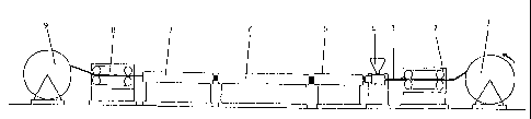
Fig. 1 is a sketch of a production line usable in the process
10 of the invention.
Fig. 1 is a sketch of a production line for the production of
an inner liner for an offshore pipeline. A carcass, i.e. a
metal armouring 3, of an offshore pipeline is unwound from a
15 pay-off device 1 and passes through a caterpillar device 2. An
extrusion device 4 extrudes a polyethylene inner liner onto the
carcass, and the extruded inner liner passes together with the
carcass directly to a cross-linking zone 5, where it is
subjected to a treatment with electromagnetic waves, e.g. with
20 infrared radiation. From the cross-linking zone 5 it passes
into a first cooling zone 6, wherein the heated polyethylene
inner liner is cooled. From the first cooling zone 6, it
passes into a second cooling zone 7, wherein it is further
cooled. From the second cooling zone 7, it passes through a
25 second caterpillar device 8 and further to a take up device 9
onto which it is wound.
The present invention includes passing the extruded polymer
material directly through a cross-linking zone. In the cross-
linking zone, the material is subjected to an intensive
heating, e.g. with infrared radiation. In the cross-linking
zone, the activation means e.g. infrared lamps are arranged to
surround the extruded
CA 02478814 2004-09-10
WO 03/078134 PCT/DK03/00191
26
polymer material so as to subject the polymer material
to infrared radiation from all sides or angles. The
extruded polymer material preferably enters the cross-
linking zone immediately after extrusion or no later
than 2 minutes after extrusion.
The velocity of the extrusion of the polymer material is
approximately equal to the velocity of the extruded
polymer passing through the cross-linking zone. A
preferred velocity is between 0.2 to 2 m/minute,
preferably between 0.5 and 1.0 m/minute.
From the crosshead tool, the pipe preferably passes into
a first chamber, wherein it is subjected to infrared
i5 light or heat, e.g. from infrared sources.
The pipe should preferably be in the first chamber for a
sufficient time to initiate cross-linking of the inner
liner. The necessary time can be determined by cross-
linking thin samples for various periods of time. Based
on this time and the knowledge of the extrusion line
speed, the necessary minimum length of the first chamber
can be calculated.
After being treated in a first cross-linking chamber,
the inner liner may optionally be introduced into a
second chamber, where the inner liner is cooled
optionally by water cooling.
After being treated in a first cross-linking chamber and
optionally a second cooling chamber, the inner liner may
be introduced into a third chamber, where the inner
liner is further cooled.
The third chamber may preferably be a traditional
cooling chamber with water suspension or water spraying
SUBSTITUTE SHEET (RULE 26)
CA 02478814 2004-09-10
WO 03/078134 PCT/DK03/00191
27
onto the pipe containing the inner liner. Typically, tap
water at ambient temperature is used or recirculating
water connected to a heat exchanger. Time and thus
length of the chamber should preferably be sufficient to
cool down the pipe to below approximately 60 C to ensure
sufficient strength of the inner liner so that it may be
handled by the caterpillar belts without any damage.
The total length of the cross-linking and cooling
chambers should preferably for practical reasons be kept
below 100 meters in length. On the other hand, the
cooling sections in the prior art processes are
typically several tens of meters in length. The total
length of a line for prior art extrusion of large
dimension flexible pipes is well above one hundred
meters.
Please observe that all though the first chamber, the
second chamber and the third chamber, respectively, are
sometimes referred to as one chamber, these chambers
each represent a treatment, which in practice may be
conducted in two or more physically separated treatment
chambers. Consequently, the first chamber represents a
first step of the treatment of the extruded inner liner,
the second chamber represents a second step of the
treatment of the extruded inner liner, and the third
chamber represents a third step of the treatment of the
extruded inner liner.
However, according to the invention the cooling of the
polymer material may optionally be effected in one step
in one chamber as one cooling treatment.
One effect of cross-linking polyethylene is that the
material may be used at higher operating temperatures
without being deformed due to excellent chemical and
SUBSTITUTE SHEET (RULE 26)
CA 02478814 2004-09-10
WO 03/078134 PCT/DK03/00191
28
mechanical properties. It is expected that the operating
temperature can be increased from approximately 60 C to
approximately 90 C for typical offshore applications.
A few simple methods of characterising the cross-linking
are probe penetration, hot set and the degree of cross-
linking determined,by decaline extraction.
The hot set test, as specified in IEC 811-2-1, clause 9
and as used in several electrical cable standards as
e.g. VDE 0273 and IEC 502, measures the mechanical
elongation (set) of a test specimen at 200 C under a
specified load. The lower the value is, the higher the
degree of cross-linking. If not cross-linked at all, the
sample will simply flow away. It further measures a cold
set after removal (a residual set). A well cross-linked
sample will have essentially no cold residual set.
The degree of cross-linking is measured by decaline
extraction according to the ASTM D 2765 standard
prescribing a 6-hour extraction. The degree of cross-
linking is simply the relative weight of unextractable
material. By experience, values for cross-linked
polyethylene are normally in the 75a to 80% range. The
inventors' experience with new improved process is that
the degree of cross-linking is often higher, in the 80
to 90o range. This method of measuring the degree of
cross-linking suffers from the disadvantage of being
destructive, because it is necessary to cut out a piece
of the material. Thus this method is unsuitable for
quality control of the cross-linking step of inner
liners.
The probe penetration test measures the relative o of
penetration of a 1 mm diameter cylindrical probe into a
sample of the material at a given temperature under a
given load. The inventors have found suitable parameters
SUBSTITUTE SHEET (RULE 26)
CA 02478814 2004-09-10
WO 03/078134 PCT/DK03/00191
29
to be a load of 300 mN for samples of 2 to 3 mm
thickness, and heating by 5 C/minute from 25 to 150 C.
This method has the advantage of being non-destructive.
For cross-linked polyethylene with over 70o degree of
cross-linking, the penetration at 140 C is typically
less than 250. Un-cross-linked polyethylene has 100%
penetration, and partially cross-linked samples give
intermediate penetration values. We suggest the use of
30o as maximum penetration indicative of sufficient
cross-linking, corresponding to approximately 65% degree
of cross-linking.
Example
On a full-scale production line an inner liner of
polyethylene is extruded on a self-interlocking carcass
of 6" inner diameter (15.2 cm). The outer diameter of
this steel carcass is approximately 16.7 cm. The carcass
is fed into the centre of a crosshead tool. In this
tool, the polyethylene melt is distributed in a pipe
type tool and upon the exit of the crosshead is drawn
onto the carcass in approx. 6 mm thickness at a line
speed of 0.48 to 0.55 meters/minute.
The extruder is a conventional polyethylene single screw
extruder with a 120 mm screw diameter and an L/D ratio
of 30, with a standard screw. The extrusion process is
found not to be temperature sensitive. The temperature
setting on the heating zones of the extruder and head
ranges from 150 to 165 C, and melt temperature is
typically 160 C.
The polyethylene is a mixture of 90a HD-PE, grade 5621
from Basell and 10o UHW-PE powder, grade HE 2591 from
c..K... . ,. . .
Borealis. The additives are a mixture of 0.45o DYBP from
SUBSTITUTE SHEET (RULE 26)
CA 02478814 2004-09-10
WO 03/078134 PCT/DK03/00191
Degussa and 0.40o Irganox XP621 from Ciba. DYBP (2,5-
dimethyl hexine-3 2,5-di-t-butyl peroxide) is the
peroxide which induces cross-linking of the PE. DYBP is
activated by infrared radiation (DYBP may also be
5 activated by heat at 180 C, thus the temperature in the
extruder should not at any time exceed 175 C). Irganox is
an antioxidant. The material is fed into the extruder as
a premix.
10 After the extrusion the pipe passes through an IR oven
with a capacity of 75 kW. Residence time in the oven is
30-60 seconds.
After this the carcass with inner liner is cooled with
15 water and led through a caterpillar.
Samples are cut from the inner liner. 2 mm thick
sections are cut from the innermost and outermost part
of the liner, respectively.
The degree of cross-linking and hot set at 200 C is
determined on these samples.
Test results:
Gel content o: 76.3
Hot set o: 35
Set -5
SUBSTITUTE SHEET (RULE 26)