Language selection

Search

Patent 2479447 Summary

Third-party information liability

Some of the information on this Web page has been provided by external sources. The Government of Canada is not responsible for the accuracy, reliability or currency of the information supplied by external sources. Users wishing to rely upon this information should consult directly with the source of the information. Content provided by external sources is not subject to official languages, privacy and accessibility requirements.

Claims and Abstract availability

Any discrepancies in the text and image of the Claims and Abstract are due to differing posting times. Text of the Claims and Abstract are posted:

  • At the time the application is open to public inspection;
  • At the time of issue of the patent (grant).
(12) Patent Application: (11) CA 2479447
(54) English Title: ROLLER CAM MECHANISM AND DRIVE ASSEMBLY WITH POSITIVE RETRACTION
(54) French Title: MECANISME EXCENTRIQUE A CYLINDRE ET MECANISME D'ENTRAINEMENT AVEC RETRACTION POSITIVE
Status: Deemed Abandoned and Beyond the Period of Reinstatement - Pending Response to Notice of Disregarded Communication
Bibliographic Data
(51) International Patent Classification (IPC):
  • B26F 1/40 (2006.01)
  • B30B 1/40 (2006.01)
  • F16H 25/18 (2006.01)
(72) Inventors :
  • CHUN, VICTOR L. (United States of America)
  • MOUZAYA, JOSEPH (United States of America)
(73) Owners :
  • DANLY IEM, DIVISION OF CONNELL LIMITED PARTNERSHIP
(71) Applicants :
  • DANLY IEM, DIVISION OF CONNELL LIMITED PARTNERSHIP (United States of America)
(74) Agent: MACRAE & CO.
(74) Associate agent:
(45) Issued:
(22) Filed Date: 2004-08-30
(41) Open to Public Inspection: 2005-05-05
Availability of licence: N/A
Dedicated to the Public: N/A
(25) Language of filing: English

Patent Cooperation Treaty (PCT): No

(30) Application Priority Data:
Application No. Country/Territory Date
10/703,203 (United States of America) 2003-11-05

Abstracts

English Abstract


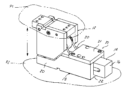
A roller cam mechanism and driver assembly which features a positive
retraction
cam elements comprised of auxiliary rollers and side plate slots which
cooperate upon failure of
a retraction spring compressed by advance of a tooling slide to cause positive
retraction of a
tooling slide.


Claims

Note: Claims are shown in the official language in which they were submitted.


Claims
1. A roller cam and driver assembly comprising:
a driver assembly adapted to be attached to press platen, said driver assembly
having a portion being formed with a ramp surface;
a roller cam mechanism including a slide mounted in a slide mounting body
adapted to be attached to a press platen for motion in a direction transverse
to motion of a press
in which said slide mounting body is installed, said roller cam mechanism
including a main roller
rotatably mounted to said slide so as to be engaged with said driver ramp
surface upon closing of
press platens;
said roller cam mechanism also including a retraction spring compressed by
advancing of said slide and causing said slide to be retracted upon withdrawal
of said driver;
said roller cam mechanism further including mating retraction cam elements on
each of said slide and driver assembly respectively, positively causing
retraction of said slide
upon withdrawal of said driver assembly.
2. An assembly according to claim 1 wherein said mating retraction cam
elements comprise an auxiliary roller aligned with said main cam roller and a
corresponding cam
surface on said driver assembly pulling on said retraction roller to
positively retract said slide.
3. An assembly according to claim 1 wherein said roller cam mechanism
includes a pair of retraction cam elements each comprising an outboard
retraction auxiliary roller

aligned with said main cam roller and on one side thereof, and said driver
includes retraction cam
surfaces pulling on a respective outboard retraction auxiliary rollers upon
separation of said press
platens.
4. An assembly according to claim 3 wherein said retraction spring is a
helical spring disposed within a lengthwise space in said slide, one end of
said spring engaged by
said slide, on opposite end of said spring engaged with a pin fixed to said
slide mounting body so
that said spring is compressed. by advancing movement of said slide.
5. An assembly according to claim 3 wherein said slide has a pair of upright
spaced apart lugs, said lugs formed with aligned bores receiving an axle shaft
mounting said
main cam roller, said axle shaft having opposite ends each protruding past a
respective lug and
mounting a respective outboard retraction auxiliary roller.
6. An assembly according to claim 5 wherein said driver including side plates
mounted to each side of said portion formed with said ramp surface, and formed
with angled cam
slots located to receiving a respective outboard retraction auxiliary roller.
6

Description

Note: Descriptions are shown in the official language in which they were submitted.


CA 02479447 2004-08-30
1 ROLLER CAM MECHANISM AND DRIVE ASSEMBLY
2 WITH POSITIVE RETRACTION
3
4
Bac~ound of the Invention
6 This invention concerns roller cams which are widely used in die presses to
carry
7 out such functions as piercing holes into a workpiece which is engaged in
the press by forming
8 dies. Roller cams utilize a roller engaged by a driver which is fixed to a
press platen, which
9 roller is mounted to a slide so as to be advanced by a ramp surface as the
driver is advanced by
the platen motion. Sliding cams are not operated at angles other than
horizontal due to friction,
11 and are more bulky and costly than roller cams.
12 A spring is used to return the slide in roller cams. However, if stripping
is
13 necessary as when piercing the workpiece with punch tooling, the tool must
be withdrawn by the
14 force of the spring while the workpiece is held. Mechanical springs
normally are not strong
enough to do this, necessitating the use of more powerful devices such as
nitrogen gas springs.
16 Also, if the spring fails, the roller cam will malfunction as there is no
force
17 generated in that event available to return the slide.
18 It is an object of the present invention to provide a roller cam which
provides a
19 failsafe return of the slide even when part stripping is necessary.
21 Summary of the Invention
22 The above object and other objects which will become apparent upon a
reading of
23 the following specification and claims are achieved by a roller cam
mechanism including a slide
24 mounting a main roller between two upwardly projecting lugs. The main
roller is mounted on a

CA 02479447 2004-08-30
1 support axle shaft which projects beyond each lug to comprise overhung ends.
An auxiliary
2 roller is mounted on each overhung axle end, which rollers in turn are
received in angled slots
3 formed in each of a pair of side plates included in the driver assembly. The
auxiliary rollers are
4 pulled by a surface on a respective side plate slot as the upper platen is
retracted so as to
positively return the slide to its retracted position if a return spring also
included is not effective
6 to do so.
7 The slide is normally returned by the return spring which is received in a
8 lengthwise extending space in the slide, and captured between a fixed pin
and a retainer so as to
9 be compressed when the slide is advanced by the driver ramp surface engaging
the main roller.
Thus, only in the event the spring breaks or develops insufficient force to
strip a
11 tool from a workpiece, auxiliary rollers are engaged to positively return
the slide when the press
12 platen mounting the driver assembly is raised.
13
14 Description of the Drawings
I 5 Figure I is a pictorial view of a roller cam and engaged driver assembly
according
16 to the present invention.
17 Figure 2 is a side pictorial view of the roller cam and driven assembly,
shown
18 broken away along its longitudinal axis.
19 Figure 3 is an exploded pictorial view of certain components of the roller
cam
mechanism and driver assembly shown in Figures l and 2.
21 Figure 4 is a pictorial partially exploded view from another angle of the
roller cam
22 mechanism and driver assembly shown in Figures 1 and 2.
2

CA 02479447 2004-08-30
1 Figure 5 is a pictorial view of the roller cam mechanism and driver assembly
of
2 Figures 1-4 mounted in a press for an angled motion.
3
4 Detailed Description
In the following detailed description, certain specific terminology will be
6 employed for the sake of clarity and a particular embodiment described in
accordance with the
7 requirements of 35 USC 112, but it is to be understood that the same is not
intended to be
8 limiting and should not be so construed inasmuch as the invention is capable
of taking many
9 forms and variations within the scope of the appended claims.
Referring to the drawings, a roller cam mechanism 10 adapted to be mounted on
a
11 press upper platen P 1 is shown, engaged with a driver assembly 12 adapted
to be mounted on a
12 press lower platen P2 and driven thereby to an extended position to
accomplish a piercing or
13 other secondary operation on a workpiece (not shown).
14 The roller cam 10 includes a slide 14 mounting the tooling (not shown)
which is
attached at the end of an elongated portion 16 thereof. A slide mount 18
includes a pair of side
16 walls 20 and a bottom wall 22 defining a guide way 19 for receiving the
slide 14 and guiding the
17 same during stroking thereof. A top plate 21 confines the elongated tool
mounting portion 16 of
18 the slide 14.
19 The driver assembly 12 includes a member 24 housing a main ramp surface 25
aligned with a central cam main roller 28 to engage the same.
21 The main cam roller 28 is rotatable on the center part of an axle shaft 30
received
22 in aligned bores 34 in a pair of upright spaced part lugs 32.
3

CA 02479447 2004-08-30
1 The axle shaft 30 has reduced diameter ends 36 each of which protruding past
the
2 outside of a respective one of the lugs 32 and receiving an outboard
retraction auxiliary cam
3 elements comprising rollers 38 held thereon by a retainer 40. Each auxiliary
cam roller 38 is
4 engaged by a slot 42 in a respective side plate 44 attached to the cam
driver 24.
The slide 14 has a lengthwise elongated space 46 formed therein which receives
a
6 helical compression spring 48. Spring 48 is engaged at one end by a cross
pin 50 fixed extending
7 between side walls 20 of the slide mount 18, passing through a slot 52 in
the slide 14.
8 Thus, when the slide 14 is advanced by the ramp 25 forcing the main cam
roller
9 28 to the right as viewed in Figure 2, the spring 48 is compressed.
As the driver assembly 12 is raised, the compressed spring 48 forces the slide
14
11 back to the left.
12 If the spring 48 is broken or has insufficient force to strip the tooling
out of the
13 workpiece, the outboard retraction auxiliary rollers 38 engage one of the
respective slot walls 43
14 and forcibly raise the same, causing the slide 14 to be positively
retracted.
4

Representative Drawing
A single figure which represents the drawing illustrating the invention.
Administrative Status

2024-08-01:As part of the Next Generation Patents (NGP) transition, the Canadian Patents Database (CPD) now contains a more detailed Event History, which replicates the Event Log of our new back-office solution.

Please note that "Inactive:" events refers to events no longer in use in our new back-office solution.

For a clearer understanding of the status of the application/patent presented on this page, the site Disclaimer , as well as the definitions for Patent , Event History , Maintenance Fee  and Payment History  should be consulted.

Event History

Description Date
Application Not Reinstated by Deadline 2008-09-02
Time Limit for Reversal Expired 2008-09-02
Inactive: Office letter 2008-03-27
Letter Sent 2008-03-27
Deemed Abandoned - Failure to Respond to Maintenance Fee Notice 2007-08-30
Inactive: IPC from MCD 2006-03-12
Application Published (Open to Public Inspection) 2005-05-05
Inactive: Cover page published 2005-05-04
Inactive: Office letter 2004-12-29
Letter Sent 2004-12-24
Inactive: First IPC assigned 2004-12-13
Inactive: Single transfer 2004-12-02
Inactive: Courtesy letter - Evidence 2004-10-19
Inactive: Filing certificate - No RFE (English) 2004-10-18
Filing Requirements Determined Compliant 2004-10-18
Application Received - Regular National 2004-10-18

Abandonment History

Abandonment Date Reason Reinstatement Date
2007-08-30

Maintenance Fee

The last payment was received on 2006-06-14

Note : If the full payment has not been received on or before the date indicated, a further fee may be required which may be one of the following

  • the reinstatement fee;
  • the late payment fee; or
  • additional fee to reverse deemed expiry.

Please refer to the CIPO Patent Fees web page to see all current fee amounts.

Fee History

Fee Type Anniversary Year Due Date Paid Date
Application fee - standard 2004-08-30
Registration of a document 2004-12-02
MF (application, 2nd anniv.) - standard 02 2006-08-30 2006-06-14
Registration of a document 2008-01-11
Owners on Record

Note: Records showing the ownership history in alphabetical order.

Current Owners on Record
DANLY IEM, DIVISION OF CONNELL LIMITED PARTNERSHIP
Past Owners on Record
JOSEPH MOUZAYA
VICTOR L. CHUN
Past Owners that do not appear in the "Owners on Record" listing will appear in other documentation within the application.
Documents

To view selected files, please enter reCAPTCHA code :


To view images, click a link in the Document Description column. To download the documents, select one or more checkboxes in the first column and then click the "Download Selected in PDF format (Zip Archive)" or the "Download Selected as Single PDF" button.

List of published and non-published patent-specific documents on the CPD .

If you have any difficulty accessing content, you can call the Client Service Centre at 1-866-997-1936 or send them an e-mail at CIPO Client Service Centre.


Document
Description 
Date
(yyyy-mm-dd) 
Number of pages   Size of Image (KB) 
Descriptions 2005-05-05 4 166
Abstract 2004-08-30 1 16
Claims 2004-08-30 2 74
Abstract 2004-08-30 4 166
Drawings 2004-08-30 5 123
Representative drawing 2005-04-07 1 12
Cover Page 2005-04-18 1 36
Filing Certificate (English) 2004-10-18 1 168
Courtesy - Certificate of registration (related document(s)) 2004-12-24 1 105
Reminder of maintenance fee due 2006-05-02 1 112
Courtesy - Abandonment Letter (Maintenance Fee) 2007-10-25 1 173
Correspondence 2004-10-18 1 27
Correspondence 2004-12-23 1 11
Correspondence 2008-03-27 1 7