Note: Descriptions are shown in the official language in which they were submitted.
CA 02479475 2007-05-31
BAGLESS VACUUM CLEANER AND
DIRT COLLECTION ASSEMBLY
Technical Field
The present invention relates generally to the floor care equipment field and,
more particularly, to an upright or canister vacuum cleaner equipped with a
dirt
collection assembly.
Background of the Invention
Bagless vacuum cleaner technology has long been known in the art.
Japanese Patent Applications 56-136642 and 56-136650, both published in 1981,
disclose an upright vacuum cleaner with a dust collection chamber that
removably
connects to an opening of the main unit to facilitate user convenience during
the
emptying of the cleaner. A removable filter fills an opening at the bottom of
the
dust chamber and serves to separate dust from air drawn through the vacuum
cleaner by the fan and motor assembly.
The present invention relates to an improved dirt collection assembly for an
upright or canister vacuum cleaner.
Summary of the Invention
In accordance with the purposes of the present invention as described herein,
a
vacuum cleaner includes a housing, a suction generator and a dirt collection
assembly.
The dirt collection assembly includes an inlet, an outlet and a concave air
deflector.
More specifically describing the invention, the dirt collection assembly
includes a
dirt cup having a sidewall and a bottom wall. The inlet is provided in the
bottom wall.
CA 02479475 2007-05-31
2
Further the dirt cup has an open top forming the outlet. A filter chamber is
provided
on the downstream side ofthe dirt cup and prefilter. An optional filter may be
provided in
the filter chamber. Additionally, the vacuum cleaner may also include a rotary
agitator held in
the housing.
In accordance with yet another aspect of the present invention, a dirt
collection assembly
is provided. That dirt collection assembly comprises a dirt cup having a
sidewall and a bottom
wall, an inlet in the dirt cup, an outlet in the dirt cup and a concave air
deflector The inlet is
provided in the bottom wall of the dirt cup. Additionally, a feed conduit
extends from the inlet
into the dirt cup. The concave air deflector is carried by the feed conduit.
The dirt collection assembly may further include a prefilter covering the
outlet.
In addition, the dirt collection assembly may include a filter chamber and a
filter in the
filter chamber. Both of these structtzes are. optional but when pmvided the
prefilter is positioned
between the dirt cup outlet and the filter chamber. Typically, the concave air
deflector
has a radius of curvature of between about 50 and about 100 mm.
In accordance with still another aspect of the present invention a method is
provided for
delivering air into a dirt collection vessel. The method comprises delivering
that air into
a dirt collection chamber formed in a dirt collection vessel along a
substantially
parabolic trajectory. This is done by deflecting the air off of a concave air
deflector.
Accordingly, in another aspect the present invention lies in a vacuum cleaner,
comprising a housing; a suction generator held in said housing; and a dirt
collection assembly held in said housing, said dirt collection assembly
including a
dirt cup having a sidewall, a bottom wall, an inlet in said bottom wall, an
outlet, a
prefilter covering said outlet, a concave air deflector, a filter chamber and
a filter
in said filter chamber.
In a further aspect, the present invention lies in a method of delivering air
into a dirt collection vessel, comprising delivering said air along a
substantially
parabolic trajectory into a dirt collection chamber including a dirt cup
having a
sidewall, a bottom wall, in inlet in said bottom wall, an outlet, a prefilter
covering
said outlet, a concave air deflector, a filter chamber and a filter in said
filter
chamber.
CA 02479475 2007-05-31
2a
In the following description there is shown and described a preferred
embodiment of this invention simply by way of illustration of one of the modes
best
suited to carry out the invention. As it will be realized, the invention is
capable of other
different embodiments and its several details are capable of modification in
various,
obvious aspects all without departing from the invention. Accordingly, the
draw rigs
and descriptions will be regarded as illustrative in nature and not as
restrictive
CA 02479475 2007-05-31
3
Brief Description of the DrawingFigures
The accompanying drawing incorporated in and forming a part of this
specification, illustrates several aspects of the present invention, and
together with the
description serves to explain certain principles of the invention. In the
drawing:
Figure 1 is a schematical, elevational view illustrating a vacuum cleaner
incorporating the novel dirt collection assembly of the present invention;
Figure 2 is a schematical side elevational view of the vacuum cleaner shown in
Figure 1; and
Figure 3 is a partially cutaway, detailed perspective view of the dirt
collection
vessel.
Reference will now be made in detail to the present preferred embodiment of
the invention, an example of which is illustrated in the accompanying drawing.
Detailed Description of the Invention
The vacuum cleaner 10 generally comprises a housing including a nozzle
assembly 12 and a canister assembly 14. In the upright vacuum cleaner
illustrated in
Figures 1 and 2, the canister assembly 14 is pivotally connected to the nozzle
assembly
12. Of course, in a canister vacuum cleaner the nozzle assembly 12 would be
connected
to the canister assembly 14 through a wand assembly including a wand and a
flexible
hose.
The nozzle assembly 12 and canister assembly 14 of the upright vacuum cleaner
10 include a pair of rear wheels 16 and a pair of height adjustable front
wheels 18 for
supporting the weight of the vacuum cleaner. Additionally, the nozzle assembly
12
includes an agitator cavity 20 that receives a rotary agitator 22. An intake
port 24 is
provided in the back of the agitator cavity 20. The intake port 24 is in fluid
communication with a suction conduit 26 that extends at least partially
through both the
nozzle assembly 12 and the canister assembly 14. The canister assemblyl4
includes a
housing 28 including a cavity 30 for receiving and holding a dirt collection
assembly
generally designated by reference numeral 32. A control handle 34 is also
connected to
the housing 28 of the nozzle assembly 14.
CA 02479475 2007-05-31
4
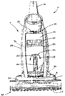
The dirt collection assembly 32 includes a dirt cup 36 including a side wa1138
and a bottom wall 40 that define a dirt collection chamber 42. An inlet 44 is
provided in
the bottom wall 40. A feed conduit 46 is in fluid communication with the inlet
44 and
extends at least partially into the dirt chamber 42. An air deflector 48 is
mounted on the
feed conduit 46 adjacent the open end 47 thereof by means of a bracket 50. As
illustrated, the deflector 48 has a concave configuration with a concavity
directed toward
the open end of the feed conduit 46.
Typically, the concave air deflector 48 has a radius of curvature of between
about 50
and about 100 mm and still more typically 75 and about 100 mm. It should also
be
appreciated that the dirt collection chamber 42 formed in the dirt cup 36 is
typically cylindrical
in shape. Further, both the feed conduit 46 and the air deflector 48 are
concentrically
positioned in the dirt collection chamber 42.
A prefilter 52, in the form of a mesh or screen, is received over or in and
encloses the
open top of the dirt cup 38. A filter 54, such as a filter cartridge with a
pleated filter media is
held in a ca.vity 56 foYrned in the filter chamber housing 58. A discharge
outlet 60 in the filter
chamber housing 58 is provided in fluid communication with a discharge conduit
62 formed in
the rear of the canister assembly 14. The discharge conduit 62 has an outlet
64 in fluid
communication with the internal chamber 66 in the canister assembly 14 that
houses the suction generator 68 comprising a fan and motor assembly. As
illustrated, the internal chamber 66 is divided by a partition 70 into an
inlet chamber 72 and an
exhaust chamber 74. The suction generator 68 bridges tlvs partition 70.
In operation, the rotary agitator 22 beats and brushes dirt and debris from
the nap of an
underlying carpet being cleaned. That ditt and debris becomes entrained in a
suction airstream
drawn into the intake port 24 by operation of the suction generator 68 (see
action armw A in
Figure 1). The airstream, entrained with dirt and debris is then drawn from
the suction
conduit 26 through the inlet 44 and into the feed conduit 46 (note action
arrows B in
Figures 1 and 2). Next, the airstream with entrained dirt and debris is drawn
through
the open end of the feed conduit 46 and is directed by the deflector 48
outwardly into
the dirt collection chamber 36 of the dirt cup 38. As a result of the action
of the
deflector 48, the airstream is dispersed in a substantially parabolic
trajectory or path
CA 02479475 2007-05-31
similar in shape to that of an open umbrella. The relatively heavy dirt and
debris
collects in the bottom of the dirt collection chamber 36 while the airstream,
now
devoid of this larger and heavier material, is drawn by the suction generator
68
through the passages 76 in the prefilter 52 (note action arrows C). The
airstream then
5 passes through the filter 54 where any remaining fine dirt and debris is
captured.
The now clean airstream is then drawn by the suction generator 68 from the
filter chamber 56 through the outlet 60 into the discharge conduit 62 (note
action
arrow D). The airstream then passes from the outlet 64 and is drawn into the
intake
chamber 72 of the suction fan cavity (note action arrow E).
The airstream then passes over the motor of the suction generator 68 and
advantageously provides cooling for the motor (note action arrow F). The
airstream is then exhausted from the discharge chamber 74 of the suction
generator cavity 66 through a final filter 78 and a group of exhaust ports 80
(note
action arrow G).
The foregoing description of the preferred embodiment of this invention
has been presented for purposes of illustration and description. It is not
intended
to be exhaustive or to limit the invention to the precise form disclosed.
Obvious
modifications or variations are possible in light of the above teachings. For
example, in the illustrated embodiment the dirt cup 36 and the combined filter
chatnber 56 and prefilter 52 are separately removable from the housing 28 of
the
canister assembly. In an alternative embodiment, they all may be removed
together. Further while a single agitator 22 is illustrated in Figure 2, it
should be
appreciated that the vacuum cleaner may include multiple agitators. In
addition,
while a "clean air" system is illustrated with the suction generator 68
downstream
from the dirt collection assembly 32, it should be appreciated that a "dirty
air"
system with the suction generator upstream from the dirt collection assembly
is
also contemplated. Further, while a dirt cup 38 is shown, a disposable bag
could
also be utilized in place of the dirt cup.
CA 02479475 2007-05-31
6
The embodiment was chosen and described to provide the best illustration
of the principles of the invention and its practical application to thereby
enable
one of ordinary skill in the art to utilize the invention in various
embodiments and
with various modifications as are suited to the particular use contemplated.
All
such modifications and variations are within the scope of the invention as
determined by the appended claims when interpreted in accordance with the
breadth to which they are fairly, legally and equitably entitled. The drawings
and preferred embodiment do not and are not intended to limit the ordinary
meaning of the claims and their fair and broad interpretation in any way.