Note: Descriptions are shown in the official language in which they were submitted.
CA 02479911 2004-09-20
WO 03/080943 PCT/AU03/00374
1
TITLE: GROUND LEVELLING APPARATUS
FIELD OF THE INVENTION
This invention relates to ground levelling apparatus.
In the earth moving industry, the term "cutting edge" is commonly used to
refer to a
wear member that is demountably bolted or otherwise on a working edge of an
implement (such as a grader blade or bucket) that cuts into the ground. In the
absence
of the wear member, the working edge itself would engage the ground. The wear
member is designed and positioned to engage the ground instead of the working
edge
of the implement.
In this specification, the term "cutting edge" is used in the same sense and
the term
"knife edge" is used to refer more particularly to the actual ground engaging
edge of
the cutting edge or, in a case where no separate cutting edge is provided, the
ground
engaging working edge of the implement itself
BACKGROUND OF THE INVENTION
There are a great many commercially available ground levelling machines,
including
such machines for use on farms. It would often not be economically justifiable
for
most farmers to own an industrial ground levelling machine such as a motor
grader.
Consequently, machines have been developed for towing behind agricultural
tractors
or mounting on other prime movers such as front end loaders.
In most circumstances, ground that has been levelled should be as free as
possible of
localised dips and rises. To this end ground levelling machines are designed
so that the
path of the blade in a horizontal direction remains as true as possible. A
prime mover
inevitably moves up and down as it traverses the ground and any implement
mounted
on the prime mover will move up and down with the prime mover. In fact, in the
case
of an implement that is hung out cantilever fashion over the front or back of
a prime
CA 02479911 2004-09-20
WO 03/080943 PCT/AU03/00374
2
mover, such movement will be exaggerated. US patent no. 4809449 discloses a
levelling apparatus of this kind, designed to be mounted on the lift arms of a
front end
loader.
One way of reducing the movement of a blade carried by the implement is to
suspend
the blade on a frame that is supported on ground wheels at its rear end. The
greater the
distance between the wheel and the blade, the less will be the degree of up
and down
movement of the blade. US patent no. 4236586 discloses a leveller with a blade
assembly mounted on such a frame.
In a set up in which such a frame is not used, the implement is commonly
mounted on
the prime mover by a mounting arrangement actuated by one or more hydraulic
rams.
Often the rams are controlled manually by the driver of the prime mover.
Nowadays,
however, the rams can be controlled automatically, using laser level
technology.
Manual control is cheaper but less reliable than automatic control.
With the development of more powerful tractors has come the possibility of
increasing
the blade length of ground levelling machines and hence the width of the swath
of
earth cut by the blade in a single pass. For example, levelling machines with
blades of
over 10 metres in length are now commercially available. Laser level
technology has
also made the use of longer blades more practicable. However, the use of
longer blades
has some disadvantages. First, any levelling machine with such a long blade is
likely to
be too heavy to be hung from the front or back of a prime mover. This is
particularly
so since the blade must be very stiff and will therefore be heavy, if it is to
remain
straight in use, The apparatus shown in the aforementioned US patent no.
4809449
would certainly be too heavy if it was provided with such a long blade. The
commercially available levelling machines having such long blades and known to
the
applicant are of the type in which the blade is mounted on a wheeled
supporting frame.
Second, the length of the blade is likely to cause difficulties in
transporting the
machine from one work place to another. One way of overcoming this problem is
to
provide a folding blade. One example of a long folding blade is shown in the
aforementioned US patent no. 4236586. However, the structure of a folding
blade is
CA 02479911 2004-09-20
WO 03/080943 PCT/AU03/00374
3
inherently likely to be less rigid and straight, and more complex and
expensive than a
one piece blade.
SUMMARY OF THE INVENTION
According to the invention there is provided ground levelling apparatus
arranged to be
drawn behind a prime mover and comprising an elongate ground engaging knife
edge
mounted on a carrier joined to a drawbar arrangement that can be connected to
the
prime mover, the drawbar arrangement being arranged to position the carrier so
that
the knife edge is level with a bottom portion of the carrier that is parallel
to the knife
edge and that bears on the ground as the apparatus is drawn over the ground by
the
prime mover.
According to one aspect of the invention the carrier is of right circular
cylindrical cross
section. Advantageously, the carrier is comprised essentially of a right
circular
cylindrical steel pipe.
In one form of the invention the knife edge is incorporated in a cutting edge
that is
mounted on the carrier.
In one form of the invention the bottom portion of the carrier is provided
with a wear
plate for bearing on the ground.
In one aspect of the invention the drawbar arrangement comprises hitch means
located
adjacent its forward end for pivotably connecting the drawbar arrangement to a
connection on the prime mover, the hitch means being such that carrier can
remain on
the ground under its own weight while the forward end of the drawbar
arrangement
undergoes a predetermined degree of pivotal movement in a vertical direction
about
the connection.
The distance between the knife edge and the connection on the prime mover is
advantageously at least 12, or preferably 15, times as great as the distance
between the
knife edge and the bottom portion of the carrier.
CA 02479911 2004-09-20
WO 03/080943 PCT/AU03/00374
4
In one form of the invention the knife edge is located between the bottom
portion of
the carrier and the connection on the prime mover.
In another aspect of the invention the carrier is joined to the drawbar
arrangement in
such manner as to allow the carrier to be moved relative to the drawbar
arrangement
between a first working position in which the carrier is disposed athwart the
direction
of motion of the drawbar arrangement in use, and a second working position in
which
the carrier is disposed substantially parallel to said direction of motion.
In one form of the invention the drawbar arrangement comprises a pair of
elongate
members each of which, when the apparatus is in use, projects forwardly from
the
carrier when the drawbar arrangement is in the first working position and has
a front
end and a rear end, the elongate members being spaced apart adjacent their
rear ends
where they are each pivotably joined to the carrier and being pivotably joined
together
adjacent at their front ends, means being provided to enable the elongate
members to
move into a disposition in which they are close together and close to the
carrier when
the drawbar arrangement is in the second working position.
In one form of the invention one of the elongate members is adjustable,
advantageously telescopically, in length.
BRIEF DESCRIPTION OF THE DRAWINGS
The invention is further discussed with reference to the accompanying drawings
in
which:
Figure 1 is a somewhat schematic sectional side elevation of one example of a
ground levelling apparatus according to the invention;
Figures 2 and 3 are plan views of the apparatus showing respectively a drawbar
thereof in an unfolded (working) position and a folded position, used in
transporting
the apparatus;
CA 02479911 2004-09-20
WO 03/080943 PCT/AU03/00374
Figures 4 and 5 are views of the apparatus from the front, on arrow A in
Figure
2, showing a ground wheel arrangement, used for transporting the apparatus, in
an
unfolded (working) position and a folded position respectively;
5
Figures 6 and 7 are side views, on Arrows B and C in Figures 3 and 2
respectively, of parts of the apparatus;
Figures 8 and 9 are views from below and above, on Arrows D and E
respectively in Figure 1, of further parts of the apparatus;
Figure 10 is a view from above, also on Arrow E in Figure 1 of yet another
part
of the apparatus but with a plate 120 removed: and
Figure 11 is a schematic side view of a wheel arrangement that can be fitted
to
the apparatus.
DESCRIPTION OF EMBODIMENTS SHOWN IN THE DRAWINGS
For the sake of avoiding repetition, in this specification the use of the
phrase "in the
present example" or words to the same effect is intended to indicate that what
is being
described is by way of illustrative example and that there is no intention
that the scope
of the invention be limited thereto unless this appears from the context. On
the other
hand, there is no intention that, in the absence of a phrase of the same kind,
the scope
of the invention is to be limited by any matter described unless this appears
from the
context.
Referring first to the example shown in Figure 1, the levelling apparatus 10
comprises
a cutting edge 12 mounted on a mounting beam 14 in the form of a right
circular
cylindrical steel pipe. The beam is an example of what is otherwise herein
called a
carrier. The beam is of essentially the same length as the cutting edge so
that the beam
supports the cutting edge along the entire length of the latter. The cutting
edge is
substantially conventional except that it, and the beam, may be rather longer
than
CA 02479911 2004-09-20
WO 03/080943 PCT/AU03/00374
6
usual. In the present example the length of each is in excess of 12 metres.
The
applicant believes that cutting edges of this length are not commercially
available as a
single piece so, for economy, the cutting edge 12 may be made up of, say, five
shorter
pieces, each of 2.4 metres length.
The cutting edge 12, or the shorter pieces of which it is made up, have each a
knife
edge 12a that engages the ground
Mounting brackets 16 are welded to the beam along its length to act
collectively as a
seat for seating the cutting edge 12. Each bracket 16 is provided with a
vertical slot
(not visible in the drawing) that mates with a hole in the cutting edge 12,
Mounting
bolts pass through the mating slots and holes and receive nuts 18 by means of
which
the cutting edge 12 is fixed, in conventional fashion, on the beam. The slots
allow for
accurate alignment of the cutting edge.
A bar 20 of hardened steel is welded to the bottom of the beam, extending the
full
length thereof. The beam rests on the bar when the beam is on the ground. The
bar 20
also acts as a skid on which the beam is able to slide when the beam is drawn
over the
ground as will be described.
Care must be taken when welding the skid bar 20 to the beam to ensure that,
after
welding, the skid bar is straight. Similarly, when the cutting edge 12 is
being mounted
on the beam, care must be taken to ensure that the knife edge 12a is straight
and
parallel to the skid bar 20. The beam must be sufficiently strong and rigid to
ensure
that it does not sag substantially or bend in use.
End plates 22, 24 are welded to the ends of the beam. Each end plate has a
lower edge
26 that projects forwardly from the bottom of the beam in a horizontal
direction. The
edge slides over the ground in use. The end plates help to reduce spillage of
soil past
the ends of the cutting edge when the apparatus is in use. The front edge of
one end
plate 24 is provided with two recesses 28, 30 located one above the other. The
purpose
of these recesses is described below.
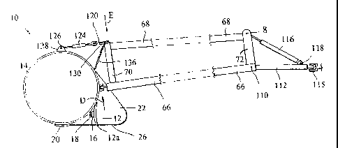
CA 02479911 2011-04-28
7
Referring to Figures 4 and 5, when not being used for levelling, the apparatus
can be
transported by means of a pair of road wheels 32. These are carried one on
each of two
legs 34 that are welded to a cross bar 36 to make up a fork 38. The cross bar
straddles
the beam so that the wheels are located one on either side of the beam. The
cross bar
pivots on an axle 40 mounted on trunnions 42 welded to the beam and the fork
is able to
pivot between a transport position, shown in Figure 4 at 46 and a retracted
position
shown in Figure 5 at 44. The mechanism that causes the fork to pivot is
described
below.
The apparatus also includes a foldable, triangulated drawbar assembly 50. For
convenience the position of the drawbar shown in Figure 2 will be called the
`unfolded'
position and the position shown in Figure 3 will be called the `folded'
position. The
drawbar assembly comprises a pair of fabricated steel bars 52, 54 that come
together at
56 adjacent the forward end of the drawbar assembly 50 where they are
pivotably joined
together by means of a pin 58. At their rear ends 60 the bars are spaced apart
and are
pivotably joined to the beam 14 by means of pins 62, 64 located one on each
side of the
longitudinal centre of the beam 14 and at equal distances therefrom. The axis
of the pin
58 is parallel to the axes of the pins 62, 64.
The pins 62, 64 are disposed with their axes approximately vertical to the
ground. The
bar 52 is of fixed length and is comprised essentially of two steel pipes 66,
68 located
one above the other and joined together by spaced members of which only two
70, 72
are visible in the drawing and are discussed in greater detail below.
The bar 54 also comprises two steel pipes 74, 76. However, in this case, the
pipe 74
slides telescopically into the pipe 76. The pipe 76 pivots about the pin 58.
The lengths
of the pipes 74, 76, and the arrangement of the pins 62, 64, 58 is such that
the bar 52 is
able to pivot about the pin 62 from the position shown in Figure 2 to the
position shown
in Figure 3. In this movement, the pipe 74 slides out of the pipe 76,
effectively
increasing the length of the bar 54. In the unfolded position the two pipes
74, 76, one
inside the other, make the bar 54 substantially rigid. In the unfolded
position the beam
14 is disposed athwart the direction of motion of the drawbar assembly when
the
apparatus is being drawn forward by a tractor in a ground levelling operation.
In the
folded position the beam is disposed substantially in line with the direction
of motion
CA 02479911 2011-04-28
8
of the drawbar assembly when the apparatus is being moved by a tractor or
other prime
mover, for example from one work place to another.
A first latch arrangement 80 (located adjacent the intersection between the
pipe 74 and
the beam 14 and shown in Figure 7) is provided to lock the two pipes 74, 76
together
when the drawbar assembly is in the unfolded position. This latch arrangement
comprises a latch member 82 that pivots about a pin 84 mounted between a pair
of
trunnions 86. The trunnions are welded to the pipe 76 close to the rear end
thereof. The
latch member 82 has a hook formation 88. A catch member 90 is welded to the
pipe 74
close to the rear end thereof and in line with the latch member. As the pipe
76 moves to
the unfolded position, the latch member rides over the catch member and drops
under its
own weight into the position shown in Figure 7 with the hook formation
engaging the
catch member. The latch member can be lifted out of engagement with the catch
member by a drawstring 92 led to the cab of the prime mover, as will be
described.
A second latch arrangement 94 is mounted on the bar 52 and engages the end of
the
beam 14 to lock the two bars 52, 54 to each other and to the end of the beam
when the
drawbar assembly 50 is in the folded position shown in Figure 3. As shown in
Figure 6,
the second latch arrangement 94 comprises a latch member 96 that pivots about
a pin 98
mounted on a trunnion 100 welded to the lower pipe 66 of the bar 52. A hook
formation
102 is formed in the latch member 96. The location of the trunnion is chosen
so that,
when the bar 52 moves to the folded position, the trunnion carries the latch
member 96
across the outer face 104 of the end plate 24 of the beam. In this movement
the pipes
66, 68 move into the respective recesses 28, 30 of the end plate 24 and the
latch member
96 rides over a catch member 106 welded to the outer face and drops under its
own
weight into a position in which the hook formation 102 engages the catch
member 106.
This second latch arrangement 94 locks the pipes 66, 68 in the recesses of the
end plate
24. The bars 52, 54 and the beam are also thus locked together against
vertical
movement, allowing the drawbar assembly to lift the end 14a of the beam for
transport
as will be described. The latch member 92 can be lifted out of engagement with
the
catch member 106 by a drawstring 108 led to the cab of the prime mover.
CA 02479911 2011-04-28
9
When the drawbar assembly 50 is in the unfolded position, without leaving his
seat, the
driver pulls the drawstring 92 to unlock the latch member 82. The driver can
then
manoeuvre the tractor in a roughly circular path, to move the drawbar assembly
50 to
the folded position. In this movement, the end 14a of the beam sits firmly on
the ground
and the bar 52 pivots about the pin 62. The bar 54 pivots about the pin 64,
extending in
length telescopically in the process. When the drawbar assembly arrives at the
folded
position, the latch member 92 automatically locks the two bars 52, 54 against
the beam
14.
The driver can also, again without leaving his seat on the tractor and by
pulling the
drawstring 108, unhook the latch member 96 and thereby release the drawbar
assembly
from its folded position. Using the tractor, the driver can then, again
driving in a
roughly circular path, move the drawbar assembly back to the unfolded position
in
which it is automatically locked by the latch member 82.
As shown in Figures 2 and 3, a conventional hitch bar is mounted at the
forward end of
the drawbar assembly 50 for connecting the apparatus to the two lower links
(plough
arms) of the three point hitch (not shown) of a tractor. The forward end of
the drawbar
assembly can thus be raised or lowered simply by raising or lowering the
plough arms.
For tractors that do not have plough arms, the modification shown in Figure 1
may be
used. Here, the forward end of the bar 52 is connected through a pivot pin 110
to a rigid
fore-and-aft extending towbar 112. The forward end of the towbar is provided
with a
conventional eye by means of which it can be hitched to the drawbar 115 of a
tractor. A
hydraulic ram 116 is connected at one end to the towbar 112 through a pin 118
and at its
opposite end to the upper end of the upright 72 of the drawbar assembly
through a pin
120. By this means the towbar 112 is held in a fixed position relative to the
drawbar
assembly 50 which can be raised or lowered by actuation of the ram 116.
As already described, the bar 52 in the present example is comprised of a
vertically
disposed frame made up of the pipes 66, 68 and the uprights therebetween
(including
the uprights 70, 72). The bar must be strong enough to withstand the
considerable forces
applied to it in use. The joint between the bar 52 and the beam 14 must be
rigid and at
the same time allow the bar to pivot between the folded and unfolded
positions. To this
end a first plate 120 is welded to the extreme upper end of the upright 70.
The plate 120
CA 02479911 2011-04-28
is positioned so that a predrilled hole 122 therein is in alignment with the
axis of the pin
62. One end of a bottle screw 124 is anchored in the hole 122. The opposite
end of the
bottle screw is pivoted to a horizontally disposed pin 126 carried by a pair
of trunnions
128 standing up from the beam, being welded thereto at a position directly
behind the
5 upright 70. If the drawbar assembly is assumed to be held in a fixed
position,
adjustment of the length of the bottle screw causes the beam to rotate about
its'own
longitudinal axis relative to the drawbar assembly. Once set and held in
position as will
be described, the bottle screw prevents the beam from further such relative
rotation.
This is important because, for reasons which will be explained, when the
apparatus is
10 being used in a levelling operation, the elevation above the ground of the
knife edge 12a
relative to the skid bar 20 should be controlled solely by raising or lowering
the forward
end of the drawbar assembly 50. This would not be possible if the beam was
able to
rotate freely relative to the drawbar assembly.
If the levelling apparatus is to be used on a tractor without plough arms, the
bottle screw
124 can be replaced by a ram that is connected to the hydraulic system of the
tractor and
is controllable by the driver. The hitch bar 114 is omitted and the towbar 112
is
connected to the towing hitch of the tractor. Operation of the ram causes the
forward
end of the drawbar assembly 50 to be raised or lowered.
A second plate 130, provided with two holes 132, 134 is welded to the upright
70 at a
short distance below the plate 120. The upper ends of two link chains are
connected to
the respective holes 132, 134. For clarity the chains are shown only as lines
136, 138.
The lower ends of the chains are connected to the beam, one on either side of
the
upright 70. As shown in Figure 10, the hole 132 is positioned so that, as the
bar 52
moves from the folded position to the unfolded position, the hole 132 moves
from the
left to the right of the axis of the pin 62. The hole 134 is located to the
right of the axis
of the pin 62 and is positioned so that it moves further away from the beam as
the bar 52
moves from the folded position to the unfolded position. This positioning of
the holes
132, 134 has the result that, when the drawbar assembly is in the unfolded
position the
chains can be set up taut; however, they become slack when the drawbar
assembly
moves to the folded position. In the unfolded position, the chains and the
bottle screw
124 serve to brace the upright 70 and help reduce twisting of the beam about a
line
extending in the direction of motion of the apparatus. Excessive twisting
CA 02479911 2011-04-28
11
of this kind would cause the beam to rotate about its longitudinal axis,
through the
action of the bottle screw. This is undesirable for reasons already mentioned.
The
bottle screw alone would be unable to prevent such twisting.
When the apparatus is to be used, the wheels are locked in the retracted
position and
the drawbar assembly is locked in the unfolded position by the latch
arrangement 80.
The forward end of the drawbar assembly is hitched to the plough arms of the
tractor
and thus supported above the ground. The mechanism for moving the wheels
between
the retracted position and the transport position includes a bar 140. One end
140a of
the bar 140 is pivotably connected to the bottom of the pipe 66 at a short
distance from
the pin 62. The opposite end 140b of the bar 140 is pivotably connected to a
lever 142
welded to the cross bar 54 of the fork that carries the wheels. When the
drawbar
assembly is moved to the unfolded position, the bar 52, acting through the bar
140,
causes the fork to rotate to move the wheels to the retracted position. When
the
drawbar assembly is moved to the folded position, the opposite happens; i.e.
the bar
52, again acting through the bar 140, causes the fork to rotate to move the
wheels to
the transport position.
When the wheels 32 are in the transport position, the drawbar assembly 50 is
in the
folded position, nestled against and locked to the beam by the latch
arrangement 94.
The beam is lifted off the ground, supported by the wheels and the drawbar
assembly
hitched to the tractor. In this configuration, the tractor can tow the
apparatus to a new
work place. The beam is disposed with its axis in line with the direction of
motion of
the tractor. This is very convenient for towing the apparatus. If either the
beam or the
drawbar assembly was disposed athwart the direction of motion of the tractor
during
transport, the apparatus would not be allowed on public roads without special
permission.
The bar 52 is cranked as shown at 150 to ensure that the apparafus is
correctly lined up
behind the tractor in use and also behind the towing vehicle when it is being
transported.
In a levelling operation, the height of the forward end of the drawbar
assembly is
adjusted (by lowering or raising the plough arms of the three point hitch),
causing the
CA 02479911 2004-09-20
WO 03/080943 PCT/AU03/00374
12
beam to rotate about its longitudinal axis until the skid bar 20 and the knife
edge 12a
of the cutting edge 12 are level with each other. This is what may be
described as the
"normal" working position of the knife edge relative to the skid bar and to
the level of
the ground. The applicant has found that levelling with this as well as with
conventional levelling apparatus, levelling is optimal when a bank of earth of
chosen
height, typically about 10 cm, is maintained just ahead of the cutting edge.
The height
of this bank may vary depending on the condition of the soil. The operator
must
control the apparatus to maintain the bank at the chosen height. If the
operator sees that
the height of the bank is increasing, he must cause the elevation of the knife
edge
(relative to the ground) to be raised. This allows more soil to escape under
the knife
edge and causes the height of the bank to diminish slowly. If the height of
the bank
decreases below the chosen height, the operator must cause the elevation of
the knife
edge to be lowered to allow less soil to escape under the knife edge.
In the present apparatus the elevation of the knife edge is controlled simply
by raising
or lowering the plough arms of the tractor and hence the drawbar assembly 50
at the
hitch 114. In the present example the length of the drawbar assembly from the
hitch
bar to the pins 62, 64 is about 7 in. A substantial advantage of the present
invention is
that this length is much greater than the distance between the skid pad 20 and
the knife
edge 12a (equal in the present example to about 225 mm). The ratio of these
distances
is about 30:1. Thus, if the three point hitch raises the hitch 114 by 30 mm,
the
elevation of the knife edge, relative to the skid pad 20, is raised by only 1
mm. A
differential of 30: 1 in changes of the respective elevations enables the
levelling
operation to be very finely controlled.
It may be advantageous to provide the levelling apparatus with pairs of
auxiliary
wheels, shown schematically at 160, located behind and adjacent each end of
the beam
14. Each pair of wheels may be carried on axles 162 mounted on arms 164. The
arms
are pivotably mounted at their inner ends on trunnions 166 welded to the beam
14. The
outer ends of the arms are connected to the beam by bottle screws 168. These
are used
to adjust the position of the arms so that, in a normal levelling operation,
the bottom
points 170 of the wheels are level with the skid bar and the knife edge 12a,
i.e. just
touching the ground. If the front end of the drawbar assembly is now lifted,
the beam
14 is lifted off the ground. This is useful for at least two reasons. It
enables the cutting
CA 02479911 2004-09-20
WO 03/080943 PCT/AU03/00374
13
edge to be lifted over any earth piled in front of the cutting edge at the end
of a pass. It
also enables the apparatus to be moved quickly from one place to another in a
work
area. However, it is not intended that the wheels should be used to support
the beam
above the ground in a normal levelling operation. It is important that the
beam should
be in contact with the ground over substantially the entire length of the skid
bar. This
much reduces any tendency of the beam to sway up or down at its ends, to dig
into the
ground along its entire length or to bounce up and down. These advantages
would be
lost if the beam was supported above the ground by the wheels.
In the present example, the ratio of the length of the drawbar assembly to the
distance
between the knife edge 12a and the point 170 is about 10:1. The applicant has
operated
the apparatus described herein experimentally with the beam lifted off the
ground by
the wheels 160 and has found that, apart from the disadvantages mentioned
above, the
fine control of the position of the cutting edge is clearly diminished.
Although the
judgement is subjective, based on this experience, the applicant considers
that the ratio
of the length of the drawbar assembly to the distance between the skid bar 20
and the
knife edge 12a should not be less than about 15:1 and certainly not less than
12:1.
It is not essential that the road wheels 32 be attached to the beam. If they
are omitted,
the apparatus can be supported on a separate dolly for transport.