Note: Descriptions are shown in the official language in which they were submitted.
CA 02480040 2004-08-27
ENCLOSURE-COLLATtNG DEVICE, IN PARTICULAR
FOR MAIL-PROCESSING INSTALLATIONS
Background
[001] The invention pertains to an enclosure-collating device, in particular
for
mail-processing installations, having an enclosure-forwarding device, which
exhibits
endless, driven, circulating conveying chains or conveying belts that are
provided
with conveying fingers that project beyond the surface of a collating path in
the
region of the top chain or belt strands and, in pairs, define enclosure-
conveying
compartments located in front of them as seen in the conveying direction. In
the
case of known enclosure-collating devices, enclosure-feeding devices are
located
alongside the collating path over the course of said collating path, and serve
for
introducing individual documents into the enclosure-conveying compartments
that
are being conveyed past.
[002] This known design of enclosure-collating devices provides that the
enclosure-conveying arrangement is driven intermittently in such a way that
conveying-finger pairs that define an enclosure-conveying compartment located
in
front of them are stopped immediately before the introduction region of an
enclosure-
feeding device and then the enclosure-feeding device is started in order to
insert or
dispense an enclosure into an enclosure-conveying compartment perpendicularly
to
the conveying direction of the enclosure-conveying arrangement.
[003] If one wants to drive the enclosure-conveying arrangement continuously
in
order to increase the operating speed of the enclosure-collating devices,
then, in
combination with such a continuously driven enclosure-conveying device,
special
forms of enclosure-feeding devices are required that discharge or insert
enclosures
into the enc{osure-conveying compartments from above.
[004] If conventional enclosure-feeding devices of the type briefly described
above, which feed enclosures into the conveying compartments from the side and
perpendicular to the conveying direction of the enclosure-conveying
arrangement,
are to be used in combination with continuously driven enclosure-conveying
1
CA 02480040 2004-08-27
arrangements, then these conveying compartments must be dimensioned very large
in the conveying direction of the enclosure-conveying arrangement, which
requires a
large spacing of the enclosure-conveying compartments along the enclosure-
conveying direction, and the advantage.of a continuous driving of the
enclosure-
conveying arrangement in the sense of an increase in operating speed is
largely
negated. This is due to the fact that in addition to the format of the
enclosure to be
inserted, an enclosure-conveying compartment that is to be filled during its
continuous movement must be made larger by at least one segment, in the
conveying direction of the enclosure-conveying arrangement, which corresponds
to
the time of the complete insertion of an enclosure by the enclosure-feeding
device
transversely to the conveying direction of the enclosure-conveying
arrangement,
multiplied by the conveying speed of the enclosure-conveying arrangement.
Summary of the Invention
[005] Accordingly, the invention is to solve the problem of developing an
enclosure-collating device of the type described briefly at the beginning in
such a
way that a high operating speed of the enclosure-conveying arrangement is
attained,
in particular, when being driven continuously. The problem on which the
invention is
based also inciudes reducing the spacing of the enclosure-conveying
compartments
in the conveying direction and increasing the cycle speed of the enclosure-
feeding
devices located on the course of the collating path, and of additional
processing
stations, for example, in a mail-processing installation.
[006] The invention also pertains to enclosure-collating devices with
intermittent
drive of the enclosure-conveying arrangement, since through implementation of
the
inventive design, the possibility is provided of, for example, having a
specific
insertion compartment in front of the conveying finger pair that defines it
restarted
early after it has been stopped at the start of the introduction region of an
enclosure-
feeding device, after, as a result of the action of the oblique conveying
device, the
trailing edge of an enclosure specified for the relevant enclosure-conveying
compartment leads the conveying fingers that later grasp this edge. Thus, even
during cyclical operation of the enclosure-conveying arrangement, a shortening
of
2
CA 02480040 2006-09-25
the cycle times is achieved, which is also accompanied by less abrupt
deceleration
and acceleration of the controlled parts as well.
In accordance with an aspect of the present invention, there is provided an
enclosure-collating device, in particular for mail-processing installations,
having:
an enclosure-conveying arrangement having driven conveying fingers forming
enclosure-conveying compartments on a collating path; and
at least one enclosure-feeding device located alongside the collating path and
containing a transfer device for introducing individual documents into the
enclosure-
conveying compartments;
wherein the transfer device contains an intermediate conveying device by
means of which individual enclosures from a supply of enclosures or a stream
of
separate enclosures are conveyed in the direction of the enclosure-conveying
arrangement to a conveying end position;
wherein the conveying end position of the intermediate conveying device
is followed by an oblique conveying device which grips enclosures located in
the
conveying end position of the intermediate conveying device and conveys them
with transiatory movement, at an angle (90 -a) to the conveying directions of
the
intermediate conveying device into an enclosure-conveying compartment of the
enclosure-conveying arrangement;
wherein a control unit controls a drive of the oblique conveying device in
dependence on the drive speed of the drive or the enclosure-conveying
arrangement such that a vector of the speed of an enclosure on account of
being
driven by the oblique conveying device has a component in the direction of the
collating path which is essentially equal to a vector of the drive speed of
the
conveying fingers;
wherein the intermediate conveying device is driven continuously;
wherein the intermediate conveying device conveys the enclosures
against nips of intermittently driven pairs of rollers of the oblique
conveying
device, said roller nips, while at a standstill, serving as a stop and
wherein the enclosure-conveying arrangement is driven intermittently, and the
oblique conveying device is switched on intermittently.
In accordance with another aspect of the present invention, there is provided
an enclosure-collating device, in particular for mail-processing
installations, having:
3
CA 02480040 2006-09-25
an enclosure-conveying arrangement having driven conveying fingers
forming enclosure-conveying compartments on a collating path; and
at least one enclosure-feeding device located alongside the collating path
and containing a transfer device for introducing individual documents into the
enclosure-conveying compartments;
wherein the transfer device contains an intermediate conveying device by
means of which individual enclosures from a supply of enclosures or a stream
of
separate enclosures are conveyed in the direction of the enclosure-conveying
arrangement to a conveying end position;
wherein the conveying end position of the intermediate conveying device is
followed by an oblique conveying device which grips enclosures located in the
conveying end position of the intermediate conveying device and conveys them
with translatory movement, at an angle (90 -a) to the conveying directions of
the
intermediate conveying device into an enclosure-conveying compartment of the
enclosure-conveying arrangement;
wherein a control unit controls a drive of the oblique conveying device in
dependence on the drive speed of the drive or the enclosure-conveying
arrangement
such that a vector of the speed of an enclosure on account of being driven by
the
oblique conveying device has a component in the direction of the collating
path
which is essentially equal to a vector of the drive speed of the conveying
fingers;
wherein the oblique conveying device contains circulating perforated
vacuum-type conveying belts which are guided over vacuum chambers and run in
the conveying direction of the oblique conveying device,
wherein the enclosure-conveying in arrangement is driven intermittently, and
the oblique conveying device is switched on intermittently.
[007] Embodiments are explained in more detail below with references to the
following drawings.
Description of the Drawings
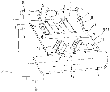
[008] Fig. 1 is a schematic perspective view of an enclosure-collating device
of
the previously described type.
3a
CA 02480040 2006-09-25
[009] Fig. 2 is a schematic perspective representation of an intermediate
conveying device and an oblique conveying device of the transfer device of an
enclosure-collating device according to Fig. 1.
[0010] Fig. 3 is a schematic perspective representation of another embodiment
of
the intermediate conveying device and the oblique conveying device of the
transfer
device for an enclosure-collating device according to Fig. 1.
Detailed Description of the Invention
[0011] Fig. 1 shows in a perspective, highly schematicized representation, a
detail of an enclosure-collating device of the type being suggested here. It
contains
an enclosure-conveying arrangement I with endless, according to the present
embodiment, continuously driven, circulating conveying chains or conveying
belts 2,
3 that are provided with conveying fingers 4, 5. The conveying chains or
conveying
belts are guided by chain wheels or pulleys at the beginning and end of the
enclosure-conveying arrangement, as is shown only schematically in Fig. 1,
whereby
a chain-wheel pair or a pulley pair is coupled with a suitable driving means.
In the
region of the top strands of the conveying chains or conveying belts 2, 3, the
conveying fingers 4, 5 project above the surface 6 of a collating path 7 and,
in pairs,
define enclosure-conveying compartments 8 and 9 that are located in front of
them
as seen in the conveying direction. Enclosure-conveying segments or
compartments
3b
CA 02480040 2004-08-27
of the functional type of the compartments 8 and 9 can also be defined without
the
use of conveying fingers.
[0012] Located alongside the collating path 7 are enclosure-feeding devices
10,
11, which contain transfer devices 12 for feeding individual enclosures into
the
enclosure-conveying compartments 8 and 9. In turn, each of the transfer
devices 12
contains an intermediate conveying device 13 by means of which individual
enclosures from a supply of enclosures or from a stream of separate enclosures
are
conveyed in the direction of the enclosure-conveying arrangement essentially
perpendicularly to the conveying direction of the latter. The intermediate
conveying
devices 13 are in the form of endless conveyor belts or conveying belts 15,
which
are put into circulation by driving means 14 and the top strands of which
project
through cutouts slightly above the surface of transfer tables 16 and which
have the
task of frictionally connecting these top strands from underneath to
enclosures that
have been applied through a means (not shown) and moving such enclosures
forward in the direction perpendicular to the conveying direction of the
enclosure-
conveying arrangement.
[0013] It is significant that the frictional forces between the enclosures
laid on the
transfer tables 16 on the one hand and the top strands of the conveying belts
or
conveyor belts 15 on the other are dimensioned in such a way that next, after
placing
an enclosure from a supply of enclosures or from a stream of separate
enclosures
onto the transfer table 16, a reliable conveying perpendicular to the
conveying
direction of the enclosure-conveying arrangement takes place, but then, when
an
enclosure has been completely conveyed onto the transfer table 16 and is lying
on
same, a further conveying of the relevant enclosure with a movement component
transverse to the conveying direction of the intermediate conveying device 13,
i.e.,
transverse to the running direction of the conveyor belts or conveying belts
15, is
possible.
[0014] To adjust the frictional forces between the undersides of enclosures
forwarded by the enclosure-feeding devices 10 and 11 on the one hand and the
top
sides or outsides of the conveyor belts or conveying belts 15 on the other,
pressing
means that are familiar to the person skilled in the art can be provided in
the region
4
CA 02480040 2004-08-27
of the transfer devices 12, although they are not shown in the drawing. Such
pressing means have, for example, the form of brush strips or of plates
mounted at a
suitable distance above the transfer tables 16, or else of rolling balls held
and
supported in cages or cage arrangements that lie with limited pressing force
on the
fed enclosures.
[0015] Once an enclosure in the enclosure-feeding device 10, 11 has been
completely laid onto or conveyed forward onto a transfer table 16 by means of
the
intermediate conveying device 13, the relevant enclosure is brought to a
standstill on
its conveying path perpendicular to the conveying direction of the enclosure-
conveying arrangement by a stopping means, not shown in Fig. 1, and is only
released for further conveying when an enclosure-conveying compartment 8, 9
that
is able to receive it moves past the relevant enclosure-feeding device 10, 11.
[0016] Once the traiiing end, as seen in the conveyirig direction of the
enclosure-
conveying arrangement, of an enclosure-conveying compartment 8, 9 is
essentially
flush with the trailing edge, relative to the mentioned conveying direction,
of an
enclosure lying on the transfer table 16, as is indicated by the dot-dash
lines 17 and
18 in Fig. 1, an oblique conveying device 19 and 20 of the transfer device 10
and 11
grips a particular enclosure lying on the transfer table 16 and conveys this
enclosure
from the conveying end position of the intermediate conveying device 13 in a
translatory, essentiaily linear movement at an angle a to the conveying
direction of
the envelope-conveying device I obliquely into the associated enclosure
compartment 8 and 9, whereby as a result, the trailing edge, as seen in the
conveying direction of the enclosure-conveying arrangement, of the obliquely
conveyed enclosure moves away in front of the rear delimitations 17, 18 of the
enclosure-conveying compartments as a result of the transiatory, oblique
conveying
until the oblique conveying devices 19, 20 have released the particular
enclosure
and a side edge of the relevant enclosure has pushed against a guide flange or
guide straightedge 21 of the collating path 1.
[0017] The oblique conveying of enclosures into the enclosure compartments 8,
9
in an essentially linear movement as described and explained with the aid of
Fig. 1
has the advantage over a translatory circular movement that adjusting the
CA 02480040 2006-09-25
coordinated control of the particular conveying driving means and the
adjusting of
the conveying phases to the formats of the enclosures to be inserted and to
the
particular drive speeds are simple and concise.
[0018] It should also be mentioned with reference to Fig. 1, that the oblique
conveying devices 19, 20 perform an oblique conveying of the enclosures
delivered
by the intermediate conveying devices 13 linearly at a speed such that after
the
obliquely conveyed enclosures come free of the oblique conveying devices 19,
20,
the enclosures are moved ahead up to the stop flange or the stop straightedge
21
while finally completely filling the enclosure-conveying compartments 8 and 9,
so
that in the embodiment shown in Fig. 1, the oblique conveying devices 19, 20
are
always located completely outside the conveying route of the enclosures along
the
enclosure-conveying arrangement 1.
[0019] However, if all that is involved in the case of the oblique conveying
devices
19, 20 is a system that grips the top of an enclosure that is to be inserted
into an
enclosure-conveying compartment 8, 9, then it is not necessary for the oblique
conveying devices 19, 20 to be located completely outside the path of the
enclosures
on the enclosure-conveying device 1. For example, the oblique conveying
devices
19, 20 can then involve obliquely conveying friction roller sets that act only
above the
enclosure surfaces, or circulating belts that are provided with vacuum
openings and
do not require a support mechanism below the level of the transfer tables 16
or the
collating path of the enclosure-conveying arrangement.
[0020] For implementation of the movement sequences previously described in
connection with Fig. 1 in the region of the intermediate conveying devices 13
and the
oblique conveying devices 19, 20, as well as in the region of the enclosure-
conveying arrangement 1, a control unit is provided which is not shown in Fig.
1, but
which controls a driving means of the oblique conveying devices 19, 20 in
dependence on the drive speed of a driving means of the enclosure-conveying
arrangement 1 in such a way that the vector of the speed of an enclosure as a
result
of being driven by the oblique conveying devices 19, 20 has a component in the
direction of the collating path that is essentially equal to the vector of the
drive speed
of the conveying fingers 4, 5. For example, if the magnitude of the drive
speed of the
6
CA 02480040 2004-08-27
conveying fingers 4, 5 is equal to V, then the magnitude of the drive speed of
the
oblique conveying devices 19, 20 is V/cos a, as is made clear in Fig. 1 by the
corresponding arrows.
[0021] The thoughts that were discussed above show the usefulness of an
oblique feeding of enclosures into the enclosure-conveying compartments 8, 9
during continuous driving of the conveying fingers 4, 5, whereby the
individual
enclosure-conveying compartments 8, 9 can have less spacing in the conveying
direction of the enclosure-conveying arrangement 1 than the corresponding
known
devices do. However, as has already been indicated earlier, oblique feeding of
enclosures by the transfer devices 10, 11 is advantageous even with
intermittent
driving of the conveying fingers of the collating path, since with oblique
feeding of
enclosures the feeding phase can overlap chronologically with the movement
phases
of the conveying fingers 4, 5, as a result of which the operating procedure is
accelerated and in turn the dimension of the enclosure-conveying compartments
in
the conveying direction can be reduced.
[0022] In addition, when compared with a feeding of enclosures into the
conveying compartments from above, the feeding of enclosures into the
enclosure-
conveying compartments 8, 9 during their continuous movement past the transfer
devices 10, 11 has the significant advantage of good accessibility to the
collating
path to clear malfunctions.
[0023] Fig. 2 shows in schematic and perspective representation an embodiment
of an intermediate conveying device and an oblique conveying device for a
transfer
device 10, 11. Parts corresponding to those of the erribodiment according to
Fig. 1
have been provided with the same reference symbols in Fig. 2.
[0024] In turn, the intermediate conveying device 13 has the form of conveyor
belts or conveying belts 15 which are guided parallel to one another, with the
top
strands reaching above cutouts in a transfer table 16, and which are put into
circulation by a driving means 14 and which convey by means of frictional
forces
enclosures from, for example, a supply of enclosures or from a stream of
separate
enclosures that are placed on the transfer table 16, in the direction towards
a
7
CA 02480040 2004-08-27
stopping straightedge 23. Once the leading edge, as seen in the conveying
direction
of the intermediate conveying device 13, reaches the stopping straightedge 23,
the
relevant enclosure is then stopped, whereby, however, the conveyor belts or
conveying belts 15 of the intermediate conveying device 13 remain in
circulation and
run frictionally underneath the stopped enclosure.
[0025] If the stopping straightedge 23 is now pivoted upward on connecting
rods
25 by a driving means 24, the conveyor belts or conveying belts 15,
frictionally on
the underside of an enclosure lying on the transfer table 16, grip said
enclosure and
continue to move it so that the leading edge, as seen in the conveying
direction of
the intermediate conveying device 13, of the enclosure is grasped by two
perforated
belts 26 and 27, which are put into circulation synchronously and are directed
above
vacuum chambers, and which now draw in the enclosure that is aligned in the
conveying direction in accordance with the direction of arrow P1, grasp it,
and
convey it obliquely in a transiatory movement in the direction of arrow P2,
without the
friction between the underside of the enclosure and the conveying belts or
conveyor
belts 15 changing the alignment of the relevant enclosure, since for this
purpose, the
frictional forces between the enclosure and the conveyor belts 15 is
inadequate
versus the strong clamping of the underside of the enclosure by the
circulating
vacuum conveyor belts 26, 27.
[0026] A driving means for the vacuum conveyor belts 26, 27, which is
designated 28, the driving means 14 that moves the conveyor belts or conveying
belts 15, and the driving means 24 for pivoting the stopping straightedge 23
up and
down, are connected to a control unit 29, which also receives detector signals
from
the collating path 7, which is indicated by the dot-dash line at 30, whereby
the
detector signals report the particular operating positions of the conveying
fingers 4, 5
to the control unit 29. With continuously circulating conveyor belts or
conveying belts
15 and continuously circulating vacuum conveyor belts 26, 27 in dependence on
the
particular setting of the conveying fingers 4, 5 of the coilating path 7; this
causes at
the appropriate time a feeding by the oblique conveying device 19, 20 of an
enclosure held ready on the transfer table 16 into an enclosure compartment
for
further conveying of the enclosure in the direction of arrow P3.
8
CA 02480040 2004-08-27
[0027] In a modification of the embodiment just outlined above, the conveyor
belts or conveying belts 15 and the vacuum conveyor belts 26, 27 can also be
driven
intermittently in a suitable chronological overlapping and matched to a work
cycle of
the stopping straightedge 23.
[0028] The embodiment of the transfer device 12 according to Fig. 3 differs
from
the one according to Fig. 2 primarily in that here the use of a stopping
straightedge
23 to stop an enclosure in the region of the intermediate conveying device for
further
conveying by the oblique conveying device 19, 20 is dispensed with.
[0029] In this embodiment, the oblique conveying devices 19, 20 have the form
of
roller pairs 32 and 33 plus 34 and 35, whereby each of the lower rollers 33
and 35 is
placed under the transfer table 16 and projects above the level of the
transfer table
through cutouts in the transfer table in the flat regions at the end of the
conveyor
belts or conveying belts 15 of the intermediate conveying device. The lower
rollers
33 and 35 are driven synchronously intermittently by a driving means 28. The
spring-loaded upper rollers 32 and 34, which are prestressed against the lower
rollers 33 and 35 by prestressing means, not shown, are track rollers. All of
the
rollers 32 to 35 possess drive shafts or bearing spindles having an
orientation
relative to the drive shafts or bearing spindles of the rollers for the
conveyor belts or
conveying belts 15 is (900 + a), so that the conveying direction according to
arrow P2
in turn takes on an angle a with respect to the conveying direction of the
collating
path according to arrow P3.
[0030] During operation, enclosures from a supply of enclosures or from a
stream
of separate enclosures are placed on the transfer table 16 and are conveyed by
the
intermediate conveying device's conveyor belts or conveying belts 15, which
are kept
in continuous circulation while maintaining friction tightness, which allows
movement
of an enclosure with a movement component transverse to the conveying
direction of
the intermediate conveying device according to arrow P1, against the roller
pairs 32
and 33 plus 34 and 35, which at first are still not driven and are standing
still, and
which form with the conveying nip between them a stop for the enclosures
conveyed
by the conveyor belts or conveying belts 15, by means of which the leading
edge, as
seen from the conveying direction according to arrow P1, of an enclosure is
aligned
9
CA 02480040 2004-08-27
parallel to the conveying direction according to arrow P3 of the collating
path, or
remains aligned if an aligned conveying has already taken place.
[0031] If the driving means 28 for the roller pairs 32 and 33 plus 34 and 35
is now
put into operation, then the leading edge, as seen from the conveying
direction
according to arrow P1, of an enclosure is grasped by the conveying nip between
roller pairs 32 and 33 plus 34 and 35 and the enclosure is fed in a
translatory
movement essentially linearly obliquely in the direction of arrow P2 into an
enclosure
compartment of the collating path 7, whereby the same operations take place
relative to the position or the movement of the conveying finger pairs 4, 5 of
the
collating path, as they were discussed previously with reference to Fig. 1.
[0032] Provided in the embodiment according to Fig. 3 as well is a control
unit 29,
by means of which the switching on and switching off of the driving means 28
is
controlled, for example, in dependence on position report signals from the
line 30 in
accordance with the particular instantaneous position of the enclosure-
conveying
compartments. An intermittent switching on of the driving means 14 for the
conveyor
belts or conveying belts 15 of the intermediate conveying device can also be
carried
out by the control unit 29 in accordance with a modified operational mode.
[0033] It should also be noted that in accordance with an embodiment of the
transfer device that is not shown, the intermediate conveying device can also
be
equipped with vacuum conveyor belts similar to the conveyor belts 26 and 27 of
the
embodiment according to Fig. 2 instead of the conveyor belts or conveying
belts 15
that grasp the enclosure undersides frictionally. In this case, through
suitable
adjustment of the vacuum at least in the region of the end of these vacuum
conveyor
belts, care is taken that the oblique conveying device can accept enclosures
from the
intermediate conveying device and with a movement component transverse to the
conveying direction of the intermediate conveying device, can remove them from
same in a translatory, essentially linear movement.