Note: Descriptions are shown in the official language in which they were submitted.
CA 02480140 2010-04-26
DISC CHECK VALVE
Field of the Invention
This invention relates to check valves. More particularly, this
invention relates to check valves for fluids employing a free-floating disc
that allows fluid flow in an unchecked direction with a minimal increase in
fluid pressure and turbulence while maximizing the rate of fluid flow
through the valve.
Description of the Background Art
Presently, there exist many types of disc valves that employ a free-
floating disc that seats in a checked direction of fluid flow and unseats in
an unchecked direction. Optimal designs of disc valves seek to minimize
the increase in fluid pressure in the unchecked fluid flow direction,
minimize turbulence within the valve and maximize the rate of fluid flow
through the valve. It is an object of this invention to provide an
improvement that is a significant contribution to the advancement of the
disc valve art.
Another object of this invention is to provide a disc valve having a
maximum fluid flow rate.
1
CA 02480140 2004-09-22
WO 2003/083335 PCT/US2003/007394
Another object of this invention is to provide a disc valve having a
minimal dimensional package size.
Another object of this invention is to provide a disc valve having a
minimal tendency of the seal disc to stick in the open or closed position.
Another object of this invention is to provide a disc valve having a
minimal seal disc deformation under differential pressure loads.
Another object of this invention is to provide a disc valve having
minimal fluid turbulence through the valve.
Another object of this invention is to provide a disc valve having
high differential seal pressures.
Another object of this invention is to provide a disc valve having a
high ultimate burst pressure.
Another object of this invention is to provide a disc valve having an
improved kinematic action of the seal disc.
Another object of this invention is to provide a disc valve composed
of modular components to enable various assemblies of end connections.
Another object of this invention is to provide a disc valve having an
improved ergonomic design of the valve body/housing.
Another object of this invention is to provide a disc valve having a
simplicity of components.
Another object of this invention is to provide a disc valve capable of
being consistently and durably manufactured/molded and assembled at a
low manufactured cost.
-2-
CA 02480140 2010-04-26
According to one aspect of the present invention there is provided a valve for
controlling the flow of a fluid through a fluid passage such that a fluid flow
in the
fluid passage is permitted in a first direction and restricted in a second
direction, the
valve comprising: a valve body having an internal fluid chamber with internal
side
walls; a valve member contained in the internal fluid chamber, the valve
member
comprising a disc-shaped check valve having a first diameter, the disc-shaped
check
valve comprising a first side and a second side, the first side including a
truncated
torroidal shaped portion having a second outer diameter and a first length,
the second
outer diameter being appreciably less than the first diameter; and an array of
finger-
shaped projections having a base portion connected to the valve body and a
finger-tip
portion for centering the valve member when fluid is flowing through the valve
in the
first direction and when restricted in the second direction, the finger-shaped
projections including a second length appreciably greater than the first
length such
that when the truncated torroidal shaped portion moves in the first direction
the
finger-shaped projections receive the truncated torroidal shaped portion of
the disc-
shaped check valve and fluid is allowed to flow between the finger-shaped
projections
and then over the truncated torroidal shaped portion.
According to a further aspect of the present invention there is provided a
valve
for preventing fluid from flowing in one direction through a fluid channel,
the valve
comprising: a free-floating valve member having a sealing side portion and a
flow
side portion wherein the sealing side portion is substantially flat and the
flow side
portion is substantially cup-shaped, the valve member having a first diameter,
the cup-
shaped flow side portion having a second outer diameter and a first length,
the second
outer diameter being appreciably less than the first diameter; and a valve
body for
containing the valve member wherein the valve body has a valve member
receiving
section having a second length appreciably greater than the first length of
the cup-
shaped portion that is configured, when fluid flow is in an opposite
direction, to
receive and center the cup-shaped portion of the flow side portion of the
valve
member when fluid is flowing through the valve such that fluid flows over the
cup-
shaped portion through openings in the valve member receiving section and,
when
2a
CA 02480140 2010-04-26
fluid is prevented from flowing in the one direction, to center the cup-shaped
portion
of the flow side portion of the valve member.
According to another aspect of the present invention there is provided a
method of preventing fluid from flowing through a pipe in one direction, the
method
comprising: positioning a valve body in the pipe; enclosing a free floating
valve
member having a first diameter inside of the valve body, one side of the valve
member further including a protruding portion having a second outer diameter
and a
first length, the second outer diameter being appreciably less than the first
diameter;
centering the valve member with a flow-through seal member having finger-like
projections by a finger-tip portion thereof having a second length appreciably
greater
than the first length of the protruding portion such that when fluid is
flowing through
the pipe in a flow allowed direction the protruding portion is centered and
received
within the finger-tip portion and fluid is allowed to flow through the finger-
like
projections and then over the protruding portion and when fluid is prevented
from
flowing through the pipe, the protruding portion is centered by the finger-tip
portion.
2b
CA 02480140 2004-09-22
WO 2003/083335 PCT/US2003/007394
Another object of this invention is to provide a disc valve that is
particularly suited for liquid applications, but that may be employed in
limited gas media applications.
Another object of this invention is to provide a disc valve that is
particularly suited for human blood and blood products applications.
The foregoing has outlined some of the pertinent objects of the
invention. These objects should be construed to be merely illustrative of
some of the more prominent features and applications of the intended
invention. Many of the beneficial results can be attained by applying the
disclosed invention in a different manner or modifying the invention
within the scope of the disclosure. Accordingly, other objects and a fuller
understanding of the invention may be had by referring to the summary of
the invention and the detailed description of the preferred embodiment in
addition to the scope of the invention defined by the claims taken in
conjunction with the accompanying drawings.
-3-
CA 02480140 2004-09-22
WO 2003/083335 PCT/US2003/007394
SUMMARY OF THE INVENTION
For the purposes of summarizing this invention, the invention
comprises a free-floating disc type check valve that out-performs similar,
competitive valve designs and offers a wide variety of customer desired
end connections not readily offered by competitive disc valve
manufacturers. The valve was designed specifically for liquid
applications, however limited gas media applications are possible with the
design. Utilization of the valve for human blood and blood products
applications is also intended with this design.
One embodiment of the present invention is directed toward a valve
for controlling the flow of a fluid through a fluid passage such that a fluid
flow in the fluid passage is permitted in a first direction and restricted in
a
second direction. The valve includes a valve body having an internal fluid
chamber with internal side walls. A valve member is contained in the
internal fluid chamber. The valve member is a free floating disc-shaped
check valve having a first side with an attached truncated torroidal
shaped portion and a relatively flat second side. An array of finger-
shaped projections are positioned on the valve body that receive the valve
member when fluid is flowing through the valve in the first direction. The
finger-shaped projections are positioned a distance away from the internal
side walls of the valve body such that the disc-shaped check valve is held
in the center portion of the valve body by the finger-shaped projections
thereby facilitating fluid flow around the outside edges of the disc-shaped
-4-
CA 02480140 2004-09-22
WO 2003/083335 PCT/US2003/007394
check valve. In addition, the finger-shaped projections are dimensioned to
receive the truncated torroidal shaped portion of the disc-shaped check
valve such that fluid is allowed to flow between the finger-shaped
projections. The valve body consists of an inlet portion and an outlet
portion that are designed to sealing couple together to form the valve
body. The inlet portion of the valve body has an annular sealing
protrusion such that when a fluid attempts to flow in the second direction
the annular sealing protrusion and the flat portion of the disc-shaped
check valve couple to create a seal against the fluid flow in the second
direction. In a preferred embodiment, the valve member is constructed of
a single piece of elastomeric material, the inlet portion of the valve body is
constructed from a single piece of plastic and the outlet portion of the
valve body that includes the finger-shaped projections is constructed from
a single piece of plastic. Furthermore, the valve body is preferably
constructed from a clear plastic that allows the operation of the valve to be
visually monitored.
The above described valve offers a number of improvements over
the prior art. First, the finger like projections restrict the movement of
the valve member in the valve body and significantly reduce the likelihood
that the valve member will become jammed in the open or closed position.
In addition, the truncated torroidal structure adds rigidity to the valve
member that keeps it from bending or becoming stuck when sealing the
valve in response to a fluid flow in the restricted direction through the
-5-
CA 02480140 2004-09-22
WO 2003/083335 PCT/US2003/007394
valve. Finally, the simplistic construction and operation of the valve
decreases the costs associated with use of the valve. Thus, the above
described embodiment offers a number of improvements in the prior art.
Another embodiment of the present invention is directed toward a
valve for preventing fluid from flowing in one direction through a fluid
channel. The valve includes a valve member having a sealing side portion
and a flow side portion wherein the sealing side portion is substantially
flat and the flow side portion is substantially cup-shaped. A valve body
contains the valve member. The valve member is constructed from a
single piece of elastoineric material coated with a non-stick material that
minimizes friction between the valve member and valve body. The valve
body has a valve member receiving section that is configured to receive the
flow side portion of the valve member when fluid is flowing through the
valve such that fluid flows through openings in the valve member
receiving section. The valve member receiving section includes a plurality
of projections positioned such that an opening exists between each
projection and such that the valve member is centered within the valve
body when received by the valve member receiving section. Preferably,
the plurality of projections are finger-shaped and arranged in an
substantially circular configuration. In such an embodiment, the flow side
portion of the valve member is then received inside of the substantially
circular projection configuration when fluid is flowing through the valve
-6-
CA 02480140 2004-09-22
WO 2003/083335 PCT/US2003/007394
such that the fluid flows around the outside edges of the valve member
and between the plurality of projections.
Yet another embodiment of the present invention is directed toward
a method of preventing fluid from flowing through a pipe in one direction.
The method commences by positioning a valve body in the pipe.
Preferably, the valve body is constructed out of a transparent material
such that proper operation of the valve can be visually confirmed. A free
floating valve member is then enclosed inside of the valve body. The valve
member is configured to create a hydrodynamic sealing force on the valve
member when fluid attempts to flow through the pipe in the flow-inhibited
direction. The valve member is engaged with a flow-through seal member
having finger-like projections such that it is centered in the valve body
when fluid is flowing through the pipe in the flow allowed direction. The
free floating valve member is engaged with a flow-inhibiting seal member
when fluid is attempting to flow through the pipe in the flow-inhibited
direction.
The above described embodiments improve upon the prior art by
using the finger-like projections to center the valve member in the valve
body such that the flow rate is maximized and the failure rate due to the
valve member becoming stuck is minimized. In addition, configuring the
valve member to create a hydrodynamic sealing force helps move the valve
member from the open position to the closed position while insuring that it
does not become stuck. The use of a transparent construction allows a
-7-
CA 02480140 2004-09-22
WO 2003/083335 PCT/US2003/007394
user to visually inspect the valve to determine if it is properly operating.
Thus, the above described method offers a number of advantages over the
prior art.
The foregoing has outlined rather broadly the more pertinent and
important features of the present invention in order that the detailed
description of the invention that follows may be better understood so that
the present contribution to the art can be more fully appreciated.
Additional features of the invention will be described hereinafter which
form the subject of the claims of the invention. It should be greatly
appreciated by those skilled in the art that the conception and the specific
embodiment disclosed may be readily utilized as a basis for modifying or
designing other methods for carrying out the same purposes of the present
invention. It should also be realized by those skilled in the art that such
equivalent methods do not depart from the spirit and scope of the
invention as set forth in the appended claims.
-8-
CA 02480140 2004-09-22
WO 2003/083335 PCT/US2003/007394
BRIEF DESCRIPTION OF THE DRAWINGS
For a more succinct understanding of the nature and objects of the
invention; reference should be directed to the following description taken
in conjunction with the accompanying drawings in which:
Fig. 1 is a cross-sectional view of the assembled disc valve of the
invention;
Fig. 2 is a cross-sectional view of the downward flow portion of the
disc valve of the invention;
Fig. 3 is an end view of Fig. 2;
Fig. 4 is a cross-sectional view of the disc of the disc valve of the
invention;
Fig. 5 is an end view of Fig. 4;
Fig. 6 is a cross-sectional view of the assembled disc valve of the
invention, with male and female luer lock fittings;
Fig. 7 is a cross-sectional view of the assembled disc valve of the
invention with luer fittings;
Fig. 8 is a cross-sectional view of the assembled disc valve of the
invention with male luer lock fittings;
Fig. 9 is a cross-sectional view of the assembled disc valve of the
invention with a female luer lock fittings;
Fig. 10 is a cross-sectional view of the assembled disc valve of the
invention with tube and male luer lock fittings;
-9-
CA 02480140 2004-09-22
WO 2003/083335 PCT/US2003/007394
Fig. 11 and 12 is a cross-sectional view of the assembled disc valve
of the invention with tube and male luer lock fittings; and
Fig. 13 is a diagram showing the flow rates of the disc valve of the
invention as compared to several prior art disc valves.
Similar reference numerals refer to similar parts throughout the
several figures.
-10-
CA 02480140 2004-09-22
WO 2003/083335 PCT/US2003/007394
DETAILED DESCRIPTION OF THE PREFERRED EMBODIMENT
A. Seal Disc Configuration and Function:
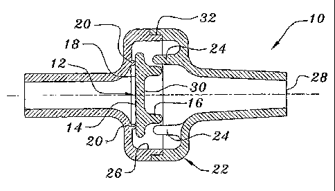
As shown in Figs. 1-5, the new disc check valve utilizes a unique
seal disc 12, employing a specific geometry to accomplish multiple specific
functions in operation. The configuration of the seal disc 12 may be
described as a flat circular disc 14 integrally mated to a modified,
truncated torroidal shape 16 projecting from the downward-flow surface of
the disc 12. The torroidal shape 16 is the key element of the design of the
seal disc 12. This geometry provides the following functional features:
1. The cylindrical mass of the torus 16 on one side of the disc 12
imparts structural rigidity to the seal, helping to keep the seal surface 18
of the disc 12 flat with respect to the annular seal 20 of the valve body 22.
The torus 16 shape is positioned so as to have its mass over the annular
seal 20. Deflection of the valve seal disc 12, and ultimate leakage or
failure, is minimized under higher differential pressures. "Compression
set", or permanent deformation of the valve seal disc 12 is mitigated by the
structural stiffness added by the torroidal shape 16, and flexural
deformation in transition between open and closed positions of the valve
seal 12 are minimized. This helps to prevent "sticking" or locking of the
valve seal 12 in the open or closed position evidenced in traditional check
valves utilizing a common flat disc seal.
2. The torroidal shape 16 is designed to work in conjunction
with "fingers" or projections 24 inside the valve body 22. These projections
- 11 -
CA 02480140 2004-09-22
WO 2003/083335 PCT/US2003/007394
24 loosely surround the periphery of the torus 16 limiting the lateral
displacement of the seal disc 12 in relation to the annular seal 20 of the
valve body 22. The projections 24 are designed to permit predetermined
axial travel of the valve seal disc 12 to the open position permitting fluid
flow through the valve body 22. The specific profile of the periphery of the
torus 16 is also designed to allow angular displacement of the seal disc 12
with respect to the centerline axis of the valve assembly 10, while
preventing the seal disc 12 from becoming wedged or entrapped in the
open position with the "fingers" or projections 24. In this arrangement,
the axial displacement of the seal disc 12 and annular clearance between
the circumference of the valve seal disc 12 and the annular seal 20 of the
valve body 22 is maximized, along with the annular area between the seal
disc 12 and the valve body internal wall 26. The outer profile of the
torroidal shape 16 also functions cooperatively with the internal valve
body shape to direct fluid flow transitionally into the convergent orifice of
the 'valve body outlet 28 when the disc 12 is in the open position, as
discussed further in section "Valve Performance, Flow and Pressure".
3. The "cup" shape formed by the modified torus 16, and
bounded on one axial end by the flat disc shape, forms a piston 30 that
takes advantage of liquid flow moving from the distal toward the proximal
end of the valve interior and uses the hydrodynamic force of the liquid to
assist in moving the seal disc 12 from the open to the closed position. The
velocity of the fluid is higher in proximity to the center axis of the valve
-12-
CA 02480140 2004-09-22
WO 2003/083335 PCT/US2003/007394
assembly 10 as is the fluid pressure, due to the projections 24, or "fingers",
surrounding the annular seal 20 directing the larger mass of fluid flow
into the "cupped" section 30 of the seal disc 12. This acts to make the valve
assembly 10 more quickly responsive to differential pressure to close the
valve.
Seal disc 12 may be integrally formed of silicone or polyisoprene or
other appropriate elastomeric material. All candidate materials are USP
class VI and have notable chemical and biocompatibility properties, as
well as structural properties. Elastomeric material hardness offers the
optimal balance between structural stiffness and material compression is
required to effect a suitable seal in contact with the annular seal 20 of the
valve body 22. Fabrication of the polyisoprene material is usually limited
to compression molding and, owing to the cost of the material and the
manufacturing process, realizes a significantly higher production cost
versus the silicone material. The silicone material may be either
compression molded or liquid injection molded, (LIM). Production costs
and quantities are inversely proportional between compression and liquid
injection molding processes, with LIM, offering the higher production
quantity with the lower cost per part. Tooling costs for the LIM process
are much higher than the compression method however.
Both materials for the valve seal 12 may be coated with Parylene N,
which functions as a dry film lubricant. This acts to reduce the breakaway
friction, or "stiction" of the valve seal 12 from the valve body annular
-13-
CA 02480140 2004-09-22
WO 2003/083335 PCT/US2003/007394
sealing 20, thereby greatly reducing the valve opening activation force,
(pressure), required. The Parylene coating also functions a lubricant to act
in conjunction with the outside profile of the torroidal shape 16 of the disc
seal 12 in contact with the projections or "fingers" 24 inside the valve body
22. The shape of the disc valve 12, coupled with the Parylene coating
insures that the valve seal will be prevented from sticking or mechanically
"locking" in the open position. Evaluation of uncoated silicone seal discs,
demonstrated that the seal disc adheres to the valve body seat when dry
and left static for 24 hours or less. Pressure required to dislodge the seal
disc varied from 0.5 PSI to 2.0 PSI. Test valves with uncoated silicone
seal discs that were left for 24 hours in the open position also
demonstrated that the seal disc adheres to the "fingers" inside the valve
body. Although more easily dislodged than seals that were left closed, this
effect clearly demonstrates the benefit of the Parylene coating in helping
to prevent valve failures and enhancing valve performance.
B. Valve Body Configuration and Function:
The valve body 22 is designed as a two-piece assembly comprising
an inlet body half 221 and an outlet body half 220. Both body halves are
joined at a midline, perpendicular to the centerline flow axis of the valve.
The joint interface is an overlapping "L" shape 32 that provides for either
solvent bonding, or sonic welding of the two valve body components.
Operation of the valve is integral with the interior cavity formed by
the two body halves 22 and the seal disc 12. This internal cavity is
-14-
CA 02480140 2004-09-22
WO 2003/083335 PCT/US2003/007394
specifically shaped to allow smooth fluid flow transitions from the inlet to
the outlet, and minimize turbulence. Residual volume and collection of
residual fluid in the valve interior is reduced via generous radii at flow
vector transitions. Development testing of fluid flow through assembled
valve bodies both with, and without, the seal disc 12 installed
demonstrated a significant improvement of fluid mass flow rate with the
seal disc 12 installed. Tested assemblies measured an average of 20-
ml/min. higher flow rate with seal discs installed.
This observation assists in supporting the efficacy of the fluid
dynamic properties of the valve design. It is theorized that differential
fluid flow velocities within the valve cavity, sans seal disc, create an
appreciable turbulent zone in proximity to the internal "fingers" or
projections on the valve outlet body component. Higher velocity fluid
flowing near the longitudinal axis of the valve assembly devoid of the
obstruction of the seal disc, meets lower velocity laminar fluid flow
conforming to the valve body internal surfaces and flowing between the
"finger" projections resulting in turbulence near the convergent section of
the valve body outlet.
As shown in Figs. 6-12, both inlet and outlet valve body components
are designed to incorporate five varieties of standard medical type end
connections: male slip luer, female slip luer, male luer lock, female luer
lock, and/or straight tube connection.
-15-
CA 02480140 2004-09-22
WO 2003/083335 PCT/US2003/007394
Each of the end connection configurations is interchangeable
between inlet and outlet body components, offering 25 different modular
combinations of end connections according to customer needs. All
iterations of valve bodies retain the same basic center section geometry
and volume, differing only in the end connections, and all variations
utilize a common valve seal disc.
Series production for various valve body configurations may be
accomplished with interchangeable mold tool inserts where practical, thus
offering more cost effective flexibility in manufacturing and faster
response to various customer requirements. Male luer lock configurations
present specific challenges with respect to the internal threads of the
design and consequently may not be a candidate for interchangeable
tooling, however the balance of the end connection configurations all
present themselves as acceptable candidates for the modular tooling
concept. Survey of other check valves of this type currently in the market,
appears to indicate that the male luer lock end connection is not prevalent
at this time. The most prevalent end connection combination currently on
the market is a combination of a male slip luer fitting and straight tube
fitting.
The valve design is parametrically scalable and the proportion of
valve seal and valve body size can be easily scaled to achieve parity with
increased end connection sizes. This allows a broad range of customer
required sizes, including unique and non-standard end connection
-16-
CA 02480140 2004-09-22
WO 2003/083335 PCT/US2003/007394
configurations. For example, ISO standard medical type end connections
currently in popular clinical use may be employed. The assembled size of
the valve design is roughly 50% smaller than competitive valves with
similar flow rates.
Polycarbonate and PVC, (USP class VI), materials are preferably
selected for the valve body components. Tests with polypropylene resulted
in excessive material shrinkage sufficient to render the male slip luer
dimensional tolerances well below limits, and nonfunctional with standard
mating components. While the polypropylene parts were produced on
tooling not designed for that material shrinkage, polypropylene material
may be a poor candidate material for this design, whereas with
polycarbonate and PVC materials yield excellent results in test articles for
dimensional stability, material strength, and weld ability.
All materials, (polycarbonate, PVC and polypropylene), exhibit
excellent weld characteristics. Further refinement of weld parameters,
including through analysis and design of optimal weld tooling are
anticipated for series production. Dukane Corporation offers weld tool
design analysis and may be consulted as capital assembly equipment is
produced. Test weld tooling should be relative to the verified natural
vibration frequencies of the product assembly and the weld tool, since a
durable and consistent manufacturing process will rely heavily on the
critical weld interface integrity of the valve assembly.
-17-
CA 02480140 2004-09-22
WO 2003/083335 PCT/US2003/007394
Leak and pressure testing of welded valve assemblies demonstrated
consistent weld integrity above 60-psig air. No discernable leaks or
bubbles were detected in over 200 consecutively welded valves. As gravity
feed applications average approximately 3 psi and intravenous pump
applications specify 20 psi maximum operating pressure capability, this
precluded ultimate burst pressure testing subsequent to determining that
the welded assemblies routinely survived over 60 psi in weld integrity
tests.
Optimal weld parameters with the test tooling and sample
prototype parts on the Dukane welder were determined to be:
Amplifier: 2:1
Weld distance: .002 in.
Weld dwell time: 1.0 second
Ram pressure: 30 psig
These weld settings yielded acceptable welds with little or no flash
or distortion and exhibited consistent weld integrity via pressure testing.
Destructive examination of welded assemblies further demonstrated
acceptable strength of the weld join.
Series production weld parameters may be based on the above
values as a nominal datum.
C. Parylene Coating:
Parylene "N" is selected as a coating for the silicone and
polyisoprene substrate seal discs.
-13-
CA 02480140 2004-09-22
WO 2003/083335 PCT/US2003/007394
The coating serves as dry film lubricant to ensure smooth consistent
valve operation, prevent sticking of the seal disc in the open or closed
position and maintain opening, (crack), pressure of the valve as low as
possible.
Parylene is recognized as a USP Class VI polymer and is gaining
wide use and acceptance in medical components and devices. Generically
known as parylene, the material called "Parylene N" is polyparaxylylene, a
linear crystalline material. The coating is applied to the substrate by
means of vapor deposition process in a vacuum chamber. Depending on
processed load quantities, the Parylene coating adds an average estimated
cost of $0.003 per coated component to the manufactured cost. The
benefit of improved competitive performance makes Parylene an attractive
material. Specialized process equipment is required to coat Parylene.
D. Valve Performance Flow and Pressure:
As shown in Fig. 13, valve test assemblies were subjected to flow
testing with unfiltered water at approximately 70 degrees Fahrenheit to
determine fluid mass flow capabilities at approximately 1.0 centipoise
viscosity.
Various valves of similar types, (non-return, or check valve), were
also flow tested as comparison to validate the design objective of the disc
valve of the invention. As is shown in the comparative flow chart, the
valve design exhibited superior mass flow capability to all valves tested
thus far. With the exception of the Codan valve, all other valves tested are
-19-
CA 02480140 2004-09-22
WO 2003/083335 PCT/US2003/007394
approximately 100% larger in physical size than the tested embodiment of
the invention's design. The stated design goal of the highest possible flow
in the smallest possible valve assembly package is demonstrated via this
comparative analysis.
For the purpose of this comparative flow test, only valves with
similar end connection sizes were tested. In the instance of the
comparative flow charted, the valve body configuration of the embodiment
of the invention consisted of a standard 4-millimeter straight tube
connection on the inlet, and a standard ISO male slip luer connection on
the outlet. When larger end connection fitting configurations of the valve
body components are available, additional comparative flow testing should
be undertaken against comparably sized valves from other manufacturers.
Observations of competitive valves indicate, however, that they rely upon
larger end connection fittings with little or no change in their basic valve
cavity and seal design size. Competitive valves generally rely on increased
annular diameter to achieve "parity" with their valve assembly's inlet and
outlet cross-sectional area to render the maximum possible fluid flow
through the valve. This of course results in an increased physical size of
the assembled valve package, as this design approach generally relies on
the internal wall of the valve body to maintain the lateral location of the
seal. These valve designs also tend to rely on a traditional flat, thin
elastomeric disc to provide their seal. While these discs are inexpensive
and relatively simple, they often suffer from compression set, or
-20-
CA 02480140 2004-09-22
WO 2003/083335 PCT/US2003/007394
deformation, under higher differential loads, and are occasionally prone to
becoming misaligned and stuck in an open position.
The valve design closest in flow capability to the design of the
present invention, (B. Braun #1), utilized a "fixed" flat disc that is
impinged at its center point, allowing the disc to deflect from flat to a
progressively sharper conical shape under differential pressure. The valve
design of the present invention relies on maintaining the annulus formed
by the periphery of the valve seal disc and internal wall of the valve body
equal to, or greater than, the cross-sectional area of the inlet and outlet
ports of the valve. Additionally, the annular area formed between the face
of the valve seal and the valve body seal interface in the open position are
maintained equal to, or greater than, the valve inlet and outlet individual
cross-sectional area of the fluid path.
The interstitial space between the projections, or "fingers" in the
valve assembly interior are similarly arranged to cumulatively provide
fluid path area equal to, or greater than, the inlet or outlet. The shape of
the valve body outlet component internal wall forms a convergent orifice,
interrupted circumferentially by the projections, ("fingers"), which forms a
smooth transition of fluid flow from between the projections and into the
valve outlet. When in the open position, the outside profile of the seal disc
occludes a portion of the interstitial spaces between the projections. The
specific shape of the valve seal disc outer profile, then functions
cooperatively with the valve body internal wall shape to form a core shape
-21-
CA 02480140 2004-09-22
WO 2003/083335 PCT/US2003/007394
within the boundary of the projections further streamlining the fluid flow
path and minimizing cavitation or turbulence by directing the individual
interstitial fluid pathways more directly into the convergent orifice of the
valve body outlet. Reverse fluid flow entering the valve from the opposite
direction of normal intended flow impacts the cupped portion of the seal
disc while also flowing into the interstitial spaces between the "fingers".
Fluid pressure and velocity at the center of the valve assembly bounded by
the projections is higher than that at the periphery of the internal valve
cavity, thus more quickly forcing the valve seal disc to move axially toward
the closed position. In this manner the seal disc functions like a piston,
taking advantage of fluid dynamics to function more efficiently.
The present invention includes that contained in the appended
claims as well as that of the foregoing description. Although this
description has been described in its preferred form with a certain degree
of particularity, it should be understood that the present disclosure of the
preferred form has been made only by way of example and that numerous
changes in the details of construction, combination, or arrangement of
parts thereof may be resorted to without departing from the spirit and
scope of the invention.
-22-