Note: Descriptions are shown in the official language in which they were submitted.
CA 02480343 2004-09-24
~1
MEDICAL DEVICE AND
MANUFACTURING PROCESS THEREOF
BACKGROUND OF THE INVENTION
1) Technical field of the Invention
The present invention relates to a medical device
and a manufacturing process thereof. In particular, the
present invention relates to a non-invasive drug delivery
system (DDS) made of biodegradable material slowly
releasing a medicament for a prolonged period in a stable
manner while embedded within a body portion where a flow of
blood and/or lymph is rapid, and the manufacturing process
thereof.
2) Description of Related Arts
When a patient orally doses a medicament, most of
the dosed medicament is generally decomposed in his or her
digestive system and/or liver so that the medicinal action
of the medicament is lost. Therefore, in practice,
expecting most of the dosed medicament being decomposed,
much more amount of the medicament than those actually
necessary for treatment is orally administered. However, a
medicament typically has an adverse effect, for example, an
anti-cancer drug is extremely harmful to the normal
portions of the patient's body. Thus, several researches
for drug delivery systems capable of delivering desired
CA 02480343 2004-09-24
2
amount of the medicament to the targeted portion of the
body have been developed.
One example of the most promising drug delivery
systems is a liposome, which is a spherical closed
microcapsule of a phospholipid bi-layer encapsulating the
medicament. When the liposome collapses due to activation
of a complement system, the encapsulated medicament is
released out of the liposome. However, the activation
mechanism of the complement system has not yet been
revealed thoroughly, thus, the liposome is still on the way
to be investigated for an effective drug delivery system.
Meantime, our recent innovation in a technical
field of a regenerative medicine is remarkable, many
excellent researches have been reported. A refining
technology of regenerative cells and/or factors required
for the regenerative medicine of a blood vessel, bone, and
cornea have already been established. For example, in
order to regenerate the blood vessel, the regenerative
cells and/or factors have to constantly be supplied for a
prolonged time period to the local point of the vascular
wall. Also, in order to regenerate the fractured bone, the
medicament (the regenerative cells and/or factors) should
stably be applied to the portion of the broken bone for an
extended time until regenerated. Further, the regenerative
cells and/or factors have to be released continuously and
CA 02480343 2004-09-24
3
locally to the desired portion for a long time.
Referring to Figs. 20A-20C and 21A-21B, one
example of conventional treatments for a cardiovascular
disease with a blockage of a coronary vessel will be
described herein. In a typical treatment, firstly, a
balloon catheter CT having a tip attached with a balloon BL
is inserted and placed at an infarction INF of the coronary
vessel BV. Then, the balloon BL is blown up so that the
perivascular tissue PV including the narrowed coronary
vessel BV is expanded, thereby to realize normal
circulation of the patient's blood. However, some time
after the treatment, the perivascular tissue PV is likely
to narrow again, thus the cardiovascular disease quite
often relapses. When it is difficult to completely cure
the cardiovascular disease with this treatment, a coronary
bypass surgery is operated. Such a surgical operation is
invasive, so that the burden to the patient is much greater
than the case taking balloon catheter embolectomy.
To avoid the invasive surgical operation, there
has been proposed another approach as illustrated in Fig.
21A, to form a bypassing blood vessel BYP for complementing
the infarct vessel by using an injection I secured on the
tip of the catheter CT to forward the above-mentioned
regenerative cells and/or factors to the blood vessel wall
PV adjacent the infarct portion INF of the blood vessel BV.
CA 02480343 2004-09-24
4
However, in practice, since the blood vessel wall
PV is not easily viewed and keeps moving in response to the
heart beat, it is impossible to continuously injecting the
regenerative cells and/or factors with the injection I at
the proper position and into the appropriate depth of the
blood vessel wall PV. In other words, the injection I may
penetrate deeply enough to reach inside the heart, and also
the shallow penetration of the injection I may lose the
medicament running from the blood vessel wall PV due to the
rapid flow of the blood, immediately after the injection I
is released. Thus, in case where the flow or circulation
rate of the blood is high at the local point to be treated
for regeneration, the regenerative cells and/or factors
cannot be stayed within the blood vessel wall PV,
contributing no action on the regeneration of the blood
vessel.
SUMMARY OF THE INVENTION
Therefore, the present invention is to address
the aforementioned drawbacks, and one of the purposes
thereof is to provide a non-invasive drug delivery system
made of biodegradable material slowly releasing a
medicament for a prolonged period in a stable manner while
embedded within a portion of a body where a flow of blood
and/or lymph is rapid, and a manufacturing process thereof.
CA 02480343 2004-09-24
The first aspect of the present invention is to
provide a drug delivery system, which includes a tank
member of biodegradable material having a chamber, and at
least one anchor member of biodegradable material extending
5 from the tank member. The anchor member has a plurality of
protruding portions combining a plurality of quadrangular
pyramids having sides different from one another,
Therefore, according to the drug delivery system, the sharp
tip thereof facilitates easy penetration into the tissue.
Also, forming with biodegradable material such as poly-
lactic acid and providing the anchor member with the
protruding portions allow the drug delivery system to be
placed within a body portion where a flow of blood and/or
lymph is rapid, providing no harm to the body. In addition,
as poly-lactic acid is slowly dissolves, it gently release
the medicament held in the tank member in small doses for a
predetermined dosing period. This achieve s a safer
treatment with less burden for a patient instead of the
conventional invasive surgery operation.
The second aspect of the present invention is to
provide a drug delivery system, which includes a plurality
of tank members of biodegradable material, and each of the
tank members has a chamber. It also includes a connector
member of biodegradable material connecting adjacent tank
members, a cap member arranged on the connector member for
CA 02480343 2004-09-24
hermetically sealing each of the tank members, and at least
one anchor member of biodegradable material extending from
the tank member. The anchor member has a plurality of
protruding portions combining a plurality of quadrangular
pyramids having sides different from one another.
Therefore, according to the drug delivery system, 'the sharp
tip thereof facilitates easy penetration into the tissue.
Also, forming with biodegradable material such as poly-
lactic acid and providing the anchor member with the
protruding portions allow the drug delivery system to be
placed within a body portion where a flow of blood and/or
lymph is rapid, providing no harm to the body. In addition,
as poly-lactic acid is slowly dissolves, it gently release
the medicament held in the tank member in small doses for a
predetermined dosing period. Furthermore; a plurality ~of
tank members allows the same or different kind of
medicaments to release at different timings.
The third aspect of the present invention is to
provide a drug delivery system, which includes an anchor
member of biodegradable material having a chamber. The
anchor member has a plurality of protruding portions
combining a plurality of quadrangular pyrami-ds having sides
different from one another. Thus, the drug.delivery system
can readily be penetrated into the tissue and placed within
the body portion having rapid flow of blood or body fluid,
CA 02480343 2004-09-24
7
thereby to gently release the medicament held therein in
small doses for a predetermined dosing period.
The fourth aspect of the present invention is to
provide a drug delivery system, which includes a tank
member of biodegradable material containing a medicament
therein, and at least one anchor member of 'biodegradable
material extending from the tank member. The anchor member
has a plurality of protruding portions combining a
plurality of quadrangular pyramids having sides different
from one another. Thus, the drug delivery system can
gently release the medicament contained in the
biodegradable material such as poly-lactic acid in small
doses.
The fifth aspect of the present invention is to
provide a drug delivery system, which includes an anchor
member of biodegradable material containing a medicament.
The anchor member has a plurality of protruding portions
combining a plurality of quadrangular pyramids having sides
different from one another. Thus, the drug delivery system
can gently release the medicament contained in the
biodegradable material such as poly-lactic acid in small
doses.
The sixth aspect of the present invention is to
provide a drug delivery system, which includes an anchor
member of biodegradable material having a tip tapered at
CA 02480343 2004-09-24
one end in a longitudinal direction, and a mass of a
medicament attached at the other end. The anchor member
has a plurality of protruding portions combining a
plurality of quadrangular pyramids having sides different
from one another. Thus, according to the drug delivery
system, the mass of a medicament attached at the other end
can be placed at the treatment portion.
The seventh aspect of the present invention is to
provide a drug delivery system, which includes an anchor
lfl member of biodegradable material having a chamber. The
anchor member has both ends tapered in a longitudinal
direction, and has at least one protruding portion
extending therefrom. Thus, the drug delivery system can
gently release the medicament stored in the chamber in
small doses for a predetermined dosing period.
Preferably, in the anchor member, a plurality of
protruding portions combining a plurality of quadrangular
pyramids having sides different from one another can easily
be formed, for example by wet etching the silicon substrate
with potassium hydroxide.
Preferably, the protruding portion extends
towards a direction inclined to a longitudinal direction
towards the tip at an obtuse angle. The protruding portion
can easily be formed, for example by ion-reactive etching
with sulfur hexafluoride.
CA 02480343 2004-09-24
9
Also, it is preferable that the biodegradable
material includes poly-lactic acid, glue, starch, protein,
or glucose.
Preferably, the anchor member has a channel in
fluid communication with the chamber of the tank member.
Also, the drug delivery system further includes a
plurality of the anchor members extending from the tank
member towards different directions.
Also, the drug'delivery system further includes a
plurality of the anchor members extending from the tank
member towards same directions.
Preferably, the tip of the anchor member is
tapered as viewing in top plan and cross sectional views.
The eighth aspect of the present invention is to
provide manufacturing process of a drug delivery system,
which includes forming semiconductor oxide layers on first
and second semiconductor substrates, etching the
semiconductor oxide layer on the first semiconductor
substrate in a tank region and a plurality of circle
regions discretely arranged so as to form a mask of the
semiconductor oxide layer, wet etching the first
semiconductor substrate with use of the mask of the
CA 02480343 2004-09-24
9a
semiconductor oxide layer, forming a semiconductor oxide
layer on the first semiconductor substrate exposed by the
wet et-thing, forming first and second thin layers of poly-
lactic acid on the semiconductor oxide layers of the first
and second semiconductor substrates, respectively,
CA 02480343 2004-09-24
laminating the first and second semiconductor substrates so
that the first and second thin layers of poly-lactic acid
are faced to each other, etching the- first and second
semiconductor substrate, while leaving the semiconductor
5 oxide layers of the first and second semiconductor
substrates; and etching the semiconductor oxide layers of
the first and second semiconductor substrates, while
leaving the first and second thin layers of poly-lactic
acid. This allows a mass production of the drug delivery
10 system having the desired dimension and precisely formed
shape by means of the micro-machine technology at
reasonable cost.
The ninth aspect of the present invention is to
provide a manufacturing process of a drug delivery system,
which includes forming a semiconductor oxide layer on a
semiconductor substrate, etching the semiconductor oxide
layer on the semiconductor substrate in a tank region and a
plurality of circle regions discretely arranged, except a
bridge region extending therethrough so as to form a first
mask of the semiconductor oxide layer, wet etching the
semiconductor substrate with use of the first mask of the
semiconductor oxide layer, forming a semiconductor oxide
layer on the semiconductor substrate exposed by the wet
etching ,forming a thin layer of poly-lactic acid on the
semiconductor oxide layer, forming a thin layer of a given
CA 02480343 2004-09-24
11
material on the thin layer of poly-lactic acid, etching the
thin layer of the given material in a predetermined region
so as to form a seeomd mask of the given material, etching
the thin layer of poly-lactic acid with use of the second
mask of the given material, etching the semiconductor oxide
layer with use of the second mask of the given material,
etching the semiconductor substrate, while leaving the
semiconductor oxide layer, etching the thin layer of the
given material; while leaving the thin layer of poly-lactic
acid; and etching the semiconductor oxide layer, while
leaving the thin layer of poly-lactic acid.
The tenth aspect of the present invention is to
provide a manufacturing process of a drug delivery system,
which includes forming semiconductor oxide layers on first
and second semiconductor substrates, etching the
semiconductor oxide layer on the first semiconductor
substrate in a tank region and an anchor region so as to
form a mask of the semiconductor oxide layer, ion-reactive
etching the first semiconductor substrate with use of the
mask of the semiconductor oxide layer, forming a
semiconductor oxide layer on the first semiconductor
substrate exposed by the ion-reactive etching, forming
first and.second thin layers of poly-lactic acid on the
semiconductor oxide layers of the first and second
semiconductor substrates, respectively, laminating the
CA 02480343 2004-09-24
12
first and second semiconductor substrates so that the first
and second thin layers of poly-lactic acid are faced to
each other, etching the first and second. semiconductor
substrate, while leaving the semiconductor oxide layers of
the first and second semiconductor substrates, and etching
the semiconductor oxide layers of the first and second
semiconductor substrates, while leaving the first and
second thin layers of poly-lactic acid.
The eleventh aspect of the present invention is
to provide a manufacturing process of a drug delivery
system, which includes forming a semiconductor oxide layer
on a semiconductor substrate, etching the semiconductor
oxide layer on the semiconductor substrate in a tank region
and an anchor region so as to form a mask of the
semiconductor oxide layer, ion-reactive etching the
semiconductor substrate with use of the mask of the
semiconductor oxide layer so as to form a recess on the
semiconductor substrate in the tank region and the anchor
region, filling up the recess with a given melted material
and curing the material so as to form a molding die of the
given material, forming a thin layer of poly-lactic acid
encompassing the molding die, forming an opening on the
thin layer of poly-lactic acid to expose a portion of the
molding die, and etching the molding die of the given
material, while leaving the thin layer of poly-lactic acid.
CA 02480343 2004-09-24
13
The twelfth aspect of the present invention is to
provide a manufacturing process of a drug delivery system,
which includes forming a semiconductor oxide layer on a
semiconductor substrate, etching the semiconductor oxide
layer on the semiconductor substrate in an anchor region
and a peripheral portion of a tank region so as to form a
first mask of the semiconductor oxide layer, ion-reactive
etching the semiconductor substrate with use of the first
mask of the semiconductor oxide layer so as to form a
recess in the anchor region and the peripheral portion of
the tank region, filling up the recess with a melted poly-
lactic acid so as to form a thin layer of poly-lactic acid,
forming a thin layer of a given material on the thin layer
of poly-lactic acid, etching the thin layer of the given
material in a predetermined region so as to form a second
mask of the given material, etching the thin layer of poly-
lactic acid with use of the second mask of the given
material, etching the semiconductor oxide layer with use of
the second mask of the given material, etching the
semiconductor substrate, while leaving the semiconductor
oxide layer, etching the second mask of the given material,
while leaving the thin layer of poly-lactic acid, etching
the semiconductor oxide layer, while leaving the thin layer
of poly-lactic acid so as to form a structure of poly-
lactic acid that includes an opening in a region
CA 02480343 2004-09-24
14
corresponding to the peripheral portion of the tank region,
- and covering the opening of the structure of poly-lactic
acid by a thin layer of poly-lactic acid.
The thirteenth aspect of the present invention is
to provide a manufacturing process of a drug delivery
system, which includes forming a tank member of poly-lactic
acid having a chamber capable of holding a medicament,
forming an anchor member of poly-lactic acid tapered toward
to a tip thereof, and the anchor member having at least one
protruding portion, and connecting the anchor member with
the tank member.
The fourteenth aspect of the present invention is
to provide a manufacturing process of a drug delivery
system, which includes forming first and second recesses on
first and second semiconductor substrates, respectively,
filling up the first and second recesses with a given
material and curing the material, etching the first and
second semiconductor substrates, while leaving the
semiconductor oxide layer so as to form first and second
molding dice of the given material, filling up a die recess
of the first molding die with melted poly-lactic acid,
inserting the second molding die into the die recess of the
first molding die, etching first and second molding dice of
the given material, while leaving poly-lactic acid
therebetween so as to form a plurality of tank members, and
CA 02480343 2004-09-24
attaching an anchor member to at least one of the tank
members.
The fifteenth aspect of the present invention is
to provide a manufacturing process of a drug delivery
5 system, which includes forming first and second
semiconductor oxide layers on first and second
semiconductor substrates, respectively, etching the first
semiconductor oxide layer on the first semiconductor
substrate to form a mask of the first semiconductor oxide
10 layer, wet etching the first semiconductor substrate with
use of the mask of the first semiconductor oxide layer,
forming a semiconductor oxide on the first semiconductor
substrate exposed by the wet etching, forming first and
second thin layers of poly-lactic acid on the semiconductor
15 oxide layers of the first and second semiconductor
substrates, respectively, laminating the first and second
semiconductor substrates so that the first and second thin
layers of poly-lactic acid are faced to each other, etching
the first and second semiconductor substrate, while leaving
the semiconductor oxide layers of the first and second
semiconductor substrates, and etching the semiconductor
oxide layers of the first and second semiconductor
substrates, while leaving the first and second thin layers
of poly-lactic acid.
The sixteenth aspect of the present invention is
CA 02480343 2004-09-24
16
to provide a manufacturing process of a drug delivery
system, which includes forming a semiconductor oxide layer
on a semiconductor substrate, etching the semiconductor
oxide layer on the semiconductor substrate in a
predetermined mask region so as to form a mask of the
semiconductor oxide layer, wet etching the semiconductor
substrate with use of the mask of the semiconductor oxide
layer so as to form a recess in the predetermined region,
filling up the recess with a melted give material and
curing the material so as to form a molding die of the
given material, forming a thin layer of poly-lactic acid
encompassing the molding die, forming an opening on the
thin layer of poly-lactic acid to expose a portion of the
molding die, and etching the molding die of the given
material, while leaving the thin layer of poly-lactic acid.
Preferably, the mask region is defined by sides
inclined to a <100> orientation of the semiconductor
substrate at an angle of substantially (n/2 - arctan(~l2)).
Preferably, the given material is aluminum.
BRIEF DESCRIPTION OF THE DRAWINGS
Figs. lA-1C are perspective view, top plan view,
and side view, respectively, of a drug delivery system of
the first embodiment according to the present invention.
Figs. 2A-2B are cross sectional views
CA 02480343 2004-09-24
17
illustrating a bypassing blood vessel formed by means of
the drug delivery system of the first embodiment.
Figs. 3A-3H illustrate a manufacturing process of
the drug delivery system of the first embodiment, and Figs.
3A, 3D, and 3G are top plan views of a silicon substrate,
and Figs. 3B, 3C, 3E, 3F, and 3H are cross sectional views
taken along a line IIIB-IIIB of Fig. 3A.
Figs. 4A-4G illustrate a manufacturing process of
the drug delivery system of the first embodiment, and all
of them are cross sectional views taken along a line IIIB-
IIIB of Fig. 3A.
Figs. 5A-5E illustrate an alternative
manufacturing process of the drug delivery system of the
first embodiment, and Figs. 5A and 5C are top plan views of
the silicon substrate, and Figs. 5B, 5D, and 5E are cross
sectional views taken along a line VB-VB of Fig. 5A.
Figs. 6A-6F illustrate a further alternative
manufacturing process of the drug delivery system of the
first embodiment, and Fig. 6A is a top plan view of the
silicon substrate, and Figs. 6B-6F are cross sectional
views taken along a line VIB-VIB of Fig. 6A.
Figs. 7A-7C are a perspective view, top plan view,
and side view, respectively, of a drug delivery system of
the second embodiment according to the present invention.
Figs. 8A-8G illustrate a manufacturing process of
CA 02480343 2004-09-24
18
the drug delivery system of the second embodiment, and Figs.
8A and 8D are top plan views of the silicon substrate ,-and
Figs. 8B, 8C, 8E to 8G are cross sectional views taken
along a line VIIIB-VIIIB of Fig. 8A.
Figs. 9A-9G illustrate a manufacturing process of
the drug delivery system of the second embodiment, and all
of them are cross sectional views taken along a line VIIIB-
VIIIB of Fig. 8A.
Figs. l0A-10E illustrate an alternative
manufacturing process of the drug delivery system of the
second embodiment, and all of them are cross sectional
views taken along a line VIIIB-VIIIB of Fig. 8A.
Figs. 11A-11G illustrate a manufacturing process
of the drug delivery system of the third embodiment, and
Figs. 11A and 11D are top plan views of the silicon
substrate, and Figs. 8B, 8C, 8E to 8G are cross sectional
views taken along a line XIB-XIB of Fig. 11A.
Figs. 12A-12H illustrate a manufacturing process
of the drug delivery system of the third embodiment, and
Figs. 12C and 12G are top plan views of a pattern of an
aluminum layer and a poly-lactic acid layer, respectively,
and Figs. 12A, 12B, 12D to 12F, and 12G are cross sectional
views taken along a line XIB-XIB of Fig. 11A.
Figs. 13A-13C are perspective view, top plan view,
and side view, respectively, of a drug delivery system of
CA 02480343 2004-09-24
19
the fourth embodiment according to the present invention.
Figs. 14A-14D illustrate several modifications of
the drug delivery system of the fourth embodiment.
Fig. 15A is a perspective view of a drug delivery
system of the fifth embodiment according to the present
invention, and Fig. 15B is a cross sectional view taken
along a line XVB-XVB of Fig. 15A.
Figs. 16A-16F illustrate a manufacturing process
of the drug delivery system of the fifth embodiment, and
all of them are cross sectional views taken along a line
XVB-XVB of Fig. 15A.
Figs. 17A-17C illustrate a manufacturing process
of the drug delivery system of the fifth embodiment, and
all of them are cross sectional views taken along a line
XVB-XVB of Fig. 15A.
Figs. 18A-18C are perspective view, top plan view,
and side view, respectively, of a drug delivery system of
the sixth embodiment according to the present invention,
and Fig. 18D is a cross sectional view taken along a line
XVIIID-XVIIID of Fig. 18B.
Figs. 19A-19G illustrate a manufacturing process
of the drug delivery system of the sixth embodiment, and
Figs. 19B, 19D, 19E and 19G are cross sectional views taken
along a line XIXB-XIXB of Fig. 19A.
Figs. 20A-20C illustrate a conventional approach
CA 02480343 2004-09-24
for expanding an infarction of a blood vessel with a
balloon catheter.
Figs. 21A and 21B illustrate another conventional
approach for expanding an infarction of a blood vessel by
5 injecting the regenerative cells and/or factors by means of
the injection.
DETAILED DESCRIPTION OF THE PREFERRED EMBODIMENTS
Referring to the attached drawings, the details
10 of embodiments of a drug delivery system (DDS) according to
the present invention will be described hereinafter. In
those descriptions, although the terminology indicating the
directions (for example, "upper" and "lower") are
conveniently used just for clear understandings, it should
15 not be interpreted that those terminology limit the scope
of the present invention.
« Drug Delivery System of First Embodiment »
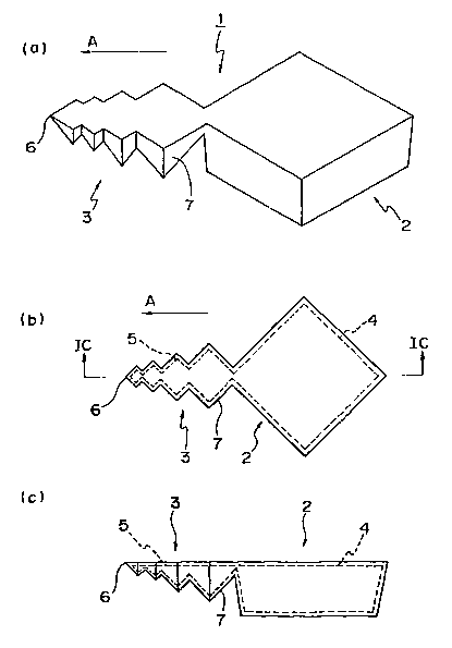
Referring Figs. 1A-1C and 2A-2B, a drug delivery
20 system of the first embodiment according to the present
invention will be described herein. The drug delivery
system 1 includes, in general, a tank member (container) 2
and an anchor member (fixer) 3 extending from the tank
member 2. Although not limited thereto, the tank member 2
has an outline of a substantially rectangular solid, in
CA 02480343 2004-09-24
21
which a chamber 4 capable of holding a medicament such as
the regenerative cells and/or factors and the anti-cancer
drug is defined. The anchor member 3 is tapered along a
longitudinal direction as indicated by "A" in Figs. lA and
1B. Also, it is secured at one end to the tank member 2,
and has a substantially sharp tip 6 at the other end. Also,
the anchor member 3 has a plurality (e.g., four) of
protruding portions 7 as shown in Figs. 1A-1C. Each of the
protruding portions 7 has an outline of a part of a
quadrangular pyramid, thus the anchor member 3 has a
configuration combining a plurality of protruding portions
7, each of which outline is a partial quadrangular pyramid
having sides different from one another. In addition, the
anchor member 3 includes a channel 5 defined therein, in
fluid communication with the chamber 4.
Both of the tank member 2 and the anchor member 3
are formed of material such as poly-lactic acid. Poly-
lactic acid is composed of biocompatible and biodegradable
polymer molecules, and hydrolyzed to be lactic acid, which
is harmless to and metabolizable for a living body. Any
other biodegradable material besides poly-lactic acid
(including for example, glue, starch, protein, and glucose)
may be used to form the tank member 2 and the anchor member
3. Thus, since the drug delivery system 1 according to the
present invention is made of biodegradable material such as
CA 02480343 2004-09-24
22
poly-lactic acid, advantageously it can be left or embedded
within a body.
In soil, poly-lactic acid is degraded by aerobic
bacteria to carbon dioxide and water, which can be
photosynthesized to obtain poly-lactic acid. This
constitutes a part of circulation circle named as a TCA
circuit. Therefore, products made of poly-lactic acid can
be disposal into the soil and realize a recycling friendly
to the ecology, thereby showing good ecology affinity and
recycling efficiency.
So far, the silicon-based material has often been
used to produce a micro-machine that can be placed within a
body, and in addition, the flexible polymer material such
as polyimide and parylene is also utilized to produce such
a micro-machine. However, the silicon-based material (e. g.,
Si, Si02, SiN), though chemically inactive to living tissue,
cannot be evacuated by itself out of a body nor remained
beside the blood vessel, because it may serve as a core
causing a thrombus. The thrombus may block the blood
vessel, as growing, and eventually lead a fatal disease
such as a brain infarction. Similarly, since polyimide and
parylene are not biodegradable material and not evacuated
by itself out of a body, those cannot be placed within a
body, neither. Therefore, like a drug delivery system
according to the present invention, it is quite beneficial
CA 02480343 2004-09-24
23
to choose biocompatible and biodegradable material such as
poly-lactic acid as a stating material for producing a
micro-machine product intended to be placed within a body.
Poly-lactic acid has mechanical characteristics including
the Young's modulus (rigidity) close to ones of polyimide
and parylene, as illustrated in Table 1. Therefore, poly-
lactic acid having biocompatibility/biodegradability and
sufficient strength is referred to as "clean plastic".
(Table 1)
Comparison of Characteristics Among
Polyimide, Parylene, and Poly-lactic Acid
Poly-lactic
Polyimide Parylene Acid
Young's Modulus
3 3.2 3.4
[GPa]
Tensile Strength 120 70 64
[MPa]
Tensile Breaking 10 200 4.1
Elongation [
Grass Transition 310 - 61
Point [C]
Melting Point [C] 450 290 173
Supplier Dupont Union Carbide Shimazu Corp.
Microsystems Corp.
Product No. PIX-3476-4L - Lacty 5000
Injection
Production ProcessSpin Coating CVD Molding
The drug delivery 'system 1 according to the
present invention has a sharp tip 6 so that, as illustrated
in Fig. 2A, it can readily be penetrated into the vessel
wall PV adjacent the infarction INF of the coronary vessel
BV by means of a pinching device secured onto the catheter
CA 02480343 2004-09-24
24
(not shown). Also, since the drug delivery system 1 is
made of biodegradable material such as poly-lactic acid,
advantageously, it can be left within the tissue of the
blood vessel wall PV without any adverse effects to the
body. Further, since the drug delivery system 1 has the
anchor member 3, it can be retained for a substantial time
period even in the blood vessel wall PV having rapid flow
of blood. Once the drug delivery system 1 is embedded
within the tissue of the blood vessel wall PV, poly-lactic
acid forming the tank member 2 and the anchor member 3 is
gently hydrolyzed to dissolve, the medicament (the
regenerative cells and/or factors for regenerating the
blood vessel) reserved in the tank member 2 can be released
in small doses for a predetermined dosing period, e.g., one
or weeks. During such a dosing period, as shown in Fig. 2B,
the bypassing blood vessel BYP complementing the infarct
vessel is formed. At this end, poly-lactic acid forming
the tank member 2 and the anchor member 3 is completely
hydrolyzed to be lactic acid which is not accumulated
within the body, thus, the drug delivery system 1 has no
need to be taken out. Although not shown, the tip 6 of the
anchor member 3 may be formed with a thinner layer of poly-
lactic acid than the remaining regions that can be
dissolved at an earlier stage. This forms an opening at
the tip 6, thereby allowing the medicament stored in the
CA 02480343 2004-09-24
chamber 4 to be gently released through the channel 5 and
the tip 6.
As described above, according to the present
invention, the drug delivery system 1 can be placed in the
5 blood vessel wall PV having rapid flow of blood for a
prolonged time so that the stored regenerative cells and/or
factors are slowly released and supplied to the body
portion requiring the medicament, thereby efficiently
forming the bypassing blood vessel BYP without the invasive
10 surgical operation.
«Manufacturing Process of DDS of First Embodiment »
Next, referring to Figs. 3A-3H through 6A-6F, a
manufacturing process of the drug delivery system of the
15 first embodiment will be described herein.
Firstly, a pair of silicon substrates 10, 11
having principal surfaces of (100) crystal plane is
prepared. As shown in Figs. 3A and 3B, one of the silicon
substrates 10 is processed to have silicon dioxide (Si02)
20 layers 12a, 12b on both surfaces and washed with sulfuric
acid/hydrogen peroxide/water (H2S04 . H202 - 3 . 1) and
ammonium hydroxide/hydrogen peroxide/water (NHqOH . H202 .
H20 = 1 . 1 . 5) for five minutes.
As shown in Fig. 3C, formed on the silicon
25 dioxide layer 12a is a photoresist layer 14, which is baked
CA 02480343 2004-09-24
26
at 90 degrees C for ten minutes.
As illustrated in Figs. 3D and 3E, the
photoresist layer l4,is patterned with a mask M1. This
mask M1 does not cover the regions of the photoresist layer
14 indicated by hatchings of Fig. 3D. Thus, the mask M1
uncovers a tank region 16 and a plurality of circle regions
18 discretely arranged in a line. Each of the circle
regions 18 is designed so as to have smaller diameter as
the center position thereof is away from the tank region 16.
In Fig. 3F, the silicon dioxide (SiOz) layer 12a
is reactive-ion etched with fluoroform gas (CHF3) (etching
condition: 5sccm, 5Pa, 100W, 1H).
Next, after the photoresist layer 14 is stripped
off, the remaining silicon dioxide layer 12a is used as a
mask for wet etching the silicon substrate 10 with
potassium hydroxide (KOH) as an etchant (etching condition:
33weight~, 70 degrees C, 55 minutes). In general, silicon
having a surface-orientation dependency (etch anisotropy)
with the etchant of potassium hydroxide is etched along the
orientation perpendicular the (111) crystal plane of
silicon. To this result, as shown in Figs. 3G and 3H, a
plurality of recesses, each of which has an outline of a
flipped quadrangular pyramid, are overlapped one another so
that an anchor recess 22 is formed. Similarly, formed in
the tank region 16 is a tank recess 20, which is in fluid
CA 02480343 2004-09-24
27
communication with the anchor recess 22.
After again forming a silicon dioxide (Si02)
layer 24 on the silicon substrate 10 having the tank recess
20 and the anchor recess 22 (referred to as "the first
silicon substrate 10", herein) as illustrated in Fig. 4A, a
thin layer 26 of poly-lactic acid is formed thereon, as
shown in Fig. 4B.
Examples to form the thin layer 26 of poly-lactic
acid include a solvent-dissolution spin coating and a heat-
melt spin coating. In the solvent-dissolution spin coating,
a solution obtained by thoroughly dissolving solid phase of
poly-lactic acid with solvent such as chloroform (CHC13) is
applied on the silicon substrate and spin-coated. Also,
the solvent is fully evaporated so as to form the thin
layer solely made of poly-lactic acid. These steps may be
repeated to control the thickness of the thin layer of
poly-lactic acid as desired. On the other hand, in the
heat-melt spin coating, liquid phase of poly-lactic acid
obtained by heating to melt solid phase of poly-lactic acid
is applied on the silicon substrate and spin-coated. Then,
it is cooled down by leaving at room temperature so that
the thin layer of poly-lactic acid is formed. Any other
processes well known by those skilled in the art may be
used to form the thin layer of poly-lactic acid.
Similarly, formed on both surfaces of another
CA 02480343 2004-09-24
28
intact silicon substrate rather than the first silicon
substrate 10, which is referred to as the second silicon
substrate 11, are silicon dioxide (Si02) layers 13a, 13b,
as shown in Fig. 4C.
In Fig. 4D, a thin layer 28 of poly-lactic acid
is also formed on one surface of the second silicon
substrate 11.
Next, as illustrated in Fig. 4E, the first and
second silicon substrates 10, 11 are laminated so that the
thin layers 26, 28 of poly-lactic acid face to each other.
Then, the first and second silicon substrates 10, 11 are
securely bonded to each other by heating thereof close to
the melting point of poly-lactic acid. Thus, the space is
defined between the thin layers 26, 28 of poly-lactic acid
to form the chamber 4 of the tank member 2 and the channel
5 of the anchor member 3.
Next, the silicon dioxide (Si02) layers 12b, 13b
are reactive-ion etched with fluoroform gas (CHF3) (etching
condition: 5sccm, SPa, 100W, 1H). Then, the silicon
substrate 10, 11 are removed, remaining the silicon dioxide
(Si02) layers, for example, by wet etching with tetra-
methyl ammonium hydroxide (TMAH) or by ion-reactive etching
with sulfur hexafluoride (SF6).
Lastly, as shown in Fig. 4G, the silicon dioxide
(Si02) layers 13a, 24 are stripped off, for example, by wet
CA 02480343 2004-09-24
29
etching with hydrofluoric acid (HF) or by ion-reactive
etching with fluoroform gas (CHF3) so as to obtain the drug
delivery system 1 of the first embodiment.
The medicament is injected into the chamber 4 of
the drug delivery system by use of any appropriate ways.
For example, a through-hole is made at a suitable position
of the tank member 2 or the anchor member 3 extending
through the chamber 4 or the channel 5 with a focused-ion-
beam system (FIB), through which the chamber 4 is filled up
with the medicament. Then, the thin layer of poly-lactic
acid around the through-hole is heated and melted to
occlude the through-hole.
As described above, the drug delivery system 1
according to the present invention can be manufactured
based upon a micro-machine technology applying the fine
processing technology of a semiconductor integrated circuit
device. Based upon the fine processing technology
currently available, the processing accuracy in the order
of manometer for a submicron structure can be realized.
Therefore, according to the micro-machine technology, the
drug delivery system 1 having any desired dimension and
configuration can be manufactured in a precise manner and
at a reasonable cost.
«Modification 1: Alternative Manufacturing Process»
CA 02480343 2004-09-24
Referring to Figs. 5A-5E and 6A-6F, an
alternative manufacturing process of the drug delivery
system of the first embodiment (first modification) will be
described herein.
5 In the alternative manufacturing process, firstly,
a silicon substrate 30 having principal surface of (100)
crystal plane is prepared. Although not shown in the
drawing as being similar to the above-mentioned process, a
silicon substrates 30 is processed to have silicon dioxide
10 (Si02) layers 32a, 32b on both surfaces and washed with
sulfuric acid/hydrogen peroxide/water (H2S09 . H20z = 3 . 1)
and ammonium hydroxide/hydrogen peroxide/water (NH40H
H202 . H20 - 1 . 1 . 5) for five minutes. Then, a
photoresist layer 34 is formed on the silicon dioxide layer,
15 which is baked at 90 degrees C for ten minutes.
Next, a mask M2 shown in Fig. 5A is used to
pattern the photoresist layer 34. This mask M2 does not
cover the regions of the photoresist layer 34 indicated by
hatchings of Fig. 5A. Thus, the mask M2 uncovers a tank
20 region 36 and a plurality of circle regions 38 discretely
arranged in a line, except of a bridge region 37 extending
through the tank region 36 and the circle regions 38. Also,
each of the circle regions 38 is formed so as to have
smaller diameter as the center position thereof is away
25 from the tank region 36.
CA 02480343 2004-09-24
31
In Fig. 5B, the silicon dioxide (Si02) layer 32a
is reactive-ion etched with fluoroform gas (CHF3) (etching
condition: 5sccm, 5Pa, 100W, 1H), and the photoresist layer
14 is stripped off. Then, the remaining silicon dioxide
layer 32a is used as a mask for wet etching the silicon
(Si) substrate 30 with potassium hydroxide (KOH) as an
etchant (etching condition: 33 weighto, 70 degrees C, 55
minutes). As described above, silicon has a surface-
orientation dependency (etch anisotropy) with the etchant
of potassium hydroxide. Therefore, as illustrated in Figs.
5C and 5D, a plurality of recesses, each of which has an
outline of a flipped quadrangular pyramid, are overlapped
one another so that an anchor recess 42 is formed.
Similarly, formed in the tank region 36 is a tank recess 40,
which is in fluid communication with the anchor recess 42.
It should be noted that the silicon dioxide (Si02) layer is
still remained in the bridge region 37, which eventually
forms the chamber 4 and the channel 5.
In Fig. 5E, another silicon dioxide (Si02) layer
44 is formed on the silicon substrate 30 having the tank
recess 40 and the anchor recess 42, and then another layer
46 of poly-lactic acid is formed thereon by pouring heated
and melted poly-lactic acid onto the silicon substrate 30
(including the tank recess 40 and the anchor recess 42).
Next, although not shown, an evaporated aluminum
CA 02480343 2004-09-24
32
(A1) layer is formed on the poly-lactic acid layer 46, on
which another photoresist layer is formed. A mask M3 shown
in Fig. 6A is used to pattern the photoresist layer. The
mask M3 is formed over the tank recess 40 including the
bridge region 37 and the anchor recess 42. The aluminum
layer is etched by phosphoric acid (H3POQ) or mixed acid
with the mask M3 to obtain a patterned aluminum thin layer
48 shown in Fig. 6B.
As illustrated in Fig. 6C, after removing the
photoresist layer, the patterned aluminum thin layer 48 is
used as a mask to remove (ash) the poly-lactic acid layer
by plasma-etching with oxygen gas (OZ), leaving the
aluminum thin layer 48. Also, the silicon dioxide (Si02)
layers 44 is reactive-ion etched with fluoroform gas (CHF3)
(etching condition: 5sccm, 5Pa, 100W, 1H).
Next, in Fig. 6D, an etchant reactive with
silicon (Si) but inactive with silicon dioxide (Si02) is
used to etch the silicon substrate 30. For example, the
silicon substrate 30 is wet etched with tetra-methyl
ammonium hydroxide (TMAH) or ion-reactive etched with
sulfur hexafluoride (SF6).
In Fig. 6E, an etchant active with aluminum but
inactive with poly-lactic acid and silicon dioxide (Si02)
such as phosphoric acid (H3P0q) and mixed acid is used to
etch the aluminum thin layer 48.
CA 02480343 2004-09-24
33
Lastly, the drug delivery device 1 is bathed into
an etchant active with silicon dioxide (Si02) but inactive
with poly-lactic acid such as hydrofluoric acid (HF), so
that the silicon dioxide (Si02) layer 44 beneath poly-
lactic acid and silicon dioxide (Si02) within the bridge
region 37 are completely removed. Thus, the drug delivery
system 1 is obtained solely made of poly-lactic acid.
The drug delivery device 1 has openings (not
shown) at positions corresponding to both ends of the
bridge region 37 shown in Fig. 5C. After filling up with
the medicament through the openings, the thin layer of
poly-lactic acid forming the tank member 2 and the anchor
member 3 is heated and melted to occlude the openings.
« Drug Delivery System of Second Embodiment»
Referring to Figs. 7A-7C, a drug delivery system
of the second embodiment according to the present invention
will be described herein. Similar to the first embodiment,
the drug delivery system 51 of the present embodiment
includes, in general, a tank member (container) 52 and an
anchor member (fixer) 53 extending from the tank member 52.
Although not limited thereto, the tank member 52 has an
outline of a rectangular solid, in which a chamber 54
capable of holding a medicament such as the regenerative
cells and/or factors and the anti-cancer drug is defined.
CA 02480343 2004-09-24
34
The anchor member 53 is tapered along a longitudinal
direction as indicated by "B" in Figs. 7A and 7B. Also, it
is secured at one end to the tank member 52, and has a
substantially sharp tip 56 at the other end. Also, the
anchor member 53 has a plurality (e. g., four) of protruding
portions 57 as shown in Figs. 7A and 73. Each of the
protruding portions 57 has an outline of a part of a
triangular prism. Either one, or preferably both of the
side surfaces of the triangular prisms extend in a
direction inclined at an obtuse angle (6) to the
longitudinal direction of "B". In addition, the anchor
member 53 includes a channel 55 defined therein, in fluid
communication with the chamber 54.
Also, similar to the first embodiment, both of
the tank member 52 and the anchor member 53 are formed of
biodegradable material such as poly-lactic acid, and the
sharp tip 56 is formed. Therefore, the drug delivery
system 51 can be embedded in a desired portion of a living
body where the treatment is required, providing no adverse
effect to the body. Also, the protruding portions 57 of
the anchor member 53 extend in a direction inclined at an
obtuse angle (8) to the embedded direction of "B" indicated
in Figs. 7A and 7B, so that once embedded into the
treatment portion, they engage with the peripheral tissue
thereof. This prevents the drug delivery system 51 from
CA 02480343 2004-09-24
being released from the treatment portion and allows it to
be secured thereon for a long time even where the treatment
portion has a rapid flow of body fluid such as blood. Thus,
poly-lactic acid forming the tank member 52 and the anchor
5 member 53 of the drug delivery system 51 is gently
hydrolyzed to dissolve, the medicament reserved in the tank
member 52 can be released in small doses for a
predetermined dosing period. Although not shown, the side
surfaces of the protruding portions 57 of the anchor member
10 53 may be formed with a thinner layer of poly-lactic acid
than the remaining regions so as to be dissolved at an
earlier stage. This forms openings at the protruding
portions 57, thereby allowing the medicament stored in the
chamber 54 to be released through the channel 55 and the
15 side surfaces of the protruding portions 57. Therefore,
like the first embodiment, the drug delivery system 51 is
used to form the bypassing blood vessel BYP complementing
the infarct vessel as shown in Fig. 2B.
20 «Manufacturing Process of DDS of Second Embodiment»
Next, referring to Figs. 8A-8G and 9A-9G, a
manufacturing process of the drug delivery system of the
second embodiment will be described herein.
Firstly, a pair of silicon substrates 60, 61 is
25 prepared. As shown in Figs. 8A and 8B, one of the silicon
CA 02480343 2004-09-24
36
substrates 60 is processed to have silicon dioxide (Si02)
layers 62a, 62b on both surfaces and washed with sulfuric
acid/hydrogen peroxide/water (HZSOq . H202 - 3 . 1) and
ammonium hydroxide/hydrogen peroxide/water (NHqOH . H202 .
H20 = 1 . 1 . 5) for five minutes.
As shown in Fig. 8C, applied on the silicon
dioxide layer 62a is a photoresist layer 64, which is baked
at 90 degrees C for ten minutes.
As illustrated in Figs. 8D and 8E, the
photoresist layer 64 is patterned with a mask M4. This
mask M4 does not cover the regions of the photoresist layer
64 indicated by hatchings of Fig. 8D. Thus, the mask M4
uncovers a tank region 66 having a substantially
rectangular shape and an anchor region 68 having a shape
overlapping two pairs of flukes.
In Fig. 8F, the silicon dioxide (Si02) layer 62a
is reactive-ion etched with fluoroform gas (CHF3) (etching
condition: 5sccm, 5Pa, 100W, 1H).
Next, after the photoresist layer 64 is stripped
off, the remaining silicon dioxide layer 62a is used as a
mask for reactive-ion etching the silicon substrate 60 with
sulfur hexafluoride (SF6) (etching condition: 50sccm, 20Pa,
100W, 45minutes). To this result, as shown in Figs. 8G, a
recess 70 of a predetermined depth having a tank recess and
the an anchor recess is formed in the tank region 66 and
CA 02480343 2004-09-24
37
the anchor region 68 in fluid communication with each other.
After again forming a silicon dioxide (Si02)
layer 72 on the silicon substrate 60 having the recess 70
(referred to as "the first silicon substrate 60", herein)
as illustrated in Fig. 9A, a thin layer 74 of poly-lactic
acid is formed thereon as shown in Fig. 9B, by the above-
mentioned solvent-dissolution spin coating or the heat-melt
spin coating.
Also, as shown in Fig. 9C, silicon dioxide (Si02)
layers 63a, 63b are formed on both surfaces of another
intact silicon substrate 61 rather than the first silicon
substrate 60, which is referred to as the second silicon
substrate.
In Fig. 9D, a thin layer 76 of poly-lactic acid
is also formed on one surface of the second silicon
substrate 61.
Next, as illustrated in Fig. 9E, the first and
second silicon substrates 60, 61 are laminated so that the
thin layers 74, 76 of poly-lactic acid are faced to each
other. Then, the first and second silicon substrates 60,
61 are securely bonded to each other by heating thereof
close to the melting point of poly-lactic acid.
Next, in Fig. 9F, the silicon aioxlae (~iU2)
layers 62b, 63b are reactive-ion etched with fluoroform gas
(CHF3) (etching condition: 5sccm, 5Pa, 100W, 1H). Then,
CA 02480343 2004-09-24
38
the silicon substrate 60, 61 are removed, remaining the
silicon dioxide (Si02) layers 63a, 72, for example, by wet
etching with tetra-methyl ammonium hydroxide (TMAH) or by
ion-reactive-etching with sulfur hexafluoride (SF6).
Lastly, as shown in Fig. 9G, the silicon dioxide
(Si02) layers 63a, 72 are stripped off with an etchant
inreactive with poly-lactic acid but reactive with silicon
dioxide (Si02). For example, it is wet etched with
hydrofluoric acid (HF) or by dry-etched with fluoroform gas
(CHF3) so as to realize the drug delivery system 51 of the
second embodiment.
Also, the medicament is injected into the drug
delivery system chamber by use of any appropriate means.
For example, a through-hole is made at a suitable position
of the tank member 52 or the anchor member 53 extending
through the chamber 54 or the channel 55 with a focused-
ion-beam system (FIB), through which the chamber 54 is
filled up with the medicament. Then, the thin layer of
poly-lactic acid around the through-hole is heated and
melted to occlude the through-hole.
«Modification 2: Alternative Manufacturing Process»
With reference of Figs. l0A-10E, an alternative
manufacturing process of the drug delivery system of the
second embodiment (second modification) will be described
CA 02480343 2004-09-24
39
herein.
In the alternative manufacturing process, firstly,
a silicon substrate 60 is prepared and processed as
described above with reference of Figs. 8A-8G.
Then, the recess 70 having a predetermined depth
in the tank region 66 and the anchor region 68 of the mask
M4 is filled up with melted aluminum.
Silicon is etched off to obtain a micro molding
die 78 of aluminum (A1) having a configuration similar to
the drug delivery system of the second embodiment, as
illustrated in Figs. 10B and lOC.
The micro molding die 78 is immersed into melted
poly-lactic acid and drawn up, and then left at room
temperature to form a thin layer 80 of poly-lactic acid
encompassing the micro molding die 78.
Similarly, a through-hole 82 is made at a
suitable position of the tank member 52 or the anchor
member 53 with a focused-ion-beam system (FIB) so that a
portion of the micro molding die 78 is exposed as shown in
Fig. 10E. Then, the micro molding die 78 is immersed into
an etchant solution active with aluminum but inactive with
poly-lactic acid such as phosphoric acid (H3P09) to form
the drug delivery system 51 having an opening 82. Lastly,
the medicament is injected into the drug delivery system
through the opening 82, and then, the thin layer of poly-
CA 02480343 2004-09-24
lactic acid around the opening 82 is occluded by heating
and melting.
«Drug Delivery System of Third Embodiment »
5 A drug delivery system of the third embodiment
according to the present invention will be described herein.
This drug delivery system 51 having a structure similar to
one of the second embodiment except that the anchor member
53 has no channel 55 in fluid communication with the
10 chamber 54 of the tank member 52, thus duplicate
description will be eliminated herein.
According to the drug delivery system 51 so
structured, the chamber 54 of the tank member 52 can
preserve a medicament such as the regenerative cells and/or
15 factors and the anti-cancer drug. Also, once embedded into
the treatment portion, the protruding portions 57 of the
anchor member 53 engage with the peripheral tissue thereof.
This prevents the drug delivery system 51 from being
released from the treatment portion and allows it to be
20 secured thereon for a long time even where the treatment
portion has a rapid flow of body fluid such as blood. Thus,
as poly-lactic acid forming the tank member 52 and the
anchor member 53 of the drug delivery system 51 is gently
hydrolyzed to dissolve, the medicament reserved in the tank
25 member 52 can be released in small doses for a
CA 02480343 2004-09-24
41
predetermined dosing period.
«Manufacturing Process of DDS of Third Embodiment»
Referring to Figs. 11A-11G and 12A-12H, a
manufacturing process of the drug delivery system 51 of the
third embodiment will be described herein.
In the manufacturing process, a silicon substrate
80 is prepared and processed to have silicon dioxide (Si02)
layers 82a, 82b on both surfaces and washed with sulfuric
acid/hydrogen peroxide/water (HZS04 . H202 - 3 . 1) and
ammonium hydroxide/hydrogen peroxide/water (NH40H . H202 .
H20 = 1 . 1 . 5) for five minutes..
Then, a photoresist layer 84 is applied on the
silicon dioxide layer, which is baked at 90 degrees C for
ten minutes.
Next, a mask M5 shown in Fig. 11D is used to
pattern the photoresist layer 84. This mask M5 does not
cover the regions of the photoresist layer 34 indicated by
hatchings of Fig. 11D. Thus, the mask M5 uncovers a
peripheral portion 87 of a tank region 86 and an anchor
region 88 having a shape overlapping two pairs of flukes.
However, it covers a middle portion 89 of the tank region
86.
In Fig. 11F, the silicon dioxide (Si02) layer 82a
is reactive-ion etched with fluoroform gas (CHF3) (etching
CA 02480343 2004-09-24
42
condition: 5sccm, 5Pa, 100W, 1H).
After the photoresist layer 84 is stripped off,
the remaining silicon dioxide layer 32a is used as a mask
for reactive-ion etching the silicon (Si) substrate with
sulfur hexafluoride (SF6) (etching condition: 50sccm, 20Pa,
100W, 45minutes). To this result, as shown in Figs. 11G,
the silicon substrate is recessed in the peripheral portion
87 of the tank region 86 and the anchor region 88 to have a
recess 90 of a predetermined depth in fluid communication
to each other.
As shown in Fig. 12A, a silicon dioxide (Si02)
layer 92 is again formed on the silicon substrate 80. Then,
as shown in Fig. 12B, the recess 90 formed in the
peripheral portion 87 of the tank region 86 and the anchor
region 88 is filled up with melted poly-lactic acid, so as
to form a thin layer 94 of poly-lactic acid.
Next, although not shown in the drawing, aluminum
(A1) is deposited on the thin layer 94 of poly-lactic acid
to form an aluminum layer, on which in turn a photoresist
layer is formed. Then, a mask shown in Fig. 12C is used to
cover the tank region 86 and the anchor region 88. The
aluminum layer is etched by phosphoric acid (H3P0q) or
mixed acid with the mask M6 to obtain a patterned aluminum
thin layer 48 shown in Fig. 12D.
As illustrated in Fig. 12E, the patterned
CA 02480343 2004-09-24
43
aluminum thin layer 96 is used as a mask to remove (ash)
the poly-lactic acid layer by plasma-etching with oxygen
gas (OZ). Also, the silicon dioxide (Si02) layer 94 is
reactive-ion etched with fluoroform gas (CHF3) (etching
condition: 5sccm, 5Pa, 100W, 1H).
Next, in Fig. 12F, an etchant active with silicon
(Si) but inactive with silicon dioxide (Si02) is used to
etch the silicon substrate 80. For example, the silicon
substrate 30 is wet etched with tetra-methyl ammonium
hydroxide (TMAH) or ion-reactive etched with sulfur
hexafluoride (SF6) .
In Figs. 12G and 12H, an etchant reactive with
aluminum but inactive with poly-lactic acid and silicon
dioxide (Si02), such as phosphoric acid (H3P09) and mixed
acid is used to etch the aluminum thin layer 96. Lastly,
the silicon dioxide layer 82b beneath poly-lactic acid is
etched and removed by the reactive-ion etching with
fluoroform gas (CHF3) (etching condition: 5sccm, 5Pa, 100W,
1H) so as to obtain an intermediate structure solely made
of poly-lactic acid shown in Fig. 12H. The structure of
Fig. 12H is illustrated as being flipped of Fig. 12F.
The structure solely made of poly-lactic acid has
an opening 98 uncovered in the region corresponding to the
tank member 52, allowing the medicament to be injected
through the opening 98. After injection, another thin
CA 02480343 2004-09-24
44
layer of poly-lactic acid (not shown) is used to cover the
opening 98, and then those are sealed by heating and
depressing to each other so as to obtain the drug delivery
system 51 having the medicament sealed within the chamber
54.
The anchor member 53 of the third embodiment
manufactured by the present process has no channel 55 and
is filled with poly-lactic acid, therefore, it is
manufactured as being a solid type of the drug delivery
system. However, a hollow type of the drug delivery system,
similar to one of the second embodiment, can also be
produced by designing the mask M5 to cover a middle portion
of the anchor region 88 as well.
In addition, the tank member 52 may be formed to
have no chamber and fully filled up with poly-lactic acid
as being solid type of the tank member as well as the
anchor member 53. However, in this case, the medicament
should have been impregnated within the poly-lactic acid
material composing the drug delivery system in advance.
Once the drug delivery system 51 made of such a poly-lactic
acid material containing the medicament is placed within a
body, the medicament impregnated therein is slowly released
as the poly-lactic acid material is gently hydrolyzed to
dissolve, thus the same advantage can be expected as the
above embodiments.
CA 02480343 2004-09-24
« Drug Delivery System of Fourth Embodiment »
Referring to Figs. 13A-13C and 14A-14D, a drug
delivery system of the fourth embodiment according to the
5 present invention will be described herein. This drug
delivery system 51 having a structure similar to one of the
second embodiment except that the tank member 52 is
eliminated, thus duplicate description will be eliminated
herein.
10 In the drug delivery system 51, the chamber 54
holding the medicament such as the regenerative cells
and/or factors and the anti-cancer drug is defined within
the anchor member 53. Although Figs. 13A-13C illustrate
the drug delivery system 51 having six protruding portions
15 57, it may include more or less of protruding portions 57.
As those skilled in the art would realize, the drug
delivery system 51 may be formed by any manufacturing
processes described above in the second embodiment.
Also, although the drug delivery system 51 of the
20 present embodiment is produced as a hollow type of the
anchor member 53 as the second embodiment, it may also be
designed as a sold type of the anchor member 53 as the
third embodiment. In this case, the solid type of the
anchor member 53 is formed of poly-lactic acid material
25 containing the medicament as described above in the third
CA 02480343 2004-09-24
46
embodiment.
The drug delivery system 51 solely made from the
hollow and solid type of the anchor member 53 can be
modified in many applications. For example, a solid
medicine 58 in a tablet form may directly be fixed on one
end opposite to the tip 56.
Alternatively, the tank member having the chamber
made of poly-lactic acid may separately be formed by any
processes as those skilled in the art can realize, and then
pressed and adhered onto the anchor member 53 of the
present embodiment to form the drug delivery system.
Besides, the anchor member and the tank member of poly
lactic acid may readily be adhered with other appropriate
biodegradable material such as glue, starch, protein, and
glucose.
Also, a plurality of anchor members may be
adhered on a single tank member extending in the same
direction as shown in Fig. 14B or extending in the
different directions as illustrated in Fig. 14C. Further,
as shown in Fig. 14D, two of the anchor members are
combined so that the sharp tips are arranged on both ends
in the longitudinal direction.
« Drug Delivery System of Fifth Embodiment »
Referring to Figs. 15A-15B, a drug delivery
CA 02480343 2004-09-24
47
system according to the fifth embodiment will be described
herein. In Figs. 15A-15B, the drug delivery system 101
includes, in general, a plurality of tank members
(containers) 102 (five of nine tank members are shown
herein), a connecting member (connector) 103 for connecting
adjacent tank members 102, a cap member 104 for
hermetically sealing each of the tank members 102, and a
plurality of anchor members (fixers) 105 extending from the
respective one of the tank members 102. Each of the tank
members 102 has an outline of a rectangular solid, in which
a chamber 106 capable of holding a medicament is defined.
Each of the anchor members 105 is tapered along a
longitudinal direction as indicated by "C" in Figs. 15A-15B,
and each has one end secured to the respective one of the
tank members 102, and the other end having a sharp tip 107.
Also, the anchor member 103 has a plurality (e.g., four) of
protruding portions 108 as shown in Figs. 15A-15B. Each of
the protruding portions 108 may have an outline similar to
those of the second and third embodiments and may be
designed as being solid or hollow.
All of the components of the drug delivery system
101 are made of biodegradable material such as poly-lactic
acid similar to the first to fourth embodiments, and each
of the anchor members 105 has the sharp tip 107. Therefore,
the drug delivery system 101 can be embedded into the
CA 02480343 2004-09-24
48
desired portion (treatment portion) without any adverse
effects to a body. Also, since each of the anchor members
105 has the protruding portions 108, once embedded into the
treatment portion, the protruding portions 108 engage with
the peripheral tissue thereof. This prevents the drug
delivery system 101 from being released from the treatment
portion and allows it to be secured thereon for a long time
even where the treatment portion has a rapid flow of body
fluid such as blood. Thus, poly-lactic acid forming the
tank member 102 and the anchor member 105 of the drug
delivery system 101 is gently hydrolyzed to dissolve, the
medicament reserved in the tank member 52 can be released
in small doses for a predetermined dosing period.
Although not shown, the side surface of each of
the tank members 102 may have a layer of poly-lactic acid
adjusted such that the timing for releasing the medicaments
stored within the tank members 102 is controlled. Thus,
various types of medicaments in different tank members 102
can be released at the different timings. For example, the
regenerating cells for inducing the regeneration of the
blood vessel are stored in the chamber 106 of the tank
member 102 having the thinner side surface, and the
regenerating factors for growing the regenerating cells are
held within the chamber 106 of the tank member 102 having
thicker side surface, which releases the medicament at a
CA 02480343 2004-09-24
49
later timing. Thus, the regenerating cells induces the
regeneration of the blood vessel and after some appropriate
time has passed, the regenerating factors control the
regenerating cells to regenerate the blood vessel in an
effective manner. Also, a plurality of the tank members
102 may be designed such that the same type the medicament
is released at different timings. This allows a longer
dosing period of the same medicament.
«Manufacturing Process of DDS of Fifth Embodiment»
Next, referring to Figs. 16A-16F and 17A-17C, a
manufacturing process of the drug delivery system of the
fifth embodiment will be described herein.
Firstly, a pair of silicon substrates 110, 120 is
prepared. The silicon substrates 110, 120 are processed
with the micro photolithography as described above to form
recesses 112, 122 of different shapes thereon a~
illustrated in Fig. 16A and 16B, respectively.
Next, melted aluminum is molded into the recesses
112, 122 as illustrated in Figs. 16C and 16D.
The silicon substrate 110, 120 are removed by wet
etching with tetra-methyl ammonium hydroxide (TMAH) or by
ion-reactive etching with sulfur hexafluoride (SF6) to
obtain the aluminum molding dice 114, 124, as shown in Figs.
16E and 16F. It should be noted that Fig. 16F illustrates
CA 02480343 2004-09-24
the aluminum molding die 124 as flipped over in Fig. 16D.
As illustrated in Fig. 17A, the recess of the
aluminum molding die 124 is filled up with melted poly
lactic acid 130 and then the aluminum molding die 114 is
5 inserted into the aluminum molding die 124 as shown in Fig.
17B. Poly-lactic acid 130 is hardened by leaving at room
temperature.
Next, phosphoric acid (H3P04) or mixed acid is
used to etch the aluminum molding dice 114, 124 to form the
10 tank member 102 and the connector member 103 connecting
adjacent tank members 102.
A plurality of anchor members 105 separately
prepared according to the third embodiment are adhered onto
at least one, preferably all of the bottom surfaces of the
15 tank members 102 with any appropriat a biodegradable
material, such as glue, starch, protein, and glucose.
Lastly, after any suitable medicaments are fed
into each of the tank members 102 through the upper
openings 132, all of which in turn are covered and
20 hermetically sealed by a thin layer of poly-lactic acid
separately prepared.
« Drug Delivery System of Sixth Embodiment »
Referring to Figs. 18A-18D, a drug delivery
25 system according to the sixth embodiment will be described
CA 02480343 2004-09-24
51
herein. In general, the drug delivery system 201 is
composed of a plurality (e. g., two) of anchor members 210,
220 combined together, as illustrated in Figs. 18A-18D.
The anchor members 210, 220 each have an outline of a prow
of a boat and include chambers 212, 222 defined inside,
respectively, for holding the medicament such as the
regenerative cells and/or factors and the anti-cancer drug.
Although the chambers 212, 222 are illustrated as being in
fluid communication with each other, they may be designed
to. be separated. If the chambers 212, 222 are separated,
the different type of the medicaments can be preserved in
those chambers 212, 222.
Also, although each of the anchor members 210,
220 is illustrated as being a hollow type, i.e., having the
chamber therein, it may be a solid type, which is fully
filled up with poly-lactic acid. In this case, as
described in the fourth embodiment in Fig. 14A, a solid
medicine in a tablet form may directly be fixed on one end
opposite to the tip 226 of the anchor member 210.
Alternatively, as illustrated in Figs. 14B and 14C, a tank
member of poly-lactic acid separately prepared may be
bonded to the anchor member 220 in an appropriate bonding
ways, for example, by using glut or by exposing xenon beam
to the local point for heating and melting.
Also, each of the anchor members 210, 220 has a
CA 02480343 2004-09-24
52
pair of fin-like protruding portions 214a, 214b and 224a,
224b. In the top plan view of the drug delivery system 201
shown in Fig. 18B, each of side lines of the protruding
portions 214a, 214b and 224a, 224b is designed such that it
is inclined to a longitudinal direction indicated by an
arrow D at approximately 35.3 degrees (cp - n/2 -
arctan(~I2)). Also, in the cross sectional view shown in
Fig. 18D, each side line defining the protruding portions
214a, 214b and 224a, 224b of the anchor members 210, 220,
except the upper surface 225, is inclined to the
longitudinal direction at approximately 35.3 degrees (cp -
n/2 - arctan(~2)). Thus, each of the protruding portions
214 and 224a extends rearwardly to the longitudinal
direction D, and has a substantially sharp tip 226 in the
cross sectional view as well as the top plan view.
In the foregoing description, the drug delivery
system 201 has only two anchor members 210 220- combined
together, but it may be designed to have only one anchor
member or three or more anchor members.
Also, similar to the first embodiment, the anchor
members 210, 220 are formed of biodegradable material such
as poly-lactic acid, and the sharp tip 226 is formed.
Therefore, the drug delivery system 201 can be embedded in
a desired portion of a living body where the treatment is
required, providing no adverse effect to the body. Also,
CA 02480343 2004-09-24
53
the anchor members 210, 220 have the protruding portions
214, 224 inclined to the penetration direction (the arrow
direction D in Figs. 18A-18D) at an obtuse angle (n - ~).
Therefore, once embedded into the treatment portion, the
protruding portions 214, 224 engage with the peripheral
tissue thereof. This prevents the drug delivery system 201
from being released from the treatment portion and allows
it to be secured thereon for a long time even where the
treatment portion has a rapid flow of body fluid such as
blood. Thus, poly-lactic acid forming the anchor members
210, 220 of the drug delivery system 201 is gently
hydrolyzed to dissolve, the medicament held within the
chambers 212, 222 can be released in small doses for a
predetermined dosing period. Thus, similar to the first
embodiment, the drug delivery system 201 is used to form
the bypassing blood vessel BYP complementing the infarct
vessel as shown in Fig. 2B.
«Manufacturing Process of DDS of Sixth Embodiment»
Referring to Figs. 19A-19G, a manufacturing
process of the drug delivery system 201 of the sixth
embodiment will be described herein.
Contrary to the manufacturing process of the
first embodiment, a silicon substrate 230 having principal
surfaces of (110) crystal plane is prepared. As shown in
CA 02480343 2004-09-24
54
Figs. 19A and 19B, the silicon substrates 10 is processed
to have silicon dioxide (Si02) layers 232a, 232b on both
surfaces and washed with sulfuric acid/hydrogen
peroxide/water (H2S04 . HZOz - 3 . 1) and ammonium
hydroxide/hydrogen peroxide/water (NH90H . HzOz . H20 = 1
1 . 5) for five minutes.
A photoresist layer is applied on the silicon
dioxide layer and baked at 90 degrees C for ten minutes.
Then, a mask M7 shown in Figs. 19C and 19D is used to
pattern the photoresist layer 234. This mask M7 does not
cover the regions of the photoresist layer 234 indicated by
hatchings of Fig. 19C. Thus, the mask M7 uncovers chamber
regions 236 and fin regions 238. All of the sides
constituting the mask M7 are designed such that they are
inclined to the <100> crystal orientation D' of the silicon
substrate at approximately 35.3 degrees (cp - n/2 -
arctan(~2)).
In Fig. 19E, the silicon dioxide (Si02) layer
212a is reactive-ion etched with fluoroform gas (CHF3)
(etching condition: 5sccm, 5Pa, 100W, 1H).
Next, after the photoresist layer 14 is stripped
off, the remaining silicon dioxide layer 232a is used as a
mask for wet etching the silicon substrate 230 with
potassium hydroxide (KOH) as an etchant (etching condition:
33 weighto, 70 degrees C, 55 minutes). As described above,
CA 02480343 2004-09-24
silicon having a surface-orientation dependency (etch
anisotropy) with the etchant of potassium hydroxide (KOH)
is etched along the orientation perpendicular the (111)
crystal plane of silicon. To this result, as shown in Figs.
5 19F and 19G, the silicon substrate having the principal
surface of the (110) crystal plane is etched beneath the
mask M7 along the side surface 240 perpendicular to the
(110) crystal plane and inclined to the <100> crystal
orientation D' of the silicon substrate at approximately
10 35. 3 degrees (cp - n/2 - arctan ('~2) ) , and along the bottom
surface 242 inclined to the <100> crystal orientation D' of
the silicon substrate at approximately 35.3 degrees (cp -
n/2 - arctan(~12)). Thus, a chamber recess 244 is formed in
the chamber region 236 as indicated by a solid line, and a
15 fin recess 246 is formed in the fin region 238 as indicated
by an imaginary line. The chamber recess 244 and the fin
recess 246 together are referred to as an anchor recess 250.
Similar to the manufacturing process of the drug
delivery system of the first embodiment (see Figs. 4A-4G),
20 the silicon substrate 230 having the anchor recess 250 is
laminated with another silicon substrate separately
prepared with silicon dioxide (Si02) layers and a thin
layer of poly-lactic acid thereon, which is etched with
several etchants subsequently. This eventually realizes
25 the drug delivery system 201 of poly-lactic acid. The
CA 02480343 2004-09-24
56
thickness of the thin layers of poly-lactic acid may be
controlled to have each of the chambers 212, 222 to be
communicated or separated.
Alternatively, as those skilled in the art can
easily conceive, the silicon substrate 230 having the
anchor recess 250 is used to obtain the drug delivery
system 201 by another manufacturing process similar to one
of the second embodiment (see Figs. 10A-10E).
The drug delivery system 201 so formed can safely
be placed within a body for a long period so as to release
the medicament in small doses.
In the foregoing, the drug delivery system is
used for treating the circulatory system disease (forming
the bypassing blood vessel). Yet, it can be applied for
other diseases. Some of other applications of the drug
delivery system will be described herein.
1) Regeneration of cornea
When a cornea is damaged by an ophthalmologic
disease such as a cataract or glaucoma and/or an accident,
the cornea has to be regenerated for treatment. To
efficiently regenerating the cornea, the regenerative cells
and/or factors for regeneration of the cornea should
constantly be supplied to the damaged portion of the cornea.
Eye-drops can be used for supplying the regenerative cells
and/or factors, however, fresh tears are always circulating
CA 02480343 2004-09-24
57
in the eye so that most of the regenerative cells and/or
factors supplied with eye-drops would immediately run away
without staying in the eye. However, according to the drug
delivery system of the present invention can be embedded
directly into the cornea tissue, so as to constantly and
stably supply the regenerative cells and/or factors to the
damaged portion of the cornea.
2) Treatment of brain disease (Parkinson's disease)
The Parkinson's disease is believed to be
developed from the fact that dopamine of the corpus
striatum is deficient due to a striatonigral degeneration
where dopaminergic neuron cells are degenerated and
defected. The medical treatment currently available for
the disease is oral dosing of the medicaments including L-
dopa agent being modified into dopamine in the corpus
striatum, dopamine agonist serving as dopamine,
anticholinergic agent improving the balance of dopamine and
acetylcholine, and the combination thereof, in order to
improve the dopamine deficiency. However, since those
medicament orally dosed are diluted in a body, much more
amount of the medicament has to be taken into the body.
Then, the L-dopa agent causes side effects such as an
involontary movement. Thus, the drug delivery system of
the present invention is placed within the treatment
portion to gently and stably release a desired amount of
CA 02480343 2004-09-24
58
the medicament only to a portion where the treatment is
required, for a long time period.
3) Treatment of osseous disease (osteoporosis)
The most effective treatment for the osseous
diseases such as the bone fracture and the osteoporosis is
believed to directly dose the bone growing factors to the
treatment portion. Thus, the drug delivery system
according to the present invention can be placed at the
treatment portion to supply the bone growing factors in a
stable manner.
4) Bone growth for orthopaedic and aesthetic plastic
surgery
To restore a depressed fracture of a natural
skull bone in an accident, an artificial skull bone of
plastic material may be implanted. In this instance, the
drug delivery system according to the present invention can
be used to supply the regenerative factors to the portion
of the depressed fracture for regeneration of the natural
skull bone. Also, in the aesthetic plastic surgery for
extension of a nose, typically, an artificial product such
as silicone rubber is implanted into the nose: It is
possible to grow the natural nose bone by using the drug
delivery system of the invention, thereby to slowly release
the regenerative factors for bone growth in small doses for
a long time. Advantageously, the nose bone can grow slowly
CA 02480343 2004-09-24
59
so that no body will recognize the nose bone is extending
in such a way.
In the present invention, poly-lactic acid can be
used not only for manufacturing the drug delivery system
but also other medical devices. Recently, an increase in
number of patients having allergenic contact-type
dermatitis, in which a skin contacts and rejects metal
thereby to irritate, has been reported. It is desirable
for those patients to avoid the use of the stainless needle.
Although a needle coated with titanium has been proposed,
it is quite expensive. According to the present invention,
a new needle coated with poly-lactic acid can be provided,
which is manufactured by dipping the existing stainless
needle into melted poly-lactic acid to form a thin layer of
poly-lactic acid on the metal. Therefore, the present
invention can be utilized in various medical devices of
poly-lactic acid, exploiting the advantage of poly-lactic
acid.