Language selection

Search

Patent 2480547 Summary

Third-party information liability

Some of the information on this Web page has been provided by external sources. The Government of Canada is not responsible for the accuracy, reliability or currency of the information supplied by external sources. Users wishing to rely upon this information should consult directly with the source of the information. Content provided by external sources is not subject to official languages, privacy and accessibility requirements.

Claims and Abstract availability

Any discrepancies in the text and image of the Claims and Abstract are due to differing posting times. Text of the Claims and Abstract are posted:

  • At the time the application is open to public inspection;
  • At the time of issue of the patent (grant).
(12) Patent Application: (11) CA 2480547
(54) English Title: FILTER CARTRIDGE AND PROCESS FOR THE PRODUCTION THEREOF
(54) French Title: CARTOUCHE FILTRANTE ET SON PROCEDE DE PRODUCTION
Status: Deemed Abandoned and Beyond the Period of Reinstatement - Pending Response to Notice of Disregarded Communication
Bibliographic Data
(51) International Patent Classification (IPC):
  • B01D 39/16 (2006.01)
  • B01D 29/33 (2006.01)
  • B01D 37/02 (2006.01)
  • B01D 39/00 (2006.01)
  • B01D 39/14 (2006.01)
  • B01D 39/20 (2006.01)
(72) Inventors :
  • ASCHER, RALF (Germany)
  • SCHNIEDER, GEORG (Germany)
  • SCHMID, NIKOLAJ (Germany)
(73) Owners :
  • PALL CORPORATION
(71) Applicants :
  • PALL CORPORATION (United States of America)
(74) Agent: MARKS & CLERK
(74) Associate agent:
(45) Issued:
(86) PCT Filing Date: 2003-06-05
(87) Open to Public Inspection: 2003-12-18
Availability of licence: N/A
Dedicated to the Public: N/A
(25) Language of filing: English

Patent Cooperation Treaty (PCT): Yes
(86) PCT Filing Number: PCT/EP2003/005890
(87) International Publication Number: EP2003005890
(85) National Entry: 2004-09-24

(30) Application Priority Data:
Application No. Country/Territory Date
102 24 878.8 (Germany) 2002-06-05

Abstracts

English Abstract


For the filtration of liquids used in, say, the food industry, use is made of
filters of a polymeric substance that is resistant to chemicals and water.
Filter cartridges are known which have been produced by sintering or fusing
particles of said substance together and which exhibit a porous layer of
specific thickness. In order to make the production of filtration plants more
economical and to simplify filtration, the invention proposes that the layer
(2) exhibits a structure which has progressively smaller pore sizes, as
measured in the direction of flow (10), and filter aids (3) are incorporated
in said porous layer (2) and are introduced into, and anchored in, said porous
layer (2) by means of preconditioning.


French Abstract

On utilise, pour la filtration de liquides utilisés, par exemple, dans l'industrie alimentaire, des filtres en une substance polymère qui est résistante aux produits chimiques et à l'eau. On connaît déjà des cartouches filtrantes produites par frittage ou fusion de particules de ladite substance, et présentant une couche poreuse d'épaisseur spécifique. En vue d'obtenir des postes de filtration plus économiques et de simplifier la filtration, l'invention est caractérisée en ce que la couche (2) présente une structure dotée de pores ayant des dimensions qui, mesurées dans le sens de l'écoulement (10), vont progressivement en diminuant, et en ce que des auxiliaires de filtration (3) sont incorporés dans ladite couche poreuse (2) et sont introduits et ancrés dans celle-ci (2) au moyen d'un préconditionnement.

Claims

Note: Claims are shown in the official language in which they were submitted.

-6-
Claims
1. A filter cartridge (1) of a material resistant to chemicals and water,
comprising a porous layer (2) of a predefined thickness (d), formed by
bonding, especially sintering or fusing particles of said material together,
said layer (2) having a structure showing a progressively decreasing pore
size, as measured in the direction of flow (10), said layer comprising at
least one filter aid (3) incorporated in said porous layer (2), which filter
aid
is disposed in the porous layer (2) by means of preconditioning.
2. The filter cartridge of claim 1, wherein the filter accelerator is fixed or
anchored in the pores of said layer (2).
3. The filter cartridge as defined in claim 1 or 2, wherein said filter aid
(3) is,
as viewed in the direction of flow (10) through the filter cartridge (1),
disposed in a region measuring not more than two-thirds of the thickness
(d) of said layer (2), beginning at the inflow side (8).
4. The filter cartridge as defined in any one of claims 1 to 3, wherein the
pore
diameters in said porous layer (2) range from 0.5 µm to 100 µm.
5. The filter cartridge as defined in any one of claims 1 to 4, wherein said
layer (2) comprises a mixture of various filter aids (3).
6. The filter cartridge as defined in any one of claims 1 to 5, wherein
stabilizing means are additionally incorporated in said layer (2).
7. The filter cartridge as defined in any one of claims 1 to 6, wherein
activated carbon, adsorbents, and/or resins are incorporated in said layer
(2).

-7-
8. The filter cartridge as defined in any one of claims 1 to 7, wherein said
material is a polymeric material selected from polypropylene, polyethylene,
polyamide, polysulfone, polyether sulfone, polyetherfluoroethylene and
fiberglass-reinforced polypropylene.
9. The filter cartridge as defined in any one of claims 1 to 7, wherein the
material used is a metal.
10. The filter cartridge as defined in any one of claims 1 to 9, wherein a
supporting structure (5) is disposed on the outflow side of said layer (2).
11. The filter cartridge as defined in any one of claims 1 to 10, wherein said
porous layer (2) is in the form of a tubular member (12) forming a candle
filter (11).
12. The filter cartridge as defined in claim 11, wherein the wall thickness of
the
tubular member (12) defines the thickness (d) of said layer (2) and is
equal to at least 0.05 times the diameter (D) of the cartridge (1).
13. The filter cartridge as defined in claim 12, wherein the wall thickness or
thickness (d) ranges from 0.2 to 0.35 times the diameter (D).
14. A process for the production of a filter cartridge consisting of a
material
resistant to chemicals and water, in which particles of said material are
bonded, expecially sintered or fused together in such a manner that a
layer (2) of predefined thickness is formed, such that the pore sizes
progressively decrease in the direction of flow (10) of the liquid to be
filtered, wherein at least one filter aid (3) is fed to the porous layer (2)
and
incorporated by means of preconditioning in the pores (4) of said layer (2).

-8-
15. The process as defined in claim 14, wherein the filter aid (3) is fixed or
anchored in the pores of said layer (2).
16. The process as defined in claim 14 or 15, wherein the filter aid (3) is
fed to
the porous layer (2) with the aid of a liquid, preferably water.
17. The process as defined in claim 14 or 15, wherein the filter aid is fed to
the
porous layer with the aid of a gaseous fluid, preferably air.

Description

Note: Descriptions are shown in the official language in which they were submitted.


CA 02480547 2004-09-24
WO 03/103800 PCT/EP03/05890
Filter cartridge and process for the production thereof
The invention relates to a filter cartridge of a material resistant to
chemicals and
water and to a process for the production thereof.
In many industrial fields use is made of precoat and cake filtration,
particularly in
the food industry, brewing industry, chemical and pharmaceutical industries,
and
the bioprocess industry. The filters used for this purpose are frequently
filter
candles mounted in a tank-like housing either standing on, or suspended from,
a
false bottom. EP 0 032 228 A2 describes the use of porous filter tubes in
precoat
candle-type filters. These filter tubes are made up of particles sintered
together
and consisting of a high-molecular plastics substance resistant to chemicals
and
water. In order to avoid rapid blocking due to penetration of the precoat into
the
pores of the porous filter tubes, the filter cartridge has low porosity on its
inflow
side, an arrangement which also makes for easier cleaning, since the precoat
layer or the filter cake can be more readily removed by backwashing during the
cleaning operation.
In filtration processes in which both the filtered liquid and the filter cake
are
desirable products, the use of fiilter aids is not possible because the
presence of
filter aid in the cake is undesirable. This excludes the use of the filter
cake as a
product.
It is an object of the present invention to provide a filter cartridge, with
the aid of
which the downtime to commencement of filtration is shortenened and by means
of which two filtering actions can be carried out simultaneously. A further
object
of the invention is to provide a process for the production of such a fitter
cartridge.

CA 02480547 2004-09-24
WO 03/103800 PCT/EP03/05890
-2-
This object is achieved with a filter cartridge having the features of claim
1, and
by a process having the features of claim 11.
An advantage of the present invention is that the pore size of the filter
cartridge
diminishes progressively from the non-filtrate side toward the filtrate side.
The
incorporation of a filter aid in the pores of the porous layer makes it
possible to
commence filtration without precoating so that the time hitherto required for
precoating is saved. Due to the fact that the incorporated filter aid is
incorporated in the material, all succeeding filtrations can be carried out
without
any necessity for precoating. Blocking of the filter cartridge by particles
and
constituents of the non-filtrate takes place extremely slowly so that the
service
life of the filter cartridge between two cleaning cycles can be prolonged.
Furthermore, the economics of a filtering plant are significantly improved,
since
the filter cartridge can be used to execute two filtration actions
simultaneously,
for example, precoat filtration and trapping filtration.
The incorportion of the filter aid in the pores of the porous layer provides a
retaining efFect and fixes already the particles of the filter aid in the
porous layer
to a considerable extent without performing a separate specific fixation step.
In a number of applications it may be desirable to fix the filter aid in the
pores in
a separate fixing or anchoring step.
Another advantage resides in the fact that, by reason of the filter aid
incorported
in the pores, no contamination of the filter cake takes place, since filter
cake and
filter aid are kept separate from one another as a result of which the filter
cake
can be used as a product.
It is regarded as being particularly advantageous to provide the filter aids
in a
region which, measured in the direction of flow through the filter cartridge,
is
equal to not more than two-thirds of the thickness of the layer, beginning at
the

CA 02480547 2004-09-24
WO 03/103800 PCT/EP03/05890
-3-
inflow or non-filtrate side. This depth of two-thirds of the thickness results
in an
adequate amount of filter aid being taken up by the pores so as to create the
same conditions as could hitherto have been achieved only with an appropriate
amount of precoat. The pore size in the porous layer is preferably from 0.5 p
to
100 p, and the pores are occupied by the filter aids with the result that
particles
or ingredients of the non-filtrate are prevented from being absorbed by the
pores.
The filter aid to be used can be selected, during production of the filter
cartridge,
in accordance with the desired filtration process or the intended use of the
filter
cartridge. Alternatively, a mixture of various filter aids may be provided,
such as
activated carbon, adsorbents, and resins. Furthermore, it is possible to
additionally include and optionally fix a stabilizer such as silica gel,
bentonite, or
PVPP, which has the important advantage that three filtering actions can be
carried out at the same time using one filter cartridge.
The material of which the filter cartridge is made is preferably a plastics
material,
particularly selected from the group consisting of a polypropylene,
polyethylene,
polyamide, polysulfone, polyether sulfone, polyetherFluoroethylene, and
fiberglass-reinforced polypropylene, since these materials have hitherto been
used with success for filter candles. ,
As an alternative to plastics material, use may be made of natural fibers or
metals. Depending on the stability of the material, the geometrical design of
the
filter cartridge and the operating pressure to be expected, it may be
advantageous to provide a supporting structure on the outflow side of the
layer.
Said supporting structure shows adequate permeability for the filtrate so that
said structure itself provides no appreciable resistance to fluid flow. A
particularly
preferred embodiment of the filter cartridge is one in which the porous layer
is in
the form of a tubular body capable of forming a filter candle. In the case of
a
filter candle, the wall thickness of the tubular body or the thickness of the
layer

CA 02480547 2004-09-24
WO 03/103800 PCT/EP03/05890
-4-
should be at least 0.05 times the diameter of the candle. In the case of
filter
candles of no great diameter, it is advantageous when the wall thickness
ranges
from 0.2 to 0.35 times the diameter.
There are various ways of introducing the filter aid into the porous layer, a
particularly suitable method being to feed the filter aid into the porous
layer by
means of a liquid or a gaseous fluid.
A working example of the invention is explained below in greater detail with
reference to the drawing, in which:
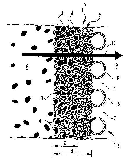
Fig. 1 is a cross-section of a portion of a filter cartridge on an enlarged
scale; and
Fig. 2 is a longitudinal cross-section of the filter cartridge of the
invention in the
form of a filter candle.
Fig. 1 shows, on an enlarged scale, a portion of a filter cartridge 1
consisting of a
porous layer 2 of polymeric material. This polymeric material is preferably a
polypropylene, of which the particles are sintered together or fused in such a
manner that the porous layer 2 is formed so as to contain pores 4. The porous
layer 2 is formed in such a manner that the pore size decreases in the
direction
of flow, as indicated by the arrow 10, ie from a non-filtrate side 8
progressively
toward a filtrate side 9. On the filtrate side 9 of the porous layer 2 there
is
disposed a supporting element 5 comprising ribs 6 with intermediate passages
7.
In some of the pores 4 formed within the porous layer 2, a filter aid 3 is
included
and retained, the introduction of said filter aid being effected from the non-
filtrate side 8. Since the size of the pores 4 decreases in the direction of
the
arrow 10 and the possibility of incorporation of filter aid is determined by
the
pore size, the depth of penetration E of the filter aid 3 in the porous layer
2 is
restricted. In the working example shown, the depth of penetration E is equal
to
approximately two-thirds of the thickness d of the porous layer 2.

CA 02480547 2004-09-24
WO 03/103800 PCT/EP03/05890
-5-
Fig. 2 shows a fiilter candle 11 substantially comprising a tubular body 12,
whose
structure corresponds to the porous layer 2 containing pores 4 with
incorporated
filter aid 3, as illustrated in Fig. 1. The filter candle 11 possesses a
candle base
13 to allow it to be mounted on a support plate or an appropriate terminator
or
the like, packing rings 14 being provided on the candle base 13. At the other
end
of the tubular body 12 comprising the filter candle 11 there is disposed a
terminating plate 15, which hermetically seals this end of the tubular body
12,
thus separating the non-filtrate side 8 from the filtrate side 9. In the
embodiment
shown in Fig. 2, the thickness d of the porous layer 2 or the wall thickness
of the
tubular body 12 is such that it is equal to approximately 0.23 times the
diameter
D of the tubular body 12. A particularly suitable range of the ratio of wall
thickness d to diameter D we regard as being from 1:3 to 1:5.
The filter cartridge described above affords, by reason of the particles of
filter
accelerator retained (and optionally additionally fixed or anchored) in the
porous
layer (deep-bed filtration layer), the possibility of carrying out precoat
filtration
without precoating. This leads to considerable saving of time and expense and
to
the completely novel possibility of carrying out two or even three filtering
actions
concurrently in a single filter.
The filter aid can be provided with the filter aid prior to the insertion of
the filter
cartridge into a filter housing, ie it can be supplied and installed as a
complete
unit. On the other hand, it is alternatively possible to install the unit
consisting of
the porous layer into a filter housing and to carry out the incorporation and
fixation of the filter aid and, optionally, stabilizer prior to the first
start-up or first
filtration operation. For this purpose, filter aid is fed by means of a
metering
pump via a closed-loop water circuit to the porous layer, in which it is
embedded
and anchored. Filtration can commence immediately after the filter housing has
been emptied. Further conditioning of the filter cartridge is not necessary.

Representative Drawing
A single figure which represents the drawing illustrating the invention.
Administrative Status

2024-08-01:As part of the Next Generation Patents (NGP) transition, the Canadian Patents Database (CPD) now contains a more detailed Event History, which replicates the Event Log of our new back-office solution.

Please note that "Inactive:" events refers to events no longer in use in our new back-office solution.

For a clearer understanding of the status of the application/patent presented on this page, the site Disclaimer , as well as the definitions for Patent , Event History , Maintenance Fee  and Payment History  should be consulted.

Event History

Description Date
Time Limit for Reversal Expired 2009-06-05
Application Not Reinstated by Deadline 2009-06-05
Inactive: Abandon-RFE+Late fee unpaid-Correspondence sent 2008-06-05
Deemed Abandoned - Failure to Respond to Maintenance Fee Notice 2008-06-05
Inactive: IPC from MCD 2006-03-12
Letter Sent 2005-03-08
Inactive: Single transfer 2005-02-04
Inactive: Courtesy letter - Evidence 2004-12-07
Inactive: Cover page published 2004-12-06
Inactive: Notice - National entry - No RFE 2004-12-01
Application Received - PCT 2004-10-28
National Entry Requirements Determined Compliant 2004-09-24
Application Published (Open to Public Inspection) 2003-12-18

Abandonment History

Abandonment Date Reason Reinstatement Date
2008-06-05

Maintenance Fee

The last payment was received on 2007-05-16

Note : If the full payment has not been received on or before the date indicated, a further fee may be required which may be one of the following

  • the reinstatement fee;
  • the late payment fee; or
  • additional fee to reverse deemed expiry.

Patent fees are adjusted on the 1st of January every year. The amounts above are the current amounts if received by December 31 of the current year.
Please refer to the CIPO Patent Fees web page to see all current fee amounts.

Fee History

Fee Type Anniversary Year Due Date Paid Date
MF (application, 2nd anniv.) - standard 02 2005-06-06 2004-09-24
Basic national fee - standard 2004-09-24
Registration of a document 2005-02-04
MF (application, 3rd anniv.) - standard 03 2006-06-05 2006-05-16
MF (application, 4th anniv.) - standard 04 2007-06-05 2007-05-16
Owners on Record

Note: Records showing the ownership history in alphabetical order.

Current Owners on Record
PALL CORPORATION
Past Owners on Record
GEORG SCHNIEDER
NIKOLAJ SCHMID
RALF ASCHER
Past Owners that do not appear in the "Owners on Record" listing will appear in other documentation within the application.
Documents

To view selected files, please enter reCAPTCHA code :


To view images, click a link in the Document Description column. To download the documents, select one or more checkboxes in the first column and then click the "Download Selected in PDF format (Zip Archive)" or the "Download Selected as Single PDF" button.

List of published and non-published patent-specific documents on the CPD .

If you have any difficulty accessing content, you can call the Client Service Centre at 1-866-997-1936 or send them an e-mail at CIPO Client Service Centre.


Document
Description 
Date
(yyyy-mm-dd) 
Number of pages   Size of Image (KB) 
Representative drawing 2004-09-23 1 35
Description 2004-09-23 5 235
Drawings 2004-09-23 2 53
Claims 2004-09-23 3 84
Abstract 2004-09-23 2 73
Notice of National Entry 2004-11-30 1 193
Courtesy - Certificate of registration (related document(s)) 2005-03-07 1 105
Reminder - Request for Examination 2008-02-05 1 119
Courtesy - Abandonment Letter (Maintenance Fee) 2008-07-30 1 173
Courtesy - Abandonment Letter (Request for Examination) 2008-09-22 1 165
PCT 2004-09-23 3 80
Correspondence 2004-11-30 1 26