Note: Descriptions are shown in the official language in which they were submitted.
~ ' CA 02480710 2004-09-28
PCT/EP03/03053
Wireless Remote-Control System and
Method for Operating Said System
The invention relates to a radio ripple control system for the control of a
plurality of decentralized customer terminals in dependence on customer-
initiated transmission requests by means of central longwave transmis-
sion devices having the features of claim 1.
The invention also relates to a method for the operation of such a radio
ripple control system having the features of claim 21.
The principle of the control of terminals by means of a longwave ripple
control system is generally known. A plurality of customers can utilize a
common longwave transmission device with this system in order to control
their own terminals or the terminals of their own customers. Energy sup-
ply corporations utilize the control system for tariff and load control and
for the control of lighting devices such as street lighting.
A control and message transmission system is known from WO
91 / 13523as well as a corresponding method which has a plurality of
transmitters which are not longwave transmitters. A central control unit,
for example in the form of a PC, is provided which is connected to a cen-
tral computer of a power plant and which communicates with a public
personal paging system which addresses the respectively desired transmit-
ter in order to transmit specific messages to groups of consumers. In a
CA 02480710 2004-09-28
2
modified embodiment, the central control unit is connected to an RDS
coding block which communicates with a plurality of computers for which
specific data can be input into the RDS coding block. The central unit, on
the one hand, receives that information which forms the basis for the
communications to be transmitted and, on the other hand, transmits the
control signal for the transmitters.
WO 02/09467 A1 relates to a system for the remote querying of the energy
amounts used by consumers, with data transmission devices being used
being able to be brought into communication with the Internet.
It is the object of the invention to provide a radio ripple control system as
well as a method for the operation of such a system whereby a plurality of
users, who make different demands on a radio ripple control system, are
allowed to control any desired number of their own terminals either singly
or group-wise in accordance with individual wishes, with the radio ripple
control system in particular being able to be expanded in a simple manner
to any desired number of users with in each case any desired number of
terminals to be controlled and generally being open to everyone irrespec-
five of their place of residence or work and irrespective of the locations of
the terminals to be controlled.
This object is satisfied by the features of claim 1 relating to the radio
ripple control system.
In accordance with the invention, a decentralization is also advanta-
geously provided of the central devices important for the operation of the
radio ripple control system by the provision of at least two longwave
~
. CA 02480710 2004-09-28
3
transmitters with each of which a central unit is associated for the control
of the transmission operation.
A particularly flexible organization of the radio ripple control system is
hereby made possible. The individual customers or the radio receivers
associated with their terminals to be controlled can be directly associated
with the individual central units in accordance with an individually pre-
determinable organizational scheme. In particular, those radio receivers
stationed in the overlapping region of the ranges of a plurality of longwave
transmitters can be alternatively associated with one of the longwave
transmitters.
The radio receivers are preferably only designed for the reception of one
single longwave frequency.
In accordance with a particularly preferred embodiment of the invention,
the radio ripple control system is designed such that the communication
connections between at least some of the customer stations and the cen-
tral units can be set up via the Internet.
By the inclusion of the Internet, the radio ripple control system is advan-
tageously opened up to everyone. It is in particular made possible hereby
for private households to be able to utilize the radio ripple control system
with minimum investment costs and at affordable utilization costs in
order, for example, to control their own domestic technical equipment.
Provision is furthermore preferably made in accordance with the invention
for the communication connections between at least some of the customer
~
. . , CA 02480710 2004-09-28
4
stations and the central units to be able to be set up via an existing tele-
communications network.
Not only telephone landlines can be used for the setting up of the commu-
nication connections, but also in particular mobile radiotelephone net-
works.
A user can thereby, for example with the aid of his laptop, switch the
heating of his house on or off or activate, deactivate or reprogram an
automatic lighting system serving as a break-in protection during his
absence from basically any location.
Generally any available communication connection can be used for the
communication between the customer stations and the central units.
Provision can thus be made for at least some of the communication con-
nections to be able to be set up between the customer stations and the
central units while utilizing the networks or protocols Datex-P, ISDN,
DSL, UMTS, GSM, GPRS, EDGE, 3GSM, X.25, X.75, IP and/or TCP.
The hardware required at the customer side for the communication with
the central units is hereby limited to the minimum anyway present in
practically every household today.
A particularly high degree of flexibility is achieved when, in accordance
with a further preferred embodiment of the invention, a number, and in
particular a plurality, of customer terminals can be controlled simultane-
ously, alternatively either individually or group-wise, with one transmis-
sion request.
CA 02480710 2004-09-28
The central units are preferably each arranged in spatial proximity to their
respective longwave transmitters. One central unit and the associated
longwave transmitter jointly form one of the central longwave transmis-
sion devices, with the number of such longwave transmission devices
5 generally being able to be any desired one in total within the radio ripple
control system in accordance with the invention.
Provision is furthermore preferably made for at least one central monitor-
ing unit to be provided with which communication connections can be set
up with all central units. The monitoring unit is preferably spatially sepa-
rate from the central units and the longwave transmitters.
The system can be monitored and serviced by means of the monitoring
unit. It is furthermore possible to provide the monitoring unit for such
processes as e.g. new customer registrations or changes to customer data
which cannot or should not be made automatically by the central units
alone. With respect to the customer stations, the monitoring unit is pref-
erably in particular characterized by further reaching system authoriza-
tions.
As with one of the customer stations, a communication connection to any
of the central stations can be established and e.g. the system status of the
transmission device in question be checked from the monitoring unit.
Irrespective of the number of longwave transmitters and central units, it
can be sufficient for precisely one central control unit to be provided, with
it, however, also being possible for a plurality of such monitoring units to
be present - e.g. one at each important location of the system operator.
The or each control unit can also be mobile in the sense that e.g. a laptop
CA 02480710 2004-09-28
6
having corresponding monitoring software serves as the central monitor-
ing unit.
In accordance with a further preferred embodiment of the invention, the
transmission requests each include a pre-determinable transmission
priority and/or a requested transmission time.
The customers can hereby determine themselves at which times specific
control processes or switch processes should take place at their terminals.
Provision can furthermore be made for the customers to fix the priorities
of their transmission requests themselves, with different utilization
charges being able to be incurred for different priorities. The customer can
thus decide himself how much a prompt transmission or a transmission
in exact accordance with the time request of the radio control telegrams
initiated by him is worth.
Provision can alternatively or additionally be made for the transmission
priority to be fixedly pre-set for every customer and for it not to be able to
be changed by the customer. Private customers can e.g. thus generally be
granted a lower priority than large customers such as energy supply
corporations or municipal utility companies.
This prioritization of the transmission requests, which can generally take
place independently of the actual technical performance capability of the
radio ripple control system, advantageously provides the possibility of a
direct grading, and in particular of a problem-free variable grading, of
utilization charges.
CA 02480710 2004-09-28
7
In the radio ripple control system in accordance with the invention, provi-
sion can furthermore preferably be made for transmission requests which
are incoming at the central units and have a pre-determined transmission
priority to be able to be delayed in time.
Transmission requests can hereby also deliberately be delayed when the
system or the relevant transmission device is not working at full capacity
and the transmission request could also be carried out with immediate
effect directly after arrival at the relevant central unit. This is in
particular
of advantage in connection with a system of utilization charges graded by
different transmission priorities and makes a differentiated price policy
and a corresponding marketing possible in this manner.
Utilization possibilities with a particularly large variety for the customers
are provided if, in accordance with a further preferred embodiment of the
invention, a one-time or a periodic transmission of radio control telegrams
can optionally be initiated by means of the transmission requests. Pref
erably, In the case of a one-time transmission, an immediate transmission
or a transmission taking place at a pre-determinable point in time can
optionally be initiated.
The radio ripple control system in accordance with the invention is fur-
thermore designed in a preferred embodiment such that successive radio
ripple control telegrams of at least one longwave transmission device, and
preferably of every central longwave transmission device, can be transmit-
ted at a time interval of approximately 1 sec.
t CA 02480710 2004-09-28
A particularly high-power system is hereby made available with which a
large number of users or customers can also be served who are transmit-
ting transmission wishes more or less simultaneously.
The terminals to be controlled can generally be any desired technical
devices which can be switched on or off and/or can be programmed or
parameterized. They can be complex units for tariff and load control in the
sector of energy supply corporations or for the control of streetlights in the
responsibility of municipal utilities.
The terminals can, however, also be technically simple apparatuses such
as conventional socket boards via which electrical consumers present in
private households can be switched on and off.
Every terminal is associated with a radio receiver which is in a position to
receive the radio control telegrams transmitted by the longwave transmit-
ters, to decode the information contained in the radio control telegrams
and to convert this information or to transmit control signals to the termi-
nals such that the desired control and/or switch processes can be trig-
gered at the respective terminal.
The radio receivers can be integrated in the terminals. Alternatively, a
spatially separate arrangement of radio receiver and terminal is possible.
Furthermore, a plurality of terminals can be associated with one radio
receiver in order thus to make possible a group-wise control of terminals.
A group-wise control of terminals can alternatively also take place in that
a separate radio receiver is associated with each terminal and all radio
receivers are addressed simultaneously by corresponding radio control
telegrams.
't CA 02480710 2004-09-28
9
The selection of the required radio receivers preferably takes place by the
user at the customer station by inputting the corresponding radio receiver
addresses. A plurality of radio receivers can have the same address such
that the user only has to input a single address for the simultaneous
control of a plurality of radio receivers. This address is not checked by the
relevant central unit, but the transmission of the radio control telegram
containing the address takes place automatically - optionally after check-
ing the authorization of the respective customer - by the central unit and
by the respective longwave transmitter, whereby the plurality of radio
receivers are addressed simultaneously.
The terminals can in particular be units freely available for the user com-
mercially or through the operator of the radio ripple control system which
can be purchased at prices also acceptable for private persons.
In a preferred embodiment of the invention, switch units with switching
functions are provided as the controllable customer terminals, with the
switch units preferably being able to be switched on and off by means of
the radio control telegrams.
These are therefore such terminals which need a received radio control
telegram at their radio receiver for a switching process.
The terminals do not have to be purely switch units to which one or more
units ca.n be connected, but technical domestic devices such as the house
lighting, electric shutters, saunas or heating equipment can also be di-
rectly controlled via the radio receivers.
CA 02480710 2004-09-28
Furthermore, the control processes at the terminals which can be initiated
by means of the transmission requests do not have to be pure switching
processes. It is also possible to reprogram units remotely using the radio
ripple control system in accordance with the invention which, for example,
5 operate automatically and independently according to their own time
switching scheme specific to the terminal, e.g. time switches for the house
lighting, by transmission of a customer-initiated radio control telegram
Furthermore, lighting devices can be provided as controllable customer
10 terminals such as streetlights, shop lighting, shop window lighting and
advertising lights. Such applications are in particular interesting for
commercial operators of food chains or drugstore chains.
Furthermore, equipment can also be controlled using the radio ripple
control system in accordance with the invention which is important for
the public community. For example, all siren equipment of a region or of a
country can~thus be activated by transmission of a single transmission
request.
In a further improved embodiment of the invention, provision is made that
equipment is provided as controllable customer terminals for the display
or presentation, in particular the optical display or presentation, of infor-
mation transmitted by means of the radio control telegrams
Such terminals can e.g. be price display devices in supermarkets. The
supermarket operators can use the invention in the case of price changes
simply to remark the products in question by initiating a corresponding
transmission request. A further example for the transmission of informa-
'~~ CA 02480710 2004-09-28
11
tion by means of the invention are the current waiting periods at stops of
local public transport.
The possibility in accordance with the invention of transmitting display-
s able or presentable information optionally to basically any desired number
of terminals or directly to a specific terminal with the aid of longwaves
generally opens up a wide field of applications previously not realizable for
a wide spectrum of customers.
A particular advantage of the radio ripple control system in accordance
with the invention, above all for private users, is the use of longwaves for
the control signal transmission, since there can practically be no recep-
tion difficulties for any installation location of the radio receivers due to
their penetration capability. The radio receivers can thus be arranged
without problem e.g. in cellar spaces and thus - for example, for the
control of a heating plant or of a central control plant for a plurality of
domestic technical devices - in direct proximity to the terminal to be
controlled in each case.
In this respect, the radio control system in accordance with the invention
based on longwaves provides substantial advantages with respect to the
mobile radio technology which works with substantially shorter wave
electromagnetic radiation.
A particularly simple and comparatively cost-favorable possibility for the
transmission of transmission requests to the central units is provided in
that, in accordance with a further preferred embodiment of the invention,
PCs and/or laptops with software for the input and transmission of
transmission requests are provided as customer stations.
'y CA 02480710 2004-09-28
12
The object underlying the invention is moreover satisfied by the features
of the independent method claim 21.
A particularly simple and customer-friendly operation of the radio control
system in accordance with the invention results, in accordance with a
particularly preferred embodiment, when the customer terminals to be
controlled are selected at the customer stations and a communication
connection is in each case set up automatically to the central unit associ-
ated with the radio receiver in dependence on the location of the respec-
tive radio receiver.
The customer consequently does not have to make any considerations as
to which of the central units his terminal to be controlled is associated
with in each case.
For this purpose, a radio receiver address is preferably associated with
each radio receiver and is stored in the system so that by the selection of
a radio receiver at a customer station it is automatically recognized with
reference to the address to which central unit a communication connec-
tion has to be set up so that this central unit can control the longwave
transmitter associated with it, via which the respective radio receiver can
be reached, for the transmission of the radio control telegram correspond-
ing to the transmission request.
CA 02480710 2004-09-28
13
tion has to be set up so that this central unit can control the longwave
transmitter associated with it, via which the respective radio receiver can
be reached, for the transmission of the radio control telegram correspond-
ing to the transmission request.
Provision is furthermore preferably made in accordance with the invention
for communication connections to be set up automatically to all central
units associated with the respective radio receivers for transmission re-
quests relating simultaneously to a plurality of customer terminals.
The user hereby also does not have to make any considerations of with
how many and with which central units he must communicate so that his
transmission request is carried out properly in cases in which the radio
receivers belonging to his transmission request cannot be reached or -
due to a permanent or temporary system operating state desired by the
system operator - should not be reached by one single longwave transmit-
ter alone.
In accordance with a further embodiment of the invention, provision is
made for at least two longwave transmitters, in particular located at the
same location, to be associated with at least one central unit and for radio
control telegrams to be transmitted by them at different longwave fre-
quencies simultaneously or offset in time in dependence on the transmis-
sion requests, with the transmission regions of the longwave transmitters
preferably being substantially identical or overlapping one another at least
to a large extent.
If one longwave transmitter and one longwave frequency used by this are
termed a radio cell, then the possibility is provided by this embodiment of
CA 02480710 2004-09-28
14
the invention to work with a plurality of radio cells for the customer-
initiated control of customer terminals. Such longwave radio cells cannot
be compared with a spatially closely restricted mobile radio cell since, in
the radio ripple control system in accordance with the invention, all radio
cells of a transmission device including a plurality of longwave receivers
can cover the same transmission territory when the transmission territo-
ries of the longwave transmitters overlap one another 100%.
By the simultaneous or time-offset utilization of a plurality of such radio
cells, a further differentiation possibility is advantageously provided and
the flexibility and the capability of the system to react to the most varied
customer requests is further increased.
If is furthermore possible in accordance with a further embodiment of the
invention for radio control telegrams which agree in content to be trans-
mitted at different longwave frequencies simultaneously or offset in time
in dependence on the transmission requests.
The radio cells admittedly differ here with respect to the longwave fre-
quencies used and/or to the longwave transmitters used for the transmis
sion, but not with respect to the information transmitted to the radio
receivers for the control of the terminals.
In accordance with a particularly preferred embodiment of the invention,
a differentiation is made in the operation of the radio ripple control system
between individual customers and large customers, with at least one
system-inherent portal, in particular an Internet server, being made
available to the individual customers and communication lines being
CA 02480710 2004-09-28
made available to large customers for customer portals of their own, in
particular for customer servers of their own.
The possibility hereby exists for large customers to offer radio ripple con-
s trot services themselves and, more or less, to locate themselves on top of
the radio ripple control system in accordance with the invention made
available by the actual system operator such that the actual system op-
eration is not recognizable for the end customer.
10 A particularly high reliability and precision of the radio ripple control
in
accordance with the invention is achieved when, in accordance with a
preferred embodiment, the radio receivers are synchronized by means of
the longwave transmitters in pre-settable time intervals with respect to a
pre-determined time standard.
The reliability and thus the acceptance by the customer can be further
increased if, in accordance with a particularly preferred embodiment, the
transmitted radio control telegrams are checked as to their correct trans-
mission and if a radio control telegram identified either as not transmitted
at all or as transmitted incorrectly, is transmitted again at least once.
For this purpose, a monitoring radio receiver can be provided, for example
at the location of each longwave transmitter, and can be connected to the
respective central unit with whose aid the actually transmitted actual
telegrams are compared with the desired telegrams corresponding to the
customer requests.
Further embodiments of both the radio ripple control system in accor-
dance with the invention and of the method in accordance with the inven-
,~ ~~' CA 02480710 2004-09-28
16
tion for the operation of such a system are recited in the dependent claims
in the description and in the drawing.
The invention will be described in the following by way of example with
reference to the drawing whose single figure illustrates, purely schemati-
cally, the design and the functionality of a radio ripple control system in
accordance with the invention.
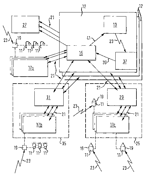
The schematically represented radio ripple control system in accordance
with the invention includes three longwave transmission devices 12 which
each include a longwave transmitter 13, a central unit in the form of a
redundant parallel computer system 15 as well as a monitoring radio
receiver 37. The number of such transmission devices 12 is generally any
desired in accordance with the invention and depends on the size of the
transmission region to be covered. The frequencies used by the longwave
transmitters 13 are preferably different from one another to avoid interfer-
ence, in particular in overlapping areas of the transmission regions.
The stationing of the longwave transmitters 13 preferably takes place
such that a reliable reception is possible at every point of the transmis-
sion territory to be covered, with range overlappings being as small as
possible. To cover Germany, two longwave transmitters are, for example,
sufficient which work in a frequency range from 70 to 150 kHz and which
each have a range of several 100 kilometers around the transmitter loca-
tion.
The transmission of the information corresponding to a specific transmis-
sion request to radio receivers 19 arranged decentrally in the reception
region takes place by digital frequency modulation, digital amplitude
CA 02480710 2004-09-28
v,
17
modulation or other modulation methods of the longwave signal also
termed a radio control telegram 23 and indicated in each case in the
Figure as a jagged arrow.
The radio receivers 19 each have a decoder unit with which the informa-
tion contained in the received longwave signal can be read. This informa-
tion can only be utilized by those radio receivers 19 whose addresses are
contained in the respective radio control telegram 23.
A plurality of radio receivers 19 can have the same address in order only
to have to input a single radio receiver address on the initiating of a
transmission request for the simultaneous control of these radio receivers
19.
The design and functionality of the central computers 15 and the purpose
of the monitoring receiver 27 are described in more detail at a different
point.
The radio ripple control system in accordance with the invention further-
more includes a plurality of decentralized or offset customer stations 17a,
17b, 17c. In the embodiment shown, a difference is made between differ-
ent types of customer stations 17a, 17b, 17c, with the differences being
due to the manner of the link to the central computers 15, to the proper-
ties and/or demands of the customers who utilize the stations 17a, 17b,
17c and to the motivation on the basis of which the customers respec-
tively utilize the stations 17a, 17b, 17c and thus the ripple control in
accordance with the invention. This will also be considered in more detail
in the following.
' CA 02480710 2004-09-28
,
18
The radio receivers 19 are each shown in the proximity to the relevant
customer stations 17a, 17b, 17c in the Figure for the illustration of the
organization of the radio ripple control system in accordance with the
invention. It is made clear in the Figure by the jagged arrows directed
toward the respective radio receivers 19 and representing the radio con-
trol telegrams 23 that the radio control telegrams 23 transmitted by the
longwave transmitters 13 can be received by all the radio receivers 19
disposed in the respective transmission territory, provided that the radio
control telegrams 23 contain the corresponding radio receiver address.
The radio ripple control system furthermore includes a single monitoring
unit 27 which can communicate with each of the central computers 15.
The customer stations 17a, 17b, 17c and the control unit 27 are provided
in the form of PCs or laptops and can agree in large parts with respect to
the software running for the utilization of the ripple control system, with,
however, a system monitoring, care and management being possible via
the monitoring unit 27 which is closed to the customers using the normal
customer stations 17a, 17b, 17c.
All functions which the customers can use from the customer stations
17a, 17b, 17c are preferably automatically taken over only by the central
computers 15, i.e. the central monitoring station 27 is not required for the
normal customer operation. In particular no communication connections
are required for the normal operation between the customer stations 17a,
17b, 17c, on the one hand, and the monitoring station 27, on the other
hand.
CA 02480710 2004-09-28
19
The communication connections 21 between the customer stations 17a,
17b, 17c and the monitoring unit 27, on the one hand, and the central
computer 17, on the other hand, are indicated by double arrows in the
Figure. With the exception of the customer stations 17a shown at the top
left in the Figure, a communication connection 21 can be set up at every
customer station 17b, 17c to each of the central units 15.
With the mentioned customer stations 17a communicating only with one
of the central computers 15, it is not required or it is not wanted for sys-
tem organizational reasons that communication also takes place with the
other central units 15 and the representation of these customer stations
17a in the Figure should also illustrate the flexibility and the great variety
of the ripple control system in accordance with the invention. These cus-
tourer stations 17a communicating only with one central computer 15
can, for example, be fully functional old units whose conversion is not
required or is not wanted. The communication between these customer
stations 17a and the respective central computer 15 takes place via the
Datex-P network (X.25).
In the customer stations 17c shown at the bottom right in the Figure, the
set-up of the communication connections 21 to the individual central
computers 15 takes place in each case while using the Internet 25. A
system-inherent portal is made available for a customer circle, in particu-
lar formed by private customers, in the form of an Internet server 29 with
which the customers can dial in via the normal landline telephone or a
mobile radio network by means of their own PCs or laptops serving as a
customer station 17c. The customers consequently only need an "Internet
capable" computer 17c, but not any special software which only serves for
' CA 02480710 2004-09-28
the utilization of the radio ripple control system in accordance with the
invention.
For anther customer circle formed in particular by large customers who in
5 turn serve their own end customers and shown at the bottom left in the
Figure, there is the possibility of being able to communicate with the
central computers 15 of the radio ripple control system in accordance with
the information via a portal 31 dedicated to big customers - in particular
in the form of a server dedicated to big customers with which the end
10 customers can in turn dial in via their own PCs or laptops 17b while using
a normal telecommunications network 21 and/or a big customer network
35 operated or made available by the big customers themselves.
The actual operator of the ripple control system does not confront the end
15 customer directly as the system operator, but the ripple control system is
used by the big customers to themselves offer radio ripple control services
for end customers.
The radio ripple control system in accordance with the invention is used
20 by the customers to control their own terminals 11 in that, for example,
processes for switching on or off are triggered or programming sessions or
parameterization sessions can be carried out at the terminals 11.
A respective radio receiver 19 is associated either with each terminal 11 or
with a group of terminals 11 and it receives radio control telegrams 23
transmitted by the longwave transmitters 13 and triggers the control
processes on the basis of the information contained in these telegrams,
whereby the transmission requests are carried out which were previously
;' CA 02480710 2004-09-28
21
communicated to the central computers 15 via the customer stations 17a,
17b, 17c at the initiative of the customers.
Municipal utilities can thus, for example, switch streetlights on or off
simply street-by-street, as is shown schematically at the top left in the
Figure.
Commercial customers such as operators of store chains can automati-
cally switch lighting devices on or off e.g. to illuminate shop windows
simultaneously in all of their stores by means of the radio ripple control in
accordance with the invention, as is indicated at the bottom left in the
Figure.
The radio ripple control system in accordance with the invention provides
private customers with the possibility of e.g. controlling domestic techni-
cal equipment 11 while utilizing the Internet 25, as is indicated at the
bottom right in the Figure. For this purpose, it can be sufficient only to
install a radio receiver 19 and to connect the terminals) 11 to be con-
trolled to this radio receiver 19. Alternatively, a separate radio receiver 19
can be provided for each terminal 11 in the house.
The user can select all radio receivers 19 or individual radio receivers 19
directly with his PC or laptop 17c and transmit corresponding transmis-
sion requests to the respective central computer 15 via the Internet server
29 forming the system portal. It is not important whether the user is in
the house or at another location, since the central computers 15 can be
contacted from any desired location by the use of the Internet 25.
'' CA 02480710 2004-09-28
22
The design and operation of the radio ripple control system in accordance
with the invention can take place, for example such as is described in the
following.
The central units 15 are in each case a redundant computer system with
a main computer and a parallel computer. Each of the two computers
includes a physically independent functional unit having four main func-
tions which are designated as a bus system, a control computer, a moni-
toring computer and a charge calculator, since the central computer 15
combines all these functions in it.
The bus system, or the corresponding functional section of the central
computer 15, serves for the switching of the logical communication chan-
nels 21 between the offset customer stations 17a, 17b, 17c and the indi-
vidual functional sections of the central computer 15 and between the
individual functional sections of the central computer 15 among one
another. Furthermore, the respectively current parameter record of the
central computer 15 is guided by the bus system. The bus system func-
tion furthermore takes over control and monitoring functions for the
central computer 15, detects inadmissible demand attempts and keeps a
local operations diary.
The control computer, or the corresponding functional section of the
central computer 15 provides the control of the respective longwave
transmitter 13. The acceptance of the customer data packets, i.e. of the
transmission requests with which the radio receiver 19 should be con-
trolled or programmed, the transmission of the corresponding control
commands 41 to the longwave transmitters 13 for the transmission of the
radio control telegrams 23, the acceptance of parameterization instruc-
'' CA 02480710 2004-09-28
23
tions of the bus system function and the feedback of the system status,
the detection of operating data and the keeping of a local operational diary
take place by means of the control computer system.
The transmission operation is monitored by the monitoring computer, or
by the corresponding functional section of the central computer 15, with
the actual transmission operation being able to be reconstructed at a later
point in time on the basis of the operating data detected by the monitoring
computer function.
In particular the desired/actual comparison of the transmitted radio
control telegrams 23, the monitoring of the operation status of the long-
wave transmitter 13, the detection of data relating to the actual transmis-
sion operation, the acceptance of parameterization instructions of the bus
system function and the keeping of a local operations diary take place
with the aid of the monitoring computer function.
The charge computer, or the corresponding functional section of the cen-
tral computer 15, serves to monitor the transmission demands originating
from the customer stations 17 and from the system's own central monitor-
ing unit 27. In particular the billing data required for a correct billing are
recorded. Furthermore, the charge computer function accepts parameteri-
zation instructions of the bus system function and keeps a local opera-
tions diary.
The central computers 15 of the radio ripple control system in accordance
with the invention are in particular characterized by the use of a multi-
tasking operating system with real time capability, whereby a particularly
high time precision can be achieved on the transmission of the radio
CA 02480710 2004-09-28
24
control telegram 23. Furthermore, every central computer 15 has an
addressing volume of, for example, 64,000 single addresses, with the
addressing volume generally being able to have any desired size in de-
pendence on the number of the radio receivers 19 stationed in the recep-
tion region.
The customer stations 17a, 17b, 17c, or the software installed on the
customer stations and/or on the central units, are designed such that the
transmission of the radio control telegrams 23 takes place by means of a
time list, with the radio control telegram database being scaleable. The
customer stations 17a, 17b, 17c furthermore make a wide customer
administration possible, monitor the system statuses, provide for a proto-
coiling, have a web server functionality, serve as a communication inter-
face to network guide systems and in particular allow a process coupling
to analog or digital transducers via a correspondingly designed IO inter-
face.
The light conditions prevailing at the location of the lighting devices to be
controlled - e.g. streetlights - can be detected by the transducers and
transmitted to the respective customer station 17a, 17b, 17c at which a
transmission request to switch the lighting devices on or off is automati-
cally transmitted to the relative central computers) on the reaching of
pre-determined threshold values.
Different access authorizations are distinguished with respect to the use
or operation of the radio ripple control system in accordance with the
invention. The customers of the system have access via the customer
stations 17a, 17b, 17c to the query of the system status and to the trans-
mission of transmission requests and thus to the programming of radio
' ,~ CA 02480710 2004-09-28
radio control telegrams. However, this only applies with respect to those
application addresses which are released for the respective customer, with
the release of the application addresses being reserved to the system
operator.
5
The system operator or its system administrators have free access to all
functions of the ripple control system, i.e. to the querying of the system
status, to the programming of radio control telegrams 23 for all existing
application addresses and to the actual administration, including the
10 customer administration, via the central monitoring unit 27.
~rthermore, a service authorization is defined which only has access to
the query of the system status. This service serves in particular for the
alarm giving in the case of a malfunction occurring in the system.
The following safety precautions exist for the monitoring of the individual
access authorizations by the system; on an access of the system via
Datex-P (X.25), only the Datex-P address is required for a clear identifica-
tion of the customer. The individual Datex-P addresses of the customers
are administered by the system operator, with the Datex-P address of the
system operator itself being able to be changed - and this is the preferred
procedure - via the central monitoring unit 27 or by an on-site operation,
i.e. at the location of the respective central computer 15.
The access authorization to all other communication connections 21 is
ensured by a "LOGIN" and by the encoding of the communication (e.g. 128
bits), with the names, passwords and authorizations of the customers
being stored in the central computers 15 and being able to be adminis-
tered when required via the system's own monitoring unit 27.
,;' CA 02480710 2004-09-28
26
On communication between the customer stations 17a, 17b, 17c and the
control unit 27, on the one hand, and the central computers 15, on the
other hand, the respective demands arriving at the central computers 15
are checked according to certain criteria and optionally rejected. In addi-
tion to the formal correctness, the demands must contain pre-determined
authorizations and restrictions.
Demands which do not have the required authorization or which infringe
the currently valid restrictions, are rejected with a corresponding error
message. The central computer 15 keeps a protocol of inadmissible de-
mand attempts.
Within the framework of the warranties given by the system operator to
the customers, the central computers 15 must each be in a position to
serve a plurality of customers, and thus a plurality of logical communica-
tion channels or communication connections 21 practically simultane-
ously. The "most critical" case is given for a central computer 15 when a
plurality of, for example, 30 customers simultaneously transmit a trans-
mission request of the highest priority and for the immediate, one-time
transmission of a radio control telegram 23.
The central computers 15 are each designed such that such transmission
requests are admittedly constantly accepted by the customer stations 17a,
17b, 17c, but are treated in accordance with a specific priority order. This
priority order consists of transmission requests for the immediate, one-
time transmission of a control telegram having a higher priority than all
other transmission requests, with the treatment priority within these
generally highest priority transmission requests being oriented on the
CA 02480710 2004-09-28
27
respective transmission priorities contained in the individual transmission
requests.
In connection with the programming of radio control telegrams 23 or the
acceptance of the transmission wishes, the central computers 15 each
take over the individual tasks named in the following. The memory loca-
tions provided for the individual transmission wishes are organized and
administered. Furthermore, a monitoring takes place with respect to the
admissibility of the transmission wishes, with feedback taking place to the
respective customer station 17a, 17b, 17c both with respect to successful
and rejected transmission requests.
The customer can choose from among different classes of transmission
requests. Radio control telegrams 23 can thus be transmitted either (i)
immediately and once; (ii) once and at a certain time; (iii) periodically
monthly; (iv) periodically weekly; (v) periodically daily; or (vi)
periodically
hourly. Furthermore, (vii) an additional function is available which con-
sists of, for example, transmitting an additional control telegram periodi-
cally, e.g. very 15 min., for test purposes. This additional function can be
reserved to the system operator and can in this case only be selected via
the system's own monitoring unit 27.
The memory location administration in the central computers 15 takes
the specialties inherent in the individual transmission request classes into
account. For example, a memory location for an immediate, one-time
transmission only remains "busy" for a very short period of time. Memory
locations for transmission requests with which the one-time transmission
of a radio control telegram is requested at a specific time in each case
' CA 02480710 2004-09-28
28
become "free" again, when the respective point in time contained in the
transmission request has been reached.
During operation, the central computers 15 each continuously monitor
the transmission requests or demands for radio control telegrams 23
stored in the memory locations, with only the memory locations having
the status "busy" being of interest. A transmission request or a demand
becomes due when the date and time of the central computer 15 agree
with the data describing the due time stored in the memory location.
Transmission wishes which have become due are transmitted in accor-
dance with their priority into one of the provide priority buffers, with the
priority buffers being of the FIFO buffer type.
Provision is made with respect to the control of the respective longwave
transmitter 13 or of the interface to the longwave transmitter 13 for a new
radio control telegram 23 to be made available by the central computer 15
for the transmission, i.e. the corresponding control commands 41 are
transmitted to the longwave transmitter 13 as soon as a radio control
telegram 23 has been transmitted. The waiting transmission request
having the highest priority is removed from the priority buffers in each
case and converted into control commands 41. The control commands 41
corresponding to the radio control telegram 23 to be transmitted are
transmitted to the longwave transmitter 13 via an RS232 interface.
To synchronize the radio receivers 19 stationed in the reception region,
the longwave transmitters 13 are caused by their central computers 15 to
transmit so-called time telegrams at pre-defined time intervals.
CA 02480710 2004-09-28
29
As already mentioned in the introductory part of the description, the
transmission of radio control telegrams 23 can be delayed by an adjust-
able time in dependence on the priority of the respective transmission
requests. The length of the delay can be pre-determined in dependence on
the individual priorities and/or in a customer specific manner or a cus-
tomer class specific manner.
To ensure a high quality of the services provided by the system operator, a
desired/actual comparison of the transmitted radio control telegrams 23
is provided. This desired/actual comparison serves in particular to com-
pensate short-term malfunctions of the longwave transmitters 13 in that
incorrectly transmitted radio control telegrams 23 are automatically rec-
ognized as such, on the one hand, and are transmitted again, on the other
hand.
For this purpose, those control commands 41 ("desired") transmitted in
each case to the longwave transmitters 13 and corresponding to the un-
derlying transmission request and, with the aid of the monitoring radio
receiver 37, the radio control telegram 23 ("actual") actually transmitted
by the longwave transmitter 13 are detected by the central computers 15
in that a so-called actual telegram 39 is transmitted from the monitoring
radio receiver 37 to the central computer 15.
These two signals are compared with one another bit-wise by the central
computer 15. In the event of non-agreement, the control commands 41
corresponding to the desired radio control telegram 23 are again transmit-
ted to the longwave transmitters 13. The number of the repeats of the
same radio control telegrams 23 taking place as a maximum can generally
be pre-set as desired.
CA 02480710 2004-09-28
Reference number list
11 customer terminal
12 transmission device
5 13 longwave transmitter
15 central unit, central
computer
17a, 17b, 17c customer station
19 radio receiver
21 communication connection
10 23 radio control telegram
25 Internet
27 central monitoring unit
29 system's own portal
31 customer's own portal
15 35 customer network
37 monitoring radio receiver
39 actual telegram
41 control commands