Note: Descriptions are shown in the official language in which they were submitted.
CA 02480950 2004-09-30
WO 03/085764 PCT/US03/04275
APPARATUS AND METHOD FOR AUTOMATICALLY
STACKING FUEL CELL MATERIAL LAYERS
FIELD OF THE INVENTION
The present invention relates generally to automated stacking of relatively
thin porous and non-porous material layers and, more particularly, to
apparatuses
and methods for automatically stacking porous and non-porous layers of a fuel
cell during fuel cell assembly.
BACKGROUND OF THE INVENTION
Various apparatuses have been developed to stack layers of varying
materials when constructing a stack of such material layers. Conventional
stacking apparatuses typically employ suction cups or a vacuum to releasably
engage and transport layers of a given material during a stacking operation.
Although such conventional arrangements may be satisfactory in certain
applications, implementing known approaches for stacking relatively thin
materials
having varying porosity renders conventional arrangements unworkable.
Moreover, it is often desirable to automate, either partially or completely, a
number of processes of a stacking operation. Many conventional material
handling, transporting, and stacking apparatuses and methods are not well
suited
for a high degree of automation, particularly stacking processes which have
tight
positional tolerance requirements.
There is a need for improved material layer stacking apparatuses and
methodologies. There is a further need for such apparatuses and methodologies
that can safely and precisely position and stack material layers of varying
porosity
in an automated assembly environment, such as in an automated fuel cell
assembly plant. The present invention fulfills these and other needs.
1.
CA 02480950 2004-09-30
WO 03/085764 PCT/US03/04275
SUMMARY OF THE INVENTION
The present invention is directed to methods and apparatuses for
facilitating automated stacking of various material layers having varying
porosity.
In accordance with the present invention, the material layers subject to
automated
stacking typically include at least one substantially non-porous material
layer and
at least one substantially porous material layer. A method of stacking such
material layers according to an embodiment of the present invention involves
applying vacuum to a first porous material layer to stabilize the first porous
a
material layer relative to a support structure. One or both of the support
structure
and a non-porous material layer are moved to establish contact between the non-
porous material layer and the first porous material layer. The first porous
material
layer and the non-porous material layer define a sub-assembly. While applying
vacuum to the sub-assembly, one or both of the support structure and a second
material layer are moved to establish contact between the second material
layer
and the non-porous material layer. Vacuum applied to the sub-assembly
maintains positional stability of the first porous material layer and non-
porous
material layer relative to the support structure while the second material
layer is
moved into contact with the non-porous material layer. Vacuum is subsequently
removed to facilitate transporting of the material layer stack.
In accordance with one embodiment directed to automated fuel cell
assembly, a number of fuel cell layers of varying porosity are processed,
including
at least a first fluid transport layer (first FTL), a second fluid transport
layer
(second FTL), and a membrane. The first and second FTLs are substantially
porous and the membrane is substantially non-porous. The automated stacking
process involves applying vacuum to the first FTL to stabilize the first FTL
relative
to a support structure. One or both of the support structure and the membrane
are moved to establish contact between the membrane and the first FTL, the
first
FTL and the membrane defining a sub-assembly. While applying vacuum to the
sub-assembly, one or both of the support structure and the second FTL are
moved to establish contact between the second FTL and the membrane. The
application of vacuum to the sub-assembly maintains positional stability of
the first
FTL and membrane relative to the support structure while the second FTL is
2
CA 02480950 2004-09-30
WO 03/085764 PCT/US03/04275
moved into contact with the membrane. Vacuum is subsequently removed to
facilitate transport of the fuel cell stack for downstream processing.
According to another embodiment, automated stacking of fuel cell layers is
facilitated with use of a transportable fixture assembly comprising a first
fixture
and a second fixture. The first and second fixtures include at least one
substantially porous region, respectively. The automated stacking process
involves moving one or both of a first FTL and the first fixture to establish
contact
between the first FTL and the first fixture. One or both of the first fixture
and a
membrane are moved to establish contacfi between the membrane and the first
FTL. The first FTL in contact with the first fixture and the membrane defines
a
first sub-assembly. One or both of the second fixture and a second FTL are
moved to establish contact between the second fixture and the second FTL. The
second FTL in contact with the second fixture defines a second sub-assembly.
While respectively applying vacuum to the first and second fixtures, one or
both of
the first and second fixtures are moved to establish contact between the
second
FTL and the membrane. The application of vacuum to the first sub-assembly
maintains positional stability of the first FTL and membrane relative to the
first
fixture, and the application of vacuum to the second sub-assembly maintains
positional stability of the second FTL relative to the second fixture. Vacuum
is
subsequently removed from the first sub-assembly and the second sub-assembly
to allow for the transporfi of the fuel cell stack for downstream processing.
In accordance with yet another embodiment.of the present invention, an
automated process of sfiacking and bonding fuel cell layers involves moving a
second surface of a first FTL into contact with a first support of a bonding
press.
Vacuum is applied to the second surFace of the first FTL to stabilize the
first FTL
on the first support. The membrane is moved into contact with a first surFace
of
the first FTL, fihe first FTL and the membrane defining a first sub-assembly.
Vacuum is applied to the first sub-assembly to maintain positional stability
of the
first FTL and membrane relative to the first support. Vacuum is applied to a
first
surface of the second FTL to stabilize the second FTL on a second support of
the
bonding press. One or both of the first and second supports are moved to
establish contact between a first surface of the membrane and a second surface
3
CA 02480950 2004-09-30
WO 03/085764 PCT/US03/04275
of the second FTL. The first FTL, membrane, and second FTL are bonded
together to produce a bonded fuel cell assembly. The automated stacking and
bonding processes may be employed to stack and bond material layers of varying
types and porosity.
The above summary of the present invention is not intended to describe
each embodiment or every implementation of the present invention. Advantages
and attainments, together with a more complete understanding of the invention,
will become apparent and appreciated by referring to the following detailed
description and claims taken in conjunction with the accompanying drawings.
BRIEF DESCRIPTION OF THE DRAWINGS
Figure 1 is an illustration of a fuel cell and its constituenfi layers;
Figures 2-4 illustrate features of a two-part fixture assembly well suited for
facilitating automated stacking of fuel cell layers in accordance with an
embodiment of the present invention;
Figures 5-11 illustrate various processes of an automated material layer
stacking operation in accordance with an embodiment of the present invention;
Figure 12 is a depiction of a processor controlled transport mechanism that
facilitates automated stacking of material layers in accordance with an
embodiment of the present invention;
Figures 13 and 14 illustrate embodiments of a bonding press adapted for
automated stacking and bonding of material layers in accordance with an
embodiment of the present invention; and
Figures 15-17 illustrate an embodiment of an automated fuel cell assembly
apparatus for fabricating fuel cells in accordance with the principles of the
present
invention.
While the invention is amenable to various modifications and alternative
forms, specifics thereof have been shown by way of example in the drawings and
will be described in detail. It is to be understood, however, that the
intention is not
to limit the invention to the particular embodiments described. On the
contrary,
the intention is to cover all modifications, equivalents, and alternatives
falling
within the scope of the invention as defined by the appended claims.
4
CA 02480950 2004-09-30
WO 03/085764 PCT/US03/04275
DETAILED DESCRIPTION OF VARIOUS EMBODIMENTS
In the following description of the illustrated embodiments, reference is
made to the accompanying drawings which form a part hereof, and in which is
shown by way of illustration, various embodiments in which the invention may
be
practiced. It is to be understood that the embodiments may be utilized and
structural changes may be made without departing from the scope of the present
invention.
A stacking method and apparatus of the present invention advantageously
provide for safe and precise handling of relatively thin material layers
during a
stacking operation, such as a picking and placing operation for example. A
method and apparatus according to the principles of the present invention are
particularly well suited for picking and placing porous and non-porous
material
layers to produce a stack of such material layers. In addition to handling
materials of varying porosity, a stacking method and apparatus of the present
invention can be implemented to handle and stack thin material layers of
varying
brittleness. A high degree of accuracy is achievable during picking, placing,
and
stacking operations for applications which have tight locational tolerance
requirements for building stacks of thin material layers.
In accordance with one application, an apparatus and method of the
present invention can be implemented to facilitate automated stacking of
material
layers defining a fuel cell or a portion of a fuel cell. A fuel cell is an
electrochemical device that combines hydrogen fuel and oxygen from the air to
produce electricity, heat, and water. Fuel cells do not utilize combustion,
and as
such, fuel cells produce little if any hazardous effluents. Fuel cells convert
hydrogen fuel and oxygen directly into electricity, and can be operated at
much
higher efficiencies than internal combustion electric generators, for example.
A typical fuel cell is depicted in Fig. 1. The fuel cell 10 shown in Fig. 1
includes a first fluid transport layer 12 adjacent an anode 14. Adjacent the
anode
14 is an electrolyte membrane 16. A cathode 18 is situated adjacent the
electrolyte membrane 16, and a second fluid transport layer 19 is situated
adjacent the cathode 18. In operation, hydrogen fuel is introduced into the
anode
CA 02480950 2004-09-30
WO 03/085764 PCT/US03/04275
portion of the fuel cell 10, passing through the first fluid transport layer
12 and
over the anode 14, At the anode 14, the hydrogen fuel is separated into
hydrogen ions (H+) and electrons (e ).
The electrolyte membrane 16 permits only the hydrogen ions or protons to
pass through the electrolyte membrane 16 to the cathode portion of the fuel
cell
10. The electrons cannot pass through the electrolyte membrane 16 and,
instead, flow through an external electrical circuit in the form of electric
current.
This current can power an electric load 17, such as an electric motor, or be
directed to an energy storage device, such as a rechargeable battery.
Oxygen flows into the cathode side of the fuel cell 10 via the second fluid
transport layer 19. As the oxygen passes over the cathode 18, oxygen, protons,
and electrons combine to produce water and heat.
Individual fuel cells, such as that shown in Fig. 1, can be.combined with a
number of other fuel cells to form a fuel cell stack. The number of fuel cells
within
the stack determines the total voltage of the stack, and the surFace area of
each
of the cells determines the total current. The total electrical power
generated by a
given fuel cell stack can be determined by multiplying the total stack voltage
by
total current.
An apparatus and method of the present invention can be implemented to
facilitate automated stacking of material layers in the construction of fuel
cells of
varying technologies. For example, the handling and stacking principles of the
present invention may be applied to construct proton exchange membrane (PEM)
fuel cells. PEM fuel cells operate at relatively low temperatures (about 175
degrees F), have high power density, can vary their output quickly to meet
shifts
in power demand, and are well suited for applications where quick startup is
required, such as in automobiles for example.
The proton exchange membrane used in a PEM fuel cell is a thin plastic
sheet that allows hydrogen ions to pass through it. The membrane is coated on
both sides with highly dispersed metal or metal alloy particles (e.g.,
platinum or
platinum/ruthenium) that are active catalysts. The electrolyte used is
typically a
solid organic polymer poly-perfluorosulfonic acid. Use of a solid electrolyte
is
advantageous because it reduces corrosion and management problems.
6
CA 02480950 2004-09-30
WO 03/085764 PCT/US03/04275
Hydrogen is fed to the anode side of the fuel cell where the catalyst
encourages the hydrogen ions to release electrons and become hydrogen ions
(protons). The electrons travel in the form of an electric current that can be
utilized before it returns to the cathode side of the fuel cell where oxygen
has
been introduced. At the same time, the protons diffuse through the membrane to
the cathode, where the hydrogen ions are recombined and reacted with oxygen to
produce water.
According to one PEM fuel cell construction, a PEM layer is sandwiched
between a pair of fluid transport layers, such as diffuse current collectors
or gas
diffusion layers for example. An anode is situated between a first FTL and the
membrane, and a cathode is situated between the membrane and a second FTL.
In one configuration, a PEM layer is fabricated to include an anode catalyst
coating on one surface and a cathode catalyst coating on the other surface.
According to another configuration, the first and second FTLs are fabricated
to
include an anode and cathode catalyst coating, respectively. In yet another
configuration, an anode catalyst coating can be disposed partially on the
first FTL
and partially on one surface of the PEM, and a cathode catalyst coating can be
disposed partially on the second FTL and partially on the other surface of the
PEM. The five layer construct defined by the first FTLlanode/PEM/cathode/
second FTL is referred to as a membrane electrode assembly (MEA).
The FTLs are typically fabricated from a carbon fiber paper or non-woven
material. Depending on the product construction, the FTLs can have carbon
particle coatings on one side. The FTLs, as discussed above, can be fabricated
to include or exclude a catalyst coating. The FTLs, according to this product
construction, are both porous and brittle. A material layer handling and
stacking
approach consistent with the principles of the present invention is
particularly well
suited for safely and accurately transporting and positioning thin, brittle
fuel cell
layers, such as FTLs for example.
Direct methanol fuel cells (DMFC) are similar to PEM cells in that they both
use a polymer membrane as the electrolyte. In a DMFC, however, the anode
catalyst itself draws the hydrogen from liquid methanol fuel, eliminating the
need
CA 02480950 2004-09-30
WO 03/085764 PCT/US03/04275
for a fuel reformer. DMFCs typically operate at a temperature between 120-190
degrees F.
Molten carbonate fuel cells (MCFC) use a liquid solution of lithium, sodium
and/or potassium carbonates, soaked in a matrix for an electrolyte. MCFCs
operate at about 1,200 degrees F. The high operating temperature is needed to
achieve sufficient conductivity of the electrolyte. Because of this high
temperature, noble metal catalysts are not required for the cell's
electrochemical
oxidation and reduction processes. MCFCs are typically operated on hydrogen,
carbon monoxide, natural gas, propane, landfill gas, marine diesel, and
simulated
coal gasification products.
A solid oxide fuel cell (SOFC) typically employs a hard ceramic material of
solid zirconium oxide and a small amount of ytrria, instead of a liquid
electrolyte,
allowing operating temperatures to reach 1,800 degrees F.
In regenerative fuel cells, water is separated into hydrogen and oxygen by
a solar-powered electrolyser. The hydrogen and oxygen are fed into the
regenerative fuel cell which generates electricity, heat, and water. The water
is
then recirculated back to the solar-powered electrolyser and the process is
repeated.
A protonic ceramic fuel cell (PCFC) employs a ceramic electrolyte material
that exhibits high protonic conductivity at elevated temperatures. PCFCs
operate
at about 1,300 degrees F. PCFCs can operate at high temperatures and
electrochemically oxidize fossil fuels directly to the anode. Gaseous
molecules of
the hydrocarbon fuel are absorbed on the surface of the anode in the presence
of
water vapor, and hydrogen ions are efficiently stripped off to be absorbed
into the
electrolyte, with carbon dioxide as the primary reaction product. These and
other
fuel cell technologies can be constructed and sfiacked by use of a handling
and
stacking apparatus and methodology in accordance with the present invention.
In the figures, there is illustrated apparatuses for automatically stacking a
number of relatively thin material layers, such as material layers of a fuel
cell. It is
often necessary or desirable to handle and transport various types of porous
and
non-porous material layers using the same apparatus when automatically
constructing stacks of such material layers. In the construction of a PEM fuel
cell,
s
CA 02480950 2004-09-30
WO 03/085764 PCT/US03/04275
for example, a non-porous PEM layer is sandwiched between a pair of porous
FTLs. Although it would appear that conventional vacuum techniques could be
employed to automate construction of the FTL/PEM/FTL stack, those skilled in
the art will readily appreciate that the non-porous nature of the sandwiched
PEM
layer renders such conventional techniques unworkable or impractical.
By way of example, assuming that a FTL/PEM/FTL stack has been
constructed, it is typically necessary to move this stack from the stacking
station
to one or more other process stations without disturbing the alignment of the
FTL
and PEM layers within the stack, It can be appreciated that disrupting the
positioning of the FTL and PEM layers within the stack can result in
significant
downstream processing inaccuracies and unacceptable fuel cell rejection rates.
Applying vacuum via the first FTL or the second FTL of the FTL/PEM/FTL
structure is effective for stabilizing only the first FTL/PEM layers or the
second
FTL/PEM layers, due to the non-porous nature of the PEM layer. As such, the
application of vacuum to the FTL/PEM/FTL stack via the first or second FTL
layer
is ineffectual when attempting to move the entire stack and maintain
positional
alignment amongst the layers within the stack. A material layer stacking
apparatus and methodology of the present invention overcomes these and other
deficiencies associated with conventional approaches, and provides additional
benefits when constructing stacks of porous and non-porous.material layers.
In accordance with one embodiment of the present invention, a
transportable fixture assembly is used to facilitate automated stacking of
porous
and non-porous material layers, such as porous and non-porous fuel cell
layers.
Figures 2-4 are views of an exemplary fixture assembly 20 which may be
employed in accordance with this embodiment. The fixfiure assembly 20
advantageously provides a structure within which a multiplicity of porous and
non-
porous material layers can be stacked and positional alignment of the layers
can
be maintained during construction of the stack. In addition, the fixture
assembly
20 provides a structure for transporting a stack of material layers from one
processing station to various other processing stations, while maintaining
positional alignment of the layers during transport and processing.
9
CA 02480950 2004-09-30
WO 03/085764 PCT/US03/04275
According to the embodiment shown in Figs, 2-4, the fixture assembly 20 is
a two-part assembly which includes a first fixture 20A and a second fixture
20B.
The first and second fixtures 20A, 20B each include a frame 21, a plate 23
situated within a cutout portion 25 of the frame 21, and a substantially
porous
region 27 provided on the plate 23. The porous region 27 may define a
depression or recess 28 relative to the plane of the plate 23. Screws 24 are
used
to mount the plate 23 to the frame 21.
The porous region 27 of the plate 23 is adapted to receive one or more
material layers and to facilitate formation of a vacuum between the plate 23
and
the material layers(s) residing within porous region 27. A stop arrangement 29
protrudes from each plate 23 of the first and second fixtures 20A, 20B. Each
stop
arrangement 29 is situated peripheral to the porous region 27 and the material
layer when the material layer is received within the porous region 27.
In one configuration, the respective stop arrangements 29 of the first and
second fixtures 20A, 20B, when brought into contact, define a cavity adapted
to
effect compression of the material layers residing within the cavity when the
first
fixture 20A and the second fixture 20B are brought into contact with one
another
under pressure. An alignment arrangement 22 is employed to maintain
registration of the first and second fixtures 20A and 20B when brought into
contact with one another. Other features and advantages of fixture assembly 20
are described in commonly owned copending application entitled "Fixture Pallet
Apparatus for Automated Assembly of Fuel Cell Material Layers," filed
concurrently herewith under Attorney Docket No. 57422US002.
A stacking apparatus and methodology according to' an embodiment of the
present invention will now be described with reference to Figs. 5-11. For
purpose
of illustration, and not of limitation, the embodiment shown in Figs, 5-11
will
generally be described in the context of automated fuel cell assembly and, in
particular, automated assembly of PEM fuel cells. It is to be understood that
the
following description is presented to provide an understanding of the present
invention and not to limit the manner and applications in which a stacking
apparatus and methodology of the present invention may be employed. For
example, the stacking apparatus and methodology depicted in Figs. 5-11 can be
CA 02480950 2004-09-30
WO 03/085764 PCT/US03/04275
implemented in a wide variety of applications in which porous and non-porous
material layers are stacked and subject to transport from one processing
station
to another. Moreover, the stacking apparatus and methodology of the present
invention may be employed to construct fuel cells of varying technologies, and
is
not limited to use in constructing PEM fuel cells.
Turning now to Figs. 5-11, there is shown a number of illustrations
depicting various processing stages wherein a fuel cell is constructed from
constituent material layers, including porous and non-porous material layers,
in
accordance with the principles of the present invention. With reference to
Fig. 5,
a stacking assembly 30 includes a build nest assembly comprising two build
nests, nest A and nest B. As shown, nests A and B are secured to a common
base 31. Nest A includes a platform 41 supported from the base 31 by support
members 45. The platform 41 includes a vacuum port (not shown) that receives a
vacuum apparatus 34. The vacuum apparatus 34 can be connected to a vacuum
system to controllably evacuate and, if needed, pressurize the vacuum port of
platform 41. Evacuation of the vacuum port of platform 41 provides for the
production of a vacuum between the platform 41 and a material layer in
proximity
with the vacuum port of platform 41.
Also shown in Fig. 5 is a first fixture 20A of a two part fixture assembly 20,
such as that shown in Figs. 2-4. First fixture 20A is shown positioned on
platform
41 of nest A, such that the porous region 27 of first fixture 20A is in fluid
communication with the vacuum port of platform 41. In this configuration, a
layer
of material placed at or within the porous region 27 of first fixture 20A is
subject to
the force of a vacuum produced between the platform 41 and the material layer
via the vacuum port of platform 41 and the vacuum system coupled thereto.
Nest B of the stacking assembly 30 shown in Fig. 5 includes a platform 43
supported from the base 31 by support members 45. The platform 43 includes a
vacuum port (not shown) that receives a vacuum apparatus 35. The vacuum
apparatus 35 can be connected to the same or different vacuum system as
vacuum apparatus 34 to controllably evacuate and, if needed, pressurize the
vacuum port of platform 43.
11
CA 02480950 2004-09-30
WO 03/085764 PCT/US03/04275
Residing on the platform 43 is a vacuum distribution plate 23. The vacuum
distribution plate 23 includes a porous region which is in fluid communication
with
the vacuum apparatus 35 via the vacuum port of platform 43. Evacuation of the
vacuum port of platform 43 provides for the production of a vacuum between the
vacuum distribution plate 23 and a material layer in proximity with the porous
region of vacuum distribution plate 23. Although considered desirable for many
applications, platform 43 need not be equipped with vacuum distribution plate
23.
Figure 6 illustrates placement of a first fluid transport layer 36, such as an
anode FTL of a PEM fuel cell, onto the first fixture 20A supported on platform
41.
A transport mechanism, such as a pick-and-place apparatus, is typically
employed to pick a first fluid transport layer 36 from a stack of such layers
36 as
part of automated fuel cell assembly, and place the first fluid transport
layer 36
onto the porous region 27 of the first fixture 20A. An exemplary transport
mechanism for picking fuel cell layers and other porous and non-porous
material
layers from stacks of such material layers and accurately placing same on
platforms, such as the first fixture 20A on platform 41 and vacuum
distribution
plate 23 on platform 43, is described in commonly owned copending application
entitled "Apparatus and Method for Singulating Porous Fuel Cell Layers Using
Adhesive Tape Pick Head," filed concurrently herewith under Attorney Docket
No.
57424US002. The vacuum system coupled to vacuum apparatus 34 can be
actuated to maintain positional stability of the first fluid transport layer
36 residing
on the porous region 27 of the first fixture 20A.
Figure 7 depicts placement of a membrane layer 37, such as a PEM layer,
into contact with the first fluid transport layer 36. The membrane layer 37 is
typically picked and transported from a stack of membrane. layers 37 as part
of
automated fuel cell assembly. During transport and placement of the membrane
layer 37 at this stage, vacuum is preferably maintained on the first fluid
transport
layer 36 to ensure positional stability and alignment of the first fluid
transport layer
36 as the membrane layer 37 is placed on the first fluid transport layer 36.
Alternatively, a vacuum stabilized adhesive tape pick head fixture, such as
that
disclosed in the previously incorporated application identified under Attorney
12
CA 02480950 2004-09-30
WO 03/085764 PCT/US03/04275
Docket No. 57424US002, can be used to transport and place the membrane layer
37 into contact with the first fluid transport layer 36 with high precision.
Figure 8 shows the membrane layer 37 in contact with the first fluid
transport layer 36. As discussed previously, the first fluid transport layer
36 is
porous. At this stage, vacuum is preferably maintained at the porous region 27
of
the first fixture 20A to ensure positional stability and alignment of the
first fluid
transport layer 36 and the membrane layer 37 now resting on the first fluid
transport layer 36.
Figure 8 further shows placement of a second fluid transport layer 38 onto
the vacuum distribution plate 23 residing on platform 43. One skilled in the
art will
readily appreciate that it is undesirable to place the second fluid transport
layer 38
directly on the membrane 37 in applications in which tight positional
tolerances
are to be maintained. One skilled in the art will readily appreciate that the
non-
porous membrane layer 37 renders the vacuum produced at the porous region 27
of the first fixture 20A ineffectual for stabilizing the position of the
second fluid
transport layer 38 when placed into contact with the membrane layer 37. In
order
to provide the requisite positional alignment and stabilization of the second
fluid
transport layer 38 relative to the membrane layer 37, the inventors have
developed and employed a method of using the nest B apparatus in cooperation
with the nest A apparatus to achieve the desired positional alignment and
stabilization of the second fluid transport layer 38 relative to the membrane
layer
37.
As is shown in Figs. 8 and 9, the second fluid transport layer 38 is placed
onto the vacuum distribution plate 23 of nest B. The vacuum system is
preferably
actuated to produce a vacuum between the second fluid transport layer 38 and
the vacuum distribution plate 23 residing on platform 43. With the second
fluid
transport layer 38 positionally stabilized on the vacuum distribution plate
23, the
second fixture 20B is moved into alignment relative to the second fluid
transport
layer 38. As previously described, the second fixture 20B includes a porous
region 27. The second fixture 20B is preferably releasably affixed to the
transport
mechanism via a vacuum and displaced by the transport mechanism such that
13
CA 02480950 2004-09-30
WO 03/085764 PCT/US03/04275
the porous region 27 of the second fixture 20B is moved into alignment with
the
second fluid transport layer 38.
The second fixture 20B is displaced toward the vacuum distribution plate
23 until the second fixture 20B moves into contact or close proximity with
nest B.
Vacuum is pulled through the displacement region 27 of the second fixture 20B
and vacuum at the vacuum distribution plate 23 is removed, such that the
second
fluid transport layer 38 is positionally stabilized by the vacuum apparatus of
the
transport mechanism.
As is shown in Fig. 10, the second fixture 20B and second fluid transport
layer 38 are moved as a unit from nest B by the transport mechanism, via
vacuum
and mechanical gripping, and into alignment with nest A. At this stage, the
first
fluid transport layer 36 and membrane layer 37 are preferably positionally
stabilized via a vacuum pulling through porous region 27 of the first fixture
20A,
while the second fluid transport layer 38 is positionally stabilized via a
vacuum
pulling through the porous region 27 of the second fixture 20B. The second
fixture 20B is moved by the transport mechanism so that the second fluid
transport layer 38 establishes contact with the membrane layer 37.
At this stage, as shown in Fig. 11, the second fixture 20B is resting on the
first fixture 20A, thereby completing stacking of the various fuel cell layers
constituting an MEA. Vacuum is removed from the first and second fixtures 20A,
20B. The weight of the second fixture 20A resting on the first fixture 20B is
sufficient to maintain positional alignment and stability of the MEA layers.
The
fixture assembly 20 may be removed automatically or manually and transported
to
a subsequent processing station, such as a bonding station. A new first
fixture
20A is placed onto platform 41 and the processes described above with
reference
to Figs. 5-11 are repeated to construct another MEA with use of another
fixture
assembly 20.
Referring now to Figure 12, an embodiment of a transport mechanism 60 is
shown which can be employed to facilitate transporting and positioning of
various
material layers when constructing a stack of such material layers in
accordance
with the principles of the present invention. The transport mechanism 60 is
shown to include a vertical support 64 from which a pick head assembly 62 is
l4
CA 02480950 2004-09-30
WO 03/085764 PCT/US03/04275
supported. The pick head assembly 62 includes a pick head 66 which is used to
releasably engage, transport, and accurately position material layers, such as
fuel
cell layers, during a stacking operation.
The pick head 66 can be configured to include one or more vacuum ports
for producing a vacuum having sufficient force to releasably engage various
types
of material layers. In one application, the pick head 66 can be configured to
include one or more adhesive tape head assemblies that are particularly wel(
suited for picking and placing porous and non-porous fuel cell layers during
automated fuel cell stack construction. An exemplary pick head 66 which
employs an adhesive tape system in combination with a vacuum system is
disclosed in the previously incorporated application entitled "Apparatus and
Method for Singulating Porous Fuel Cell Layers Using Adhesive Tape Pick Head,"
filed under Attorney Docket No. 57424US002. Although a single transport
mechanism 60 is shown in Fig. 12, it will be appreciated that multiple
transport
mechanisms 60 can be employed, each with similar or different types of pick
heads and pick head configurations.
By way of example, and as will be further described with reference to Figs.
15-17, a first transport mechanism can be employed to handle, transport, and
position FLTs 36, 38 during automated fuel cell assembly, and a second
transport
mechanism can be employed to handle, transport, and position membrane layers
37. The first and second transport mechanisms can be the same or different in
terms of configuration. For example, the first transport mechanism can
incorporate a vacuum stabilized adhesive tape pick head fixture(s), such as
that
disclosed in the previously incorporated application identified under Attorney
Docket No. 57424US002, to transport and position FLTs 36, 38. The second
transport mechanism can incorporate the same vacuum stabilized adhesive tape
pick head fixtures) or, alternatively, can incorporate a vacuum pick head
fixture in
view of the substantially non-porous nature of the membrane layers 37.
The pick head assembly 62, shown in the embodiment of Fig. 12, is
mounted on the vertical support 64 to permit vertical displacement under the
control of a controller 67 or other type of processor. The controller 67 can
be
mounted on-board the transport mechanism 60 or, alternatively, can be situated
l5
CA 02480950 2004-09-30
WO 03/085764 PCT/US03/04275
remote from the transport mechanism 60. A servomotor drive is preferably
controlled by the controller 67 to vertically displace the pick head assembly
62
relative to the vertical support 64. The pick head assembly 62 is also
displaceable horizontally by employment of a servomotor drive controlled by
controller 67. Further, a servomotor drive can be employed to permit
controlled
upward and downward tilting of the pick head assembly 62. The pick head
assembly 62 may thus be controlled by controller 67 with multiple degrees of
freedom to releasably engage, transport, and precisely position material
layers
during a stacking operation.
The transport mechanism 60 is mounted for horizontal movement along a
transport frame 70 extending between nest A and nest B of the stacking
assembly
30. The transport frame 70 may include the rack of a rack and pinion
arrangement, a rail or channel frame to allow for rolling or sliding action
between
the transport mechanism 60 and transport frame 70 or other known arrangement
for permitting movement of the transport mechanism 60 between nest A and nest
B of the stacking assembly 30. For example, a belt or cable can be used along
with a traction drive. Linear motors can also be used. Movement of the
transport
mechanism 60 can be effected by a suitable motor drive, such as a servomotor
drive, under control of controller 67. It is understood that other
configurations of a
transport facility may be employed to perform the functions described herein
with
reference to the transport mechanism 60.
Turning now to Fig. 13, there is illustrated an embodiment of a stacking
apparatus 50 in which fuel cell/ layers or other porous and non-porous
material
layers can be stacked and bonded in an automated fashion. According to this
embodiment, a fixture assembly of the type described above need not be used to
facilitate handling of the stacked material layers, although such a fixture
assembly
can be used if desired. Rather, the various material layers.are positioned and
stacked within a bonding press. Once properly stacked, the material layer
stack
is bonded within the bonding press. According to this approach, automated
stacking of material layers and bonding of a stack of such layers may be
achieved
using a common bonding apparatus.
16
CA 02480950 2004-09-30
WO 03/085764 PCT/US03/04275
Figure 13 shows a fiirst support 52 and a second support 54 of a bonding
press 50. The first support 52 includes a vacuum distribution plate (not
shown)
and a vacuum apparatus 53 which can be activated to hold one or more material
layers stationary on the first support 52. The second support 54 also includes
a
vacuum distribution plate (not shown) and a vacuum apparatus 55 which can be
activated to hold one or more material layers stationary on the second support
52.
As shown in Fig. 13, and with reference to the previously described fuel
cell material layers for use in the following examples, a first fluid
transport layer 36
is shown releasably affixed to the vacuum distribution plate of the first
support 52
of the bonding press 50 via vacuum apparatus 53, The'first fluid transport
layer
36 can be positioned onto the first support 52 using a transporfi mechanism
(not
shown) of a type previously described. For example, the transport mechanism
preferably employs a vacuum assembly to move the first fluid transport layer
36
onto the vacuum distribution plate of the first support 52. The vacuum
apparatus
53 is activated to stabilize the first fluid transport layer 36 on the vacuum
distribution plate, and the vacuum assembly of the transport mechanism is
deactivated.
As is further shown in Fig. 13, a membrane layer 37 is positioned on the
first fluid transport layer 36. The membrane layer 37 is typically moved under
vacuum into position on the first fluid transport layer 36 by the transport
mechanism. The vacuum apparatus 53 is active so that vacuum is pulled through
the vacuum distribution plate on the first support 52 to stabilize the first
fluid
transpork layer 36 and membrane layer 37 thereon. The vacuum assembly of the
transport mechanism is also deactivated.
The vacuum apparatus 55 of the second support 54. is shown activated in
Fig. 13, such that a second fluid transport layer 38 is held in position on
the
vacuum distribution plate of the second support 54. The second fluid transport
layer 38 is typically moved via vacuum into position onto the vacuum
distribution
plate of the second support 54 by the transport mechanism. The vacuum
assembly of the transport mechanism is deactivated after the second fluid
transport layer 38 is properly positioned and held under vacuum on the vacuum
distribution plate of the second support 54.
17
CA 02480950 2004-09-30
WO 03/085764 PCT/US03/04275
The first and second supports 52, 54 are brought into contact with one
another, and the five layer fuel cell structure (first fluid transport
layer/anode/membrane layer/cathode/second fluid transport layer) is bonded
under pressure and temperature using a bonding press. After completion of the
bonding process, the bonded fuel cell stack is removed from the bonding press
and moved to another station for further processing. The bonded fuel cell can
be
removed automatically, such as by use of the transport mechanism or other
mechanism, or manually.
Figure 14 illustrates another configuration of a bonding press
implementation which can eliminate several of the functions performed by the
transport mechanism described above: In accordance with the embodiment
shown in Fig. 14, one or both of the first support 52 and second support 54
is/are
mounted for relative movement along multiple axes. .For example, the first and
second supports 52, 54 can be moved along a y-axis in order to open and close
the bonding press 50. In addition to providing movement along the y-axis, the
second support mounting can provide movement in other directions, including,
for
example, along a x-axis and/or a z-axis. It is understood that movement of the
second support 54 need not be orthogonal to the y-axis.
As is shown in Fig. 14, for example, a transport mechanism can be used to
position the first fluid transport layer 36 and the membrane layer 37 on the
vacuum distribution plate of the first support 52. Alternatively, the first
support 52
can be moved out of alignment with the second support 54 relative to the y-
axis,
such that a stationary transport mechanism can be used to position the first
fluid
transport layer 36 and the membrane layer 37 on the vacuum distribution plate
of
the first support 52. The first support 52 can then be moved into a proper
position
for the bonding phase of the automated process.
Concurrently or subsequent to positioning of the first fluid transport layer
36
and the membrane layer 37 on the vacuum distribution plate of the first
support
52, the second support 54 can be moved out of alignment with the first support
54
relative to the y-axis, such that a stationary transport mechanism can be used
to
position fihe second fluid transport layer 38 on the vacuum distribution plate
of the
second support 54. Alternatively, and as shown in Fig. 14, one or both of the
~s
CA 02480950 2004-09-30
WO 03/085764 PCT/US03/04275
second support 54 and staging platform 56 can be moved so that a second fluid
transport layer 38 held by vacuum by a vacuum distribution plate 57 (via
vacuum
assembly 58) on the staging platform 56 establishes contact with the vacuum
distribution plate of the second support 54. After the second fluid transport
layer
38 is transferred from the vacuum distribution plate 57 of the staging
platform 56
to the vacuum distribution plate of the second support 54, the second support
54
can be moved into proper alignment with the first support 52 to enable bonding
of
the first fluid transport layer 36/membrane layer 37/second fluid transport
layer 38
fuel cell structure.
It can be appreciated that relative movement between the various support
structures, material layers, and transport mechanism structures can be
achieved
in various manners to provide contact between appropriate material layers at
appropriate stages of a stacking and/or bonding process. For example, nests A
and B or particular structures of nests A and B shown in Figs. 5-12 can be
stationary, movable, or include both stationary and movable structures. The
transport mechanism that interacts with nests A and B can also have
stationary,
movable, or both stationary and movable structures. A variety of movable and
stationary structures of the bonding and transport apparatuses discussed with
reference to Figs. 13 and 14 are also applicable to these embodiments. As
such,
it can be seen that stacking, positioning, and bonding apparatuses and
methodologies of the present invention are not limited to those depicted in,
or
described with reference to, the Figures.
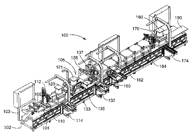
According to a further embodiment of the present invention, and with
reference to Figs. 15-17, there is illustrated an automated fuel cell assembly
apparatus 100 for facilitating automated assembly of fuel cells of varying
technologies. The automated fuel cell assembly apparatus 100 is a robot
assisted automated assembly line by which fuel cell layers are positioned,
stacked, bonded, and output in a progressive assembly line fashion, and
without
operator intervention.
At the start of the fuel cell assembly apparatus 100, a web converting
apparatus 102 is situated for converting a web of a fuel cell membrane to
individual fuel cell membrane sheets and positioning such membrane sheets to a
19
CA 02480950 2004-09-30
WO 03/085764 PCT/US03/04275
predetermined orientation for subsequent processing at an adjacent process
station of the assembly apparatus 100. A web unwind unit 103 presents an end
portion of a membrane web to the web converting apparatus 102.
The web converting apparatus 102 includes a staging station 104 which
incorporates a first vacuum assembly coupled to a vacuum distribution plate.
The
vacuum assembly is selectively actuated during web processing by a controller
of
the automated fuel cell assembly apparatus 100. A positioning station 110
located adjacent to the staging station 104 includes a controllable
positioning
table and a second vacuum assembly fluidly coupled to a vacuum distribution
plate of the positioning station 110. The vacuum assembly of the positioning
station 110 is selectively actuated during web processing by the controller.
The controller may comprise one or several programmable devices, such
as processors, that execute program instructions to coordinate the activities
of
various elements of the fuel cell assembly apparatus 100. The controllers) may
be on-board devices, but may also be located remotely of the fuel cell
assembly
apparatus 100. If located remotely, the controllers) are coupled to the fuel
cell
assembly apparatus 100 using appropriate hardwired or wireless connections.
The positioning station 110 is mounted for movement with multiple degrees
of freedom, and can be moved axially with respect to an x-axis and a y-axis,
and
rotationally about a z-axis under control of a controller. The positioning
station
110, under control of the controller, cooperates with a vision system 112
situated
above the positioning station 110 to modify the position of an individual
membrane sheet after the membrane sheet has been cut from the membrane
web by a cutter 106. The vision system 112 includes one or more cameras to
detect the orientation of a membrane sheet cut from the membrane web.
A robot 114 is controllably moveable between the staging station 104 and
the positioning station 110 via transport frame, and is preferably capable of
moving on the transport frame to processing locations beyond the positioning
station 110. The robot 114, according to one configuration, is a three axis
(x, y, z)
servo and pneumatic driven mechanism that is controlled to pull the membrane
web via a vacuum chuck to the staging station 104 and positioning station 110,
and transfer individual membrane sheets from the positioning station 110 to a
CA 02480950 2004-09-30
WO 03/085764 PCT/US03/04275
downstream process location. The precise orientation of the individual
membrane
sheet established by the positioning table 110 is maintained as the robot 114
transports individual membrane sheets from the positioning station 110 to the
downstream process location.
The web converting apparatus 102 can further include an optical inspection
device, such as a camera, for inspecting the membrane web in order to detect
defects in the membrane patterns, such as completeness of the catalyst
patterns
of the web. The inspection device can also include a device for inspecting one
or
both of a size and a quality of the catalyst patterns of the web.
The separate catalyst sheets produced at the output of the web converting
apparatus 102 are accurately positioned by the positioning station 110 for
processing at a subsequent processing station. The robot 114 moves into
position above a separate catalyst sheet, now repositioned to its
predetermined
orientation, grasps the separate catalyst sheet via the vacuum chuck, and
moves
the separate catalyst sheet to a subsequent processing station, all the while
maintaining the predetermined orientation of the separate catalyst sheet. A
web
converting apparatus 102 well suited for incorporation in the automated fuel
cell
assembly apparatus 100 shown in Figs. 15-17 is disclosed in commonly owned
copending application entitled "Apparatus and Method for Converting a Fuel
Cell
Membrane Web to Precisely Positioned Membrane Sheets," filed concurrently
herewith under Attorney Docket No. 57630US002.
Individual catalyst sheets may be subsequently processed by a cutter
station 120. According to one embodiment, the cutter station 120 includes a
platen cutting press which incorporates a unique cutting die apparatus. The
cutting die apparatus incorporates one or more bearers or stops built into the
cutting die. The built-in bearers operate to control the stroke of a cutting
press.
Integration of one or more stops or bearers built into the cutting die
advantageously eliminates the need for stops arranged external of the cutting
die.
Such external stops are known to be expensive and require careful adjustment
by
a skilled machinist after each die change. The height of the bearer or bearers
of
the cutting die apparatus matches the height of the cutting surface of the
cutting
die apparatus. Because the heights of the bearer and cutting surfaces are
21
CA 02480950 2004-09-30
WO 03/085764 PCT/US03/04275
matched on the cutting die, the risk of crushing the cutting surFace is
significantly
reduced, if not eliminated.
Each cut membrane layer is subsequently transported from the cutting
station 120 to an MEA stacking station 105 at the appropriate time by the
robot
114. A cutting die and apparatus well suited for incorporation in the cutting
station 120 of the automated fuel cell assembly apparatus 100 shown in Figs.
15-
17 is disclosed in commonly owned copending application entitled "Compliant
Cutting Die Apparatus for Cutting Fuel Cell Material Layers," filed
concurrently
herewith under Attorney Docket No. 57631 US002.
The stacking station 105 includes a cathode FTL magazine 115 and an
anode FTL magazine 117 within which a respective stack of cathode and anode
FTLs are made available for automated stacking at the stacking station 105. An
optional gasket unwind/cutter station 121 may be situated adjacent the
stacking
station 105 for providing a cut gasket that can be incorporated around the MEA
structure. The stacking station 105 further includes an FTL robot 140, flip
mechanism 130, shuttle 133, and assembly robot 132 that cooperate to handle,
transport, and precisely position cathode and anode FTLs moved from respective
magazines 115, 117 to build nests 135, 137 in a coordinated manner. Cathode
and anode FTLs are moved in an a coordinated manner with respect to
movement of cut membrane layers by robot 114 during an MEA stacking
operation.
An exemplary pick and place apparatus for destacking/singulating and
transporting cathode and anode FTLs with high precision is disclosed in the
previously incorporated application entitled "Apparatus and Method for
Singulating
Porous Fuel Cell Layers Using Adhesive Tape Pick Head," filed under Attorney
Docket No. 57424US002. The disclosed apparatus may also be employed to pick
and place non-porous membrane layers, although robot 114 employs a vacuum
chuck to facilitate membrane layer transport and placement in the embodiment
shown in Figs. 15-17.
Fixture handling robots 150 (load robot) and 170 (unload robot) coordinate
the handling, transport, and positioning of fixture pallets that are used to
facilitate
automated MEA stacking operations. If desired, the fixture handling robot 150
22
CA 02480950 2004-09-30
WO 03/085764 PCT/US03/04275
applies silicone to the fixture pallets prior to use in stacking operations. A
stacking apparatus and methodology described hereinabove is well suited for
stacking cathode FTLs, anode FTLs, and membrane layers during automated
MEA construction. Exemplary fixture pallets are disclosed in the previously
incorporated application entitled "Fixture Pallet Apparatus for Automated
Assembly of Fuel Cell Material Layers," filed concurrently herewith under
Attorney
Docket No. 57422US002.
A press robot 160 coordinates the transport of MEA stacks through a
number of presses, including a heated press 162 and a subsequent cooling press
164. A bonded MEA is then moved by the press robot 160 to a separation
apparatus 172. The separation apparatus separates an MEA from its fixture
pallet assembly subsequent to MEA bonding. The separation apparatus includes
a base, having a first port, which is adapted to receive the fixture pallet
assembly,
such that the first port is in fluid communication with a first surface of the
MEA via
a porous region of the first fixture pallet. A gripper assembly, mounted for
movement on a support, includes a gripper mechanism and a second port. The
second port is in fluid communication with a second surface of the MEA via a
porous region of the second fixture pallet. The first and second ports are
selectively pressurized and evacuated to separate the first and second
surfaces
of the MEA from the first and second fixture pallets, respectively. The
gripper
assembly is adapted to releasably grip a pair of opposing edges of the second
fixture pallet and to move the second fixture pallet out of proximity with the
first
fixture pallet.
According to one approach, the first and second fixture pallets are initially
stabilized. While the second fixture pallet is stabilized, the first fixture
pallet is
pressurized to cause the first surface of the MEA to separate from the first
fixture
pallet. While the first fixture pallet is stabilized, the second fixture
pallet is
pressurized to cause the second surface of the MEA to separate from the second
fixture pallet. According to one particular approach, a vacuum is applied to
the
second fixture pallet and second surface of the MEA while pressure is being
applied to the first fixture pallet and first surface of the MEA, and,
subsequently,
vacuum is applied to the first fixture pallet and first surface of the MEA
while
23
CA 02480950 2004-09-30
WO 03/085764 PCT/US03/04275
pressure is being applied to the second fixture pallet and second surface of
the
MEA. The second fixture pallet is then moved out of proximity with the first
fixture
pallet to permit removal of the MEA from the first fixture pallet.
A separation apparatus 172 well suited for incorporation in the automated
fuel cell assembly apparatus 100 shown in Figs. 15-17 is disclosed in commonly
owned copending application entitled "Apparatus and Method for Separating a
Fuel Cell Assembly from a Bonding Fixture," filed concurrently herewith under
Attorney Docket No. 57652US002.
Once separated, the bonded MEA is moved by an unload robot 174 to an
MEA cutting press 180. After trimming of the MEA by the MEA cutting press 180,
the processed MEA is moved to an output conveyor 190 by the unload robot 174.
The processed MEA can be packaged or otherwise handled for subsequent
incorporation in fuel cell devices.
The foregoing description of the various embodiments of the invention has
been presented for the purposes of illustration and description. It is not
intended
to be exhaustive or to limit the invention to the precise form disclosed. Many
modifications and variations are possible in light of the above teaching. It
is
intended that the scope of the invention be limited not by this detailed
description,
but rather by the claims appended hereto.
24