Note: Descriptions are shown in the official language in which they were submitted.
CA 02481024 2004-10-O1
1~LECTR]~~ TOOTHBRUSH
B.A.CK.GR.OUND AND SUMMARY OF THE INVENTION
[ooal~ This invention rel0.tes to an electric toothbrush with a Iza~adle and a
brush member. The brush member has a brush head and a connecting rod which
can be set by means o~ a gear into a ~slxding movement reciprocating
longitudinally. Ix~ the electric toothbrush the bristle holders axe held
rotatably in
the brush head in a bristle holder plate. The bristle holders can be set into
an
oscillatory rotatzn.g movement by meazxs of the connecting rod. The brush head
can be set into oscillatory movement about the longitudinal axis of the
toothbrush by means of the gear.
[0002] :A,z~. electric toothbrush of the above type is the subject matter of
US
9;,989,28'7. In the toothbrush, disclosed in this patent, a connecting xvd is
faxed
non-rotatably in the brush member. The brush member is connected rotatably
about its longitudinal axis relative to the haxlrlle. The gear in. the handle
produces both the oscillatory movement and the s3.i.diz~g movement. Owing to
the
oscillatory movement of the conneeting rod about its longitudinal axis, the
entire
brush member oscillates at the same time about its longitudinal axis so that
when using the toothbrush, one can hold only the handle and zaot the
comparably
large brush x~nember.
[0008] In the prior art toothbrush the gear is constructed in such a manner
that the design of the two m.ovexnents that are produced is narrowly defined,
because a single eccentric produces both movements and, therefore, a change in
1
CA 02481024 2004-10-O1
its eccentricity, far example for the purpose of enlargi~ag the sliding
movement,
simultaneously leads to an enlargement of the oscillatory movez~o.ez~t.
[0004] US 4,'710,935 also shows an electric toothbrush, in which one gear is
provided for sliding movement and one gear is provided for oscillatory
xx~oveznent, whereby each geaz~ has its own eccentric. Thus, both movements
can
be dimensioned independently of each other, fiawever, the construction of the
toothbrush, according to this patent, is very complicated an the whole because
it
has a plurality of gears and pinions, a feature, for example, that is
illustrated in
k~.gure 1 of the patent.
[0005a ~1' 0 $1,$ 97? also shows an electric toothbrush, wherein the brush.
member cannot be moved and the brush holder, housed izx the toothbzwsh head,
carries out an oscillatory movexzxent. T~owever, this brush holder has
stationary
bx-istles and no individual tufts of bristles that cazi. oscillate
izidividually about its
longitudinal axis.
[0006] The present invention is based on the problem of designing an
electric toothbrush of the type described above ixz such a ~xzan,nex that both
az~.
oscillatory movement of the individual bristle holders and an oscillatory
swivel
movement of the entire uz~it of bristle holders are possible with simple
zr~earzs,
without having tv cz~ove thereby the ezztiure brush zz~eznber.
[0007) This problexz~. is solved by means o~ the xz~ve~ation in that the
bristle
holder plate in the brush head is held so as to oscillate about a shaft
running in
the longitudinal direction of the toothbrush; and the brush member is
connected
2
CA 02481024 2004-10-O1
non-rotatably to the handle, and that the gear for swiveling the bristle
holder
plate is designed relative to the brush zxa.ember.
[0008] This design makes it possible to nan-rotatably connect the brush
member to the handle in the conventional maian,er; and to provide to this end
a
simple coupling, for example, a bayonet fastez~er. x'hus, the use of the
toothbrush is simultaneously more comfortable, because in so doing ox~e caz~
also
grasp the handle, because it does not move. Furthermore, the energy
consumption of the toothbrush is less than. iz~ the conventional toothbrush,
because only one relatively small bristle holder plate must be swiveled and
not
the entire brush member.
(0009] Xt is advantageous if, according to a ~uxthex aspect o~ the invention,
the gear ~or pz~oducing an oscillatory movement of the co~ecti~ag rod about
its
loxa.gitudinal aazis is ~oxxz~.ed, az~d if the connecting rod is held, such
that it rotates
relative to the brush member about its longitudinal axis, a~ad if the
connecting
rod rests ~xrith its front end so as to slide axially against the bristle
holder plate.
In such a designs the connecting rod is set into motion oscillating about its
lozagitudinal a~ci~s. Aaa~d the motion in the brush head is transferred
directly to the
bristle holder plate.
(0010] 'I'he space conditions in the brush head are used optizxially i_~ the
front end of the connecting rod is bent at right angles and is oriented
parallel. to
the lor~gitudinal a~cis of the connecting rod.
3
CA 02481024 2004-10-O1
[0011] The electric toothbrush is especially ecox~.oazical to produce if the
shaft in the brush head is held on both sides of the bristle holder plate a.nd
projects with its free end into the connecting rad that is bent at right
angles.
Owing to this design, the shaft can swivelably hold not only the bristle
holder
plate, but also the front area of the connecting rod.
[0012] The gear as designed especially simple xf it is formed in the handle
by mea~as of an eccentric, oriented at right angles to the toothbrush shaft
axed
thus also at right angles to the connecting rod; and a guide member of the
toothbrush shaft is formed with a guide, which is axi,ented at right angles to
the
longitudinal axis of the toothbrush shaft, and which reaches over tb.e
ecceo,tric.
[OOIg'] The means for generating the oscillatory movement and the sliding
movement are designed especially simple, if, according to another aspect of
the
invention, the gear is formed exclusively fox generating a sliding movement of
the toothbrush shaft; and, in addition to the gear, a swivel gear is provided
fox
generating the swiveling movement of the toothbrush shaft.
[OOl~j The swivel gear is economical to manufacture, if it has a twisted
flattening on the toothbrush shaft and a radial projection which is stationary
in
the housing and rests against the flattex~.i~.g.
[0015] As an alternative, however, it i.s passible to provide that the swivel
gear has a slanted groove which runs radially into the toothbrush shaft and
into
which projects a radial projectioz~ that is stationary in the housing.
4
CA 02481024 2004-10-O1
[001_6] The brush member, which must be replaced from time to time
because of wear or contamination and must be on hand over and over again
when several persozis use the toothbrush, its especially economical to
manufacture i~ the swivel gear is disposed in the handle, just like the gear
fox the
sliding movement.
[x017] Az~other very simple embodiment of the invention resides i.n the fact
that the swivel gear is disposed iz~ the brush head and has a groove, which
runs
obliquely to the slidizxg direction of the connecting rod and into which
projects an
arm, which is oriented radially to the swivel shaft of the bristle holder
plate aa.d
is connected stationarily to the bristle holder plate. However, it is also
possible
to provide that the bristle holder plate in the toothbrush bead is mounted
swivelably an a swivel shaft, which is oriented parallel to the longitudinal
a~cis of
the brush member, on two opposing sides; and the coz~x~ectiu-~g rad in the
brush
member is guided non-rotatably.
[0018] When the gear is supposed to produce the sliding movement and the
oscillatory movement of the toothbrush shaft, it is especially easy to design
if it
has a spherical head, designed as an eccentric, and the toothbrush shs~t
reaches
with a ring, offset radially to its lor~gitudinal axis, over this spherical
head-
[0019] Zx~ summary it trust be emphasized that the bristle tufts can be
pressed or cemented into the respective bristle holder ox held ixa the
zespective
bristle balder through injection molding with plastic. Instead of with
eccentric
pins and transverse grooves, the reciprocating rotating movement of the
bristle
CA 02481024 2004-10-O1
holders with the bristle tufts can also be generated in a different way, for
example, by rxxeans of a gearwheel on each bristle holder and rack teeth on
the
connectixxg rod. The holders of the tufts o~ bristles can be made o~ material
that
is different from that of the rest of the toothbrush. On the whole, the
inventive
toothbrush is designed such that it can be manufactured quite easily from
injection molded parts.
(0020] Other objects, advantages and novel features of the present
invention will become apparent ~rom the Following detailed description of the
invention when considered in conjunction with the accompanyixlg drawix~.gs.
BRIEF DESCRIPTION O~' THE DRAWINGS
[0021] Fig, is 1 a longitudinal view of a toothbrush accozding to th,e present
invention;
[0022] Fxg. 2 is a perspective longitudinal view in cross-section of a gear
area i.z~
the handle of the toothbrush;
[0023] T"ig. 3 is a perspective view, partly broken away for illustrative
clarity,
of a second embodimez~t of the gear area;
[0024] Fig. 4 is a perspective view, partly broken away for illustrative
clarity,
of a swivel gear for the toothbrush shaft;
[0025] Figure 6 is perspective view, partly brol~en away for illustrative
clazity,
of a second embodiment of a swivel gear for the toothbrush shaft;
6
CA 02481024 2004-10-O1
[0028] Fig. 6 is a perspective view, partly broken away for illustrative
claritp,
of a modified ezubodizxxent of the toothbrush head;
[0027] ~'xgure 7 is a transverse cross-sectional view of anothez~
ezz~,bodznaent of
the toothbrush head; and
[0028] Fig. 8 is a perspective longitudinal view, partly broken away for
illustrative clarity, of the front area of an embodiment of the inventive
toothbrush.
DETAILED DESCRIPTION OF THE PREFERRED EMBODIMENTS
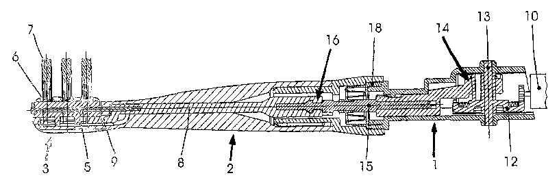
[U029] Referring to Figure 1, there is sh.owza, axx electxic toothbztts'h,
which
has a handle 1 and a brush member 2, desigzaed as a snap an brush. In the
front
area the brush member 2 forms a brush head 3, which accepts a bristle holder
plate 4 (k'ig. ~). x'has bristle holder plate 4 is mounted swivelably on a
shaft 5,
which is held ix~ the brush head 3 and which runs in the longitudinal
direction of
the toothbrush.
[0030] The bristle holder plate 4 accepts rotatably several cylindrical
bristle holders 6 with tufts of bristles 7. Inside the brush member 2 a
connecting
rod 8 can be slid axially and rotated. This corxnecting xod $ has ara, er~d 9,
which
is bent at xxght angles and which xests agaixxst the bristle holder plate 4
and is
held swivelably on a free end of the shaft 5. Owing to its oscillatory
movement
about the longitudinal axis of the connecting rod 8, the offset end 9 can set
the
bristle holder plate 4 i.z~to a~a oscillatory ~x~.ovezxxez~t about the shaft 5
and also
7
CA 02481024 2004-10-O1
provides for a~ reciprocating rotation of the bristle holders 6 with the tufts
of
bristles 7 owing tv the reciprocating sliding movement, or,~iented in the
direction
of the longitudinal axis.
[0031] The handle l has a motor 10, which is shown to some degree and
which drives a crown wheel 7,2 by means of a pinion 11. This crowzi wheel 12
is
~m.ounted rotatably on a crown wheel shaft 13, oriented at right angles to the
connecting rod 8. The crown wheel 13 is a part of a gear l4, by means of
which, a
toothbrush shaft lb of the handle 1 is set into a combined sliding and
oscillatiuag
movement by zrieans of the revolvixag rotating movement of the pinion 11. The
toothbrush shaft 15 is connected to the connecting rod 8 by means of a
disconnectable coupl~g 16 in such a manner that it carries out the same
movement as the toothbrush shaft 15. In addition, it is clear from Figure 1
that
the brush nnember 2 has a housing 17, which is slid on a housing shoulder 18
of
the handle x, where it is secured a~rially by means of a bayonet lock, which
is not
shown.
[oos2~ Figmre 2 shows a possible embodiment of the gear 14 in the handle
1. As in Figure 1, one can see the crown wheel 12 with the crown wheel shaft
13.
On this crown wheel shaft x3 is disposed eccentrically a spherical head 19,
over
which the toothbrush shaft 15 reaches with a xin,g 20, ncxolded to the shaft
16.
This ri~ag 20 is oriented such that its ring plaza.e extez~.ds parallel to the
longitudinal axis o~ the toothbrush shaft 15 owing to a connecting piece 21,
runzaing obliciuely away from the toothbrush shaft 16 to the zing 20. Owing to
the revolving xz~.ovemezxt of the spherical head 19, the toothbrush shaft 15
moves
8
CA 02481024 2004-10-O1
back az~,d forth in the longitudizaal direction, thus making the sliding
movement
mentioned earlier. ,A,t the same time it is swiveled back az~.d Forth about
its
longitudinal axis. Thus, in this embodi.znent the gear 14 represents
simultaneously a sliding gear and a swivel gear for the toothbrush shaft 15.
[0038) Figure 3 depicts an embodiment of the gear 14 that is modified
compared to that of Figure 2. Thus, the crown wheel shaft I3 and the crown
wheel 12 axe Connected non-rotatably to an eccentric 22, i~astead of a
spherical
head 19. The eccentric projects into a guide 28, which runs at right ax~.gles
and
belongs to a guide member 24 of the toothbrush shaft 15. Tb.e guide 23 has a
width equivalent to the diameter of the eccentric 22, but in its transverse
direction it is so long that the eccentric 22 does not rest in the transverse
direction agaixxst the lateral limits of the guide 23. Thus, the revolving
movement of the eccentric 22 bxzzzgs about only a sliding moveaoae~at of the
toothbrush shaft 15. Thus, in this embodiment the gear 14 is only a sliding
gea~c
and not a combined sliding and swivel gear. Zzx this embodiment a separate
swivel gear 2b, which can be fvrtxxed by means of a twisted flatteniz~g 26 and
a
projection 2~, which is oriented radially toward the inside and rests against
the
flattening and belongs to the housing 17, serves to produce the swivel
movement
of the toothbrush shaft.
[0034] The construction and the function of this swivel gear 25 can be seen
the
best in Figure 4. Compared to Figure 3, it significantly enlarges a sub-area
of
the toothbrush shaft 15 with the twisted flattening 26, against which the
projection 27, designed as a pin in this example, rests. rt shows that the
9
CA 02481024 2004-10-O1
toothbrush shat 15 must rotate clockwise, if it is slid to the right, as shown
in
Figure 4. Correspondingly, it must rotate cowoterclockwise if it is moved out
of
its right end position (not illustrated) back into the indicated left end
position.
[0035] The swivel gear, according to Figure 5, has, i_ustead of the flattening
26, an obliquely running groove 28, which leads radially into the toothbrush
shaft 15, and into which the projection 2? projects radially. Correspondingly
the
reciprocating oscillatory rx~ovement of the toothbrush shaft 15 is realized
autarnatically if the toothbrush shaft 15 slides to the right and the left,
when it
thus executes its sliding zxiovement produced by the gear 14.
[0036] Figure 6 shows that the swivel gear 25 can also be disposed in the
brush head , 3. In so doing, the front and 9 of the connecting rod 8 has an
obliquely running groove 29, into which, projects the bristle hoidex plate 4
with
an arm 3fl, which is attached stationarily to the shaft. The bristle holder
plate 4
is held swivelably in the brush head 3 by means of a swivel shaft 85, which
runs
offset parallel to the longitudinal axis of the connecting rod 8. In this
embodiment the conz~ecting rod 8 does not make any oscillatory movement about
its longitudinal axis, but rather only a lifting movement in the direction of
its
longitudinal axis. The slanted groove 29 leads in connection with the arm 30
to
the bristle holder plate 4 swiveling back and forth about the swivel shaft 35.
[0037] Figure 7 shows in detail how the brush head 3 can be designed in
the embodiment according to Figures 1 to 5. The bristle holder plate 4 is
mounted in turn in the housiz~g 1'7 of the bx-ush head 3 such that it
oscillates
XO
CA 02481024 2004-10-O1
about the shaft 5, ring in the longitudinal direction. Furthermore, it shows
ho~ov the tufts of bristles 7 are held in the bristle holder ~. The bristle
holder 6 is
inserted rotatably into the bristle holder plate 4 and has an eccezatxic pin
31,
which projects into a tran.svexse groove 32 of the front end 9 of the
cozuaectinag xvd
8. When the front end 9 e~zecutes its reciprocating sliding movement, which is
oriented perpendicularly to the drawing plane in Figure 7, then the bristle
holder
6 swivels about an axis of rotation 33.
[403$] The right hand side of Figure ? shows only one borehole 34 in the
bristle holder plate 4. A bristle holder 6 with tufts of bristles ? must also
be
inserted into said barehole.
[0039] Figure 8 serves to further illustrate the design of the toothbrush
according to Faguzes z, 3 and ?. One can sEe there the toothbrush shaft 15,
which is set by the gear 7.4 in the handle 1 into the reciprocating sliding
movement axed the oscillatory rotating movement which is transferred from the
toothbrush shaft 15 to the connecting rod 8 izx the brush zziember 2.
Fuxthern:~ore, it is evident that the front end 9 of the connecting rod $ has
altogether three transverse grooves 32, 32' and 32", so that three tufts of
bristles
?, T and ?" can be set into an oscillatory rotati~z~g zuovemeut, What was not
illustrated was that three tufts of bristles ? are also fixed rotatably an the
right
side of the toothbrush head 3.
11
CA 02481024 2004-10-O1
[0040] This application, claims the priority of German patent application
No. 102 X4 803.1, fled April 4, 2002, the disclosure of which is expressly
incorporated by reference herein.
[0041] The foregoing disclosure has been set forth merely to illustrate the
invention and is not intended to be liomiting. Since modifications of the
disclosed
embodiments incorporating the spirit and substance of the ixivention may occur
to persox~.s skilled in the art, the invention should be construed to include
everything withi~a the scope of the appended claixzss azad equivalents
thereof.
12