Note: Descriptions are shown in the official language in which they were submitted.
CA 02481303 2004-10-O1
WO 03/086239 PCT/US03/10460
1
1NTRAVASCULAR FLOW MODIFIER AND REINFORCEMENT
' DEVICE WITH CONNECTED SEGMENTS
RELATED APPLICATIONS
This is a continuation-in-part of application Serial No. 09/747,456, filed
December 22,
2000 which is a divisional of application Serial No. 09/122,243 filed July
24,1998, now U.S.
Patent No. 6,165,194.
BACKGROUND OF THE INVENTION
Field of the Invention:
The present invention relates to a reinforcement device, i. e., stent, for use
within a body
vessel, and more particularly, to a stent for use in combination with
vasoocclusive devices
placed in an aneurysm fox the purpose of occluding an axleurysm, that provides
reinforcement
for the area of the blood vessel in the vicinity of the aneurysm.
Description of the Related ArE:
The progress of the medical arts related to treatment of vascular
malformations has
dramatically improved with the availability of intravascular devices capable
of operating
entirely within the vasculature. Thus, many highly invasive surgical
procedures and inoperable
conditions have been treated by the use of an expaxiding number of devices and
procedures
designed for those purposes. One particularly useful development in the
medical arts has been
the ability ~to treat defects in relatively small arteries and veins, such as
those in the
neurovascular system, by use of an infusion catheter and the placement of
embolic coils and
the like in areas where the malformation is likely to cause or has already
caused a rupture in
the blood vessel. More specifically, it has been found that the treatment of
aneurysms by such
devices and procedures allows the medical practitioner to avoid otherwise
risky medical
procedures. For example, when the placement of the defect is in the brain, a
great deal of
difficulty is presented to treatment of small defects in the blood vessels
with conventional
surgical techniques. For these reasons, the progress in development of devices
to treat such
defects has been encouraged and has produced useful results in a wide variety
of patients.
One aspect of these surgical treatments is that an aneurysm or other
malformation is
symptomatic of a general wealcening of the vasculature in the area containing
the aneurysm,
and mere treatment of the aneurysm does not necessarily prevent a subsequent
rupture in the
CA 02481303 2004-10-O1
WO 03/086239 PCT/US03/10460
2
surrounding area of the vessel. Moreover, it is often desirable to provide a
means to prevent
the migration of the vasoocclusive devices, such as coils and the like, out of
the aneurysm in
the event that the aneurysm has a relatively large neck to dome ratio.
Stents, which are tubular reinforcements inserted into a blood vessel to
provide an open
path within the blood vessel, have been widely used in intravascular
angioplasty treatment of
occluded cardiac arteries. In such a case, the stmt is inserted after an
angioplasty procedure
or the like in order to prevent restenosis of the artery. In these
applications, the stems are often
deployed by use of inflatable balloons, or mechanical devices which force the
stem open,
thereby reinforcing the artery wall in the clear through-path in the center of
the artery after the
angioplasty procedure to prevent restenosis.
While such procedures may be useful in certain aspects of vascular surgery in
which
vasoocclusive devices are used, the wealmess of the vasculature and the
inaccessibility of the
interior of the aneurysm from the vessel after the placement of such a scent,
places limits on
the applicability of such stems in procedures to repair aneurysms,
particularly neuro-vasculax
aneurysms. Furthermore, the use of placement techniques, such as balloons or
mechanical
expansions of the type often found to be useful in cardiac surgery are
relatively less useful in
vasoocclusive surgery, particularly when tiny vessels, such as those found in
the brain, are to
be treated.
Hence, those skilled in the art have recognized a need for a stmt compatible
with
techniques in vasoocclusive treatment of aneurysms that provides selective
reinforcement in
the vicinity of the artery, while avoiding any unnecessary trauma or risk of r
upture to the blood
vessel. The need for a scent with structural integrity that both allows for
placement without
a balloon or mechanical expansion and provides sufficient radial support when
in a deployed
state has also been recognized. The present invention provides these and other
advantages.
SUMMARY OF THE INVENTION
Briefly, and in general terms, the invention relates to vaxious configurations
of stems
designed for use in the treatment of aneurysms and ischemic diseases.
In a first aspect, the invention relates to a scent for use in the
intravascular treatment
of blood vessels. The stmt includes a generally cylindrical frame formed of an
elongate
resilient wire. The two free ends of the wire extend distally from the
proximal end of the
frame and transition at a first point to a pair of opposed first arcuate
sections. Thereafter the
CA 02481303 2004-10-O1
WO 03/086239 PCT/US03/10460
3
frame transitions to a pair of opposed first IongiW dinal sections for a
length to a second point
and then transitions to a pair of opposed second arcuate sections and a pair
of opposed second
longitudinal sections. The frame proceeds similarly in this pattern to the
distal end of the
frame. The stmt further includes a plurality of connecting segments which
connect a plug ality
of opposed longitudinal sections.
In detailed aspects, the frame is formed from a material having properties
that provide
it with a predeployed essentially flat configuration and a deployed generally
cylindrical
configuration. In other detailed aspects, the connecting segments are located
on both sides of
the frame or alternatively only one side of the frame. In another detailed
aspect, the connecting
segments comprise a pair of bands. One of the bands is wrapped around one of a
pair of
opposed longitudinal sections. The first and second bands are secured
together, thereby
connecting the opposed longitudinal sections. In yet another detailed facet,
the connecting
segments comprise a single band secured around both of an opposed pair of
longitudinal
sections. In still another detailed facet, the connecting segments comprise a
piece of solder
spanning between a pair of opposed longitudinal sections.
In another aspect, the invention relates to a stmt for use in the
intravascular treatment
of blood vessels that includes a first half frame and a second half frame.
Each of the half
frames includes a plurality of arcuate sections connected by longitudinal
sections. The stem
further includes a plurality of connecting segments. These segments secure a
plurality of first
half frame longitudinal sections to a plurality of second half frame
longitudinal sections such
that the fixst half frame and the second half frame form a cylinder.
In a detailed aspect, the arcuate sections of the stmt have a chevron
configuration when
viewed from a first direction and a bowed configuration when viewed from a
second direction
approximately 90 ° offset from the first direction. In further detailed
aspects, the point of the
chevron is directed toward the proximal end of the stmt while the arcuate
sections bow toward
the proximal end of the stmt. In still fwther detailed aspects, the connecting
segments are
located on only one side of the cylinder or alternatively on both sides of the
cylinder.
In another detailed facet of the invention, each of the first and second half
frames are
formed from a piece of elongate resilient wire with a first end extending
distally from the
proximal end of the half frame. The wire transitions at a first point to a
first arcuate section
and then transitions to a first longitudinal section for a length to a second
point. Thereafter the
wire transitions to a second arcuate section and a second longitudinal section
and proceeds
CA 02481303 2004-10-O1
WO 03/086239 PCT/US03/10460
4
similarly to the distal end of the half frame. In another detailed aspect of
the invention, the
first and second half frames and the connecting segments are formed from a
single piece of
hypotubing with portions removed to form first and second half frame patterns
and the
plurality of connecting segments. Each of the half frame has an alternating
arcuate section -
S longitudinal section configuration as described above with respect to the
wire configuration.
With respect to both the wire configuration and the hypotubing configuration,
each of the half
frames may have a predeployed essentially flat configuration and a deployed
generally
cylindrical configuration and/or a predeployed radially compressed
configuration and a
deployed generally cylindrical configuration.
In another aspect, the invention relates to a stmt for use in the
intravasculax treatment
of blood vessels that includes a first half frame and a second half frame,
each of which
includes a plurality of arcuate loop sections which comprise a pair of arcuate
sections
connected at each end by a longitudinal connecting section. The stem also
includes a plurality
of cormecting segments that secure a plurality of first half frame arcuate
loop sections to a
1 S plurality of second half frame arcuate loop sections such that the first
half frame and the
second half frame form a cylinder.
In a detailed aspect, the first and second half frames are formed from a
material having
properties that provide it with apredeployed radially compressed configuration
and a deployed
generally cylindrical configuration. Tn other detailed facets, the comzecting
segments are
located on only one side of the cylinder or alternatively are located on both
sides of the
cylinder. In another detailed aspect the first and second half frame arcuate
loop sections are
secured such that the first half frame arcuate loop sections are
longitudinally offset from the
second half frame arcuate loop sections.
The devices, systems and methods of the present invention provide important
2S advantages over prior art devices in that they eliminate the necessity for
balloon or mechanical
placement devices which can cause unnecessary trauma to the delicate
vasculature which has
already been damaged by the presence of the aneurysm. For this reason, the
invention is
particularly useful to cover and reinforce large neck aneurysms. The presence
of the
longitudinal sections and the connecting segments improves the pushability of
the stmt,
thereby enhancing the ability to deploy and place the stent within the
vasculature, an issue of
considerable impoutance ifneither balloon nor mechanical placement methods are
to be used.
CA 02481303 2004-10-O1
WO 03/086239 PCT/US03/10460
The connecting segments also increase the structural integrity of the stmt and
provide
sufficient radial support when the scent is in a deployed state.
Another advantage of the present invention is that it may be used in arteries
up to renal
size while still providing the benefits of placement without the use of
balloons or mechanical
5 expansions. One significant benef t in such an application is that the flow
through the vessel
is never fully occluded by the placement of the device in the invention, and
it is possible to
place the scent from a free flow guiding catheter that is relatively small in
diameter compared
to the inside diameter of the blood vessel being treated.
While certain features of the invention and its use have been described, it
will be
appreciated by those slcilled in the art that many forms of the invention may
be used for
specific applications in tlae medical treatment of deformations of the
vasculature. Other
features and advantages of the present invention will become apparent from the
following
detailed description taken in conjunction with the accompairying drawings,
which illustrate by
way of example, the principles of the invention.
BRIEF DESCRIPTTON OF THE DRAWINGS
FIGURE. 1 is a perspective view of a scent in a deployed state and configured
in
accordance with one embodiment of the invention, having a frame formed from a
single Loop
of wire formed into a series of arcuate sections and longitudinal connecting
sections and a
plurality of cormecting segments connecting opposed longitudinal connecting
sections;
FIG. 2 is a side view of the deployed stmt of FIG. l;
FIG. 3 is a plan view of the stmt of FIG. 1 in a predeployed, flattened state;
FIG. 4 is a cr oss section of a guiding catheter revealing a plan view of the
stmt of FIG.
3 positioned within the catheter in a predeployed, flattened and compressed
state;
FIG. 5 is a side view of a scent at a transition point between the predeployed
state of
FIGS. 3 and 4 and the deployed state of FIGS. 1 and 2;
FIG. 6 is a side view of a deployed stmt illustrating an alternate
configuration in which
the arcuate sections of the stmt are more densely located in the middle
portion of the stmt;
FIG. 7 is a plan view of a predeployed stmt illustrating an alternate
configuration in
which the radii of the arcuate sections vary along the length of the stmt;
FTG. 8 is an illustration of a mandrel upon which the stmt of FIG. 1 is formed
in one
preferred embodiment of the method of manufacture;
CA 02481303 2004-10-O1
WO 03/086239 PCT/US03/10460
6
FIG. 9 is a perspective view of a deployed stmt configured in accordance with
the
invention having only a frame foamed from a single loop of wire formed into a
series of
transverse arcuate sections and longitudinal connecting sections;
FIG. 10 is a perspective view of a stmt in a deployed state and configured in
accordance with another embodiment of the invention, having first and second
half frames,
each formed from a piece of wire formed into a series of arcuate sections and
longitudinal
connecting sections and a plurality of connecting segments connecting opposed
longitudinal
connecting sections on both sides of the stmt;
FIG. 11 is a plan view of the deployed scent of FIG. 10;
FIG. 12 is a side view of the deployed stmt of FIG. 10;
FIG. 13 is a perspective view of an alternate configuration of the stmt of
FIG. 10 in
which connecting segments are present on only one side of the stent;
FIG. 14. is a plan view of the scent of FIG. 10 is a compressed, predeployed
state;
FIG. 15 is a side view of the stmt of FIG. 10 is a compressed, predeployed
state;
FIG. 16 is a perspective view of a stmt in a deployed state, configured in
accordance
with another embodiment of the invention, having opposed arcuate sections,
opposed
longitudinal connecting sections and connecting segments or hinges on both
sides and formed
from a laser cut piece of hypotubing;
FIG. 17 is a plan view of the deployed stmt of FIG. 16;
FIG. 18 is a side view of the deployed stmt of FIG. 16;
FIG. 19 is a plan view of a scent in a deployed state, configured in
accordance with
another embodiment of the invention, having longitudinally offset arcuate loop
sections, and
connecting segments or hinges only on one side and formed from a laser cut
piece of
hypotubing;
2S FIG. 20 is a side view of the scent of FIG. 19;
FIG. 21 is a rolled out detail of the stmt of FIGS. 19 and 20;
FIG. 22 is a cross section of a vessel with the stmt of FIG. 10 deployed in
the vicinity
of an aneurysm; and
FIG. 23 is a cross section of a vessel with the stmt of FIG. 13 deployed in
the vicinity
of an aneurysm.
CA 02481303 2004-10-O1
WO 03/086239 PCT/US03/10460
7
DETAILED DESCRIPTION OF THE PREFERRED EMBODIMENTS
As shown in the exemplary drawings, which are provided for the purposes of
illustration and not by way of limitation, the device of the present invention
is designed to be
deployed intravascularly without the necessity of balloons or other expansive
elements and can
be deployed from a guiding catheter directly into the axea to be treated. The
intravascular
device of the present invention is particularly useful for treatment of
damaged arteries
incorporating aneurysms and the like, particularly those which are treatable
by the use of
embolic coils or other embolic devices or agents used to occlude the aneurysm.
More
particularly, the device of the invention is particularly well adapted to use
with the types of
catheters used to place such embolic coils in aneurysms, and the device may be
used to
reinforce the area in the vicinity of the aneurysm while allowing placement of
one or more
embolic coils through the gaps in the device, while assisting in the retention
of the embolic
devices within the dome of the aneurysm.
In general, device of the invention is formed of superelastic or shape memory
material,
which, in its deployed configuration comprises a series of opposed arcuate
sections connected
by opposed longitudinal sections. The opposed arcuate sections from a series
of or
circumferential loops. Upon deployment, the device is placed within the
vasculature so that
it extends from a position proximal to a position distal of the aneurysm to be
treated. The
device may be arranged so that an open portion of the device straddles the
neck of the
aneurysm to allow placement of embolic coils and the lilce through the opening
into the
aneuzysm.
In one configuration of the device, placement near the aneiuysm is achieved by
deforming the device into a flattened and compressed state and positioning it
within a guiding
catheter. Once the guiding catheter is placed near the aneurysm, the device is
pushed out of
the guiding catheter by means of a pusher and detached from the pusl2er by a
variety of means
to complete placement of the device. After placement of the device, the pusher
and catheter
ar a withdrawn.
Turning now to the drawings, in which like reference numerals are used to
designate
like or corresponding elements among the several f gures, in FIG. l, there is
shown one
embodiment of an intravascular device 10, i.e., stmt, for use in vasoocclusive
procedures.
The stmt 10 includes a frame 11 and a plurality of connecting segments 13
connecting
portions of the frame.
CA 02481303 2004-10-O1
WO 03/086239 PCT/US03/10460
8
With reference to FIGS. 1 and 2, in one configuration of the stmt 10, the
frame 11 is
formed from a single piece of wire configured as a series of arcuate sections
12 connected by
longitudinal sections 14 to progressively foun an essentially cylindrical
frame. More
specifically, the two free ends 16 of the piece of wire are placed in close
proximity to each
other. A first pair of longitudinal sections 14 extends from the free ends 16.
The wire is then
formed into a pair of arcuate sections 12 extending in semi-circular arcs for
a distance less than
half of the circumference of the frame to a position in which a transition
into a second pair of
longitudinal sections 14 are formed for a second distance 18 at which point
they transition
baclc to another pair of arcuate sections 12 and then proceed in such a
sequence towards a
continuous end loop 20 extending between the most distal longitudinal sections
14 to form the
distal end of the frame. The distance 18 between adj acent arcuate sections 12
is selected such
that the space between adjacent loops is sufficient to allow for the passage
of an embolic
device. The transition 24 between the arcuate sections 12 and the longitudinal
sections 14
have a predetermined radius.
In one embodiment, the wire of the frame 11 is made of a superelastic material
such
as a nicl~el- titanium alloy to allow for easy insertion of the stmt 10 within
a guiding catheter.
The wire may be coated with a corrosion resistant material such as Parylene.
Other materials,
such as shape-memory alloys, may also be used to provide for the dual purposes
of ease of
insertion into a guiding catheter and formation upon deployment into the
desired shape of the
device. One material that is contemplated as a wire from which the frame 11
ca~1 be made is
a stranded cable including one or more radiopaque strands, or which has
radiopaque marl~ers
deployed along its length. Such a stranded cable can be made of a variety of
materials
including stainless steel, shape-memory alloy, superelastic alloy, platinum or
the like or
combinations thereof. While this configuration of the frame 11 is shown in the
form of a
cylindrical wire, those skilled in the art will realize that other
configurations of material may
be used to form the frame, including laminates, flatten wires and laser cut
hypotubing, each
of which are within the scope of the invention.
With continued reference to FIG. l, the frame 11 is configured such that the
longitudinal sections 14 axe arranged in opposed pairs. In accordance with the
invention, one
or more connecting segments 13 span the gap 22 between opposed longitudinal
sections 14
CA 02481303 2004-10-O1
WO 03/086239 PCT/US03/10460
9
to thereby connect the sections. The connecting segments 13 may be on both
sides of the
frame or alternatively (not shown) on only one side of the frame.
In one embodiment, the connecting segments 13 are bands wrapped around opposed
longitudinal sections 14. The band 13 may be made of a plastic material, such
as
polytetrafluoroethylene (PTFE) or a metallic material, such as platinum or
stainless steel. The
ends of the bands 13 are secured together through bonding, crimping or
soldering, depending
on the specific band material. A radiopaque material may be included in the
connecting
segments 13 to aid visibility.
In another configuration (not shown), the connecting segments 13 include two
individual bands, one wrapped around each of the opposed longitudinal sections
14. These
bands are then secured to each other by bonding or soldering. In yet another
configuration
(also not shown), the connecting segments 13 may be a piece of solder spanning
the gap 22
between the opposed longitudinal sections I4.
With reference to FIGS. 3, the stmt 10, prior to deployment in a vessel, can
be made
into an essentially flat configuration in which the free ends 16 of the stmt
are connected to a
deployment device 26 on the distal end of a pusher 28 which fits within a
guiding catheter (not
shown). In this configuration, it can be seen that the arcuate sections 12 are
connected by the
longitudinal sections 14 which become essentially parallel with the
longitudinal axis of the
stem in the deployed configuration. The connecting segments 13 connecting the
longitudinal
sections 14 maintain the opposite sides of the frame 11 generally fixed
relative to each other
and thereby provide increased stability along the length of the stmt. This
increased stability
reduces the possibility of the stmt 10 bending or lcinking during placement of
the stmt in the
guiding catheter and subsequent deployment.
With reference to FIG. 4, prior to placement within a vessel, the stmt 10 is
placed
within a guiding catheter 30 by first attaching the stmt to the deployment
device 26 on the
pusher 28 and then pulling the stmt into the guiding catheter using the
pusher. During this
process the arcuate sections 12 of the flattened stmt 10 become compressed. In
this state the
stent 10 looks like a plurality of stretched linear loops of wire connected in
series. The guiding
catheter 30 is then introduced into the vasculature and positioned near the
area of the
vasculature to be treated. Once positioned, the pusher 28 is pushed in the
distal direction to
extend the stmt 10 from the guiding catheter 30.
CA 02481303 2004-10-O1
WO 03/086239 PCT/US03/10460
With reference to FIG. S, as the stmt 10 is deployed from the guiding catheter
(not
shown) the compressed arcuate sections 12 begin to assume their normally
arcuate shape while
the frame 11 itself begins to assume its cylindrical shape. Eventually, the
stmt 10 returns to
the shape as shown in FIG. 1. During this process, the detachment device 26
separates from
5 the ends 16 of the scent 10 and is withdrawn into the catheter 30 (FIG. 4)
and removed from
the vasculature.
The frame 11 portion of the stem 10 may be formed in various different
configurations.
For example, in one configuration the density of arcuate sections can be
varied from proximal
to distal end in order to provide a relatively gr eater density in an area to
be placed in a portion
10 of the vasculature which is particularly weak or is threatened by
treatment. With reference to
FIG. 6, in one such configuration the scent 10 can be formed to have shortex
longitudinal
sections 14 between the arcuate sections 12 at certain sections of the scent,
for example, the
middle region, and thus provide a higher degree of reinforcement in that
specific area. Such
a configuration has numerous benefits depending on the topology of the damage
to the artery,
and can provide benefits for certain types of treatment therapies.
As another example, the stmt may be configured to have a variable diameter in
the
arcuate sections over the length of the stmt in oxder to provide relatively
greater
circumferential tension against the wall of the vessel in some areas than
others. With reference
to FIG. 7, in one such configuration the stmt 10 may be formed such that the
radii of the
arcuate sections 12 vary along the length of the stmt. In FIG. 7, the radii
progressively
decrease in size from the proximal end to the distal end of the stmt. Other
arrangement are
possible. For example, the radii may tapex down in size from both ends of the
stmt toward the
middle. Any of the preceding configurations allow the stmt to modify the blood
flow
characteristics in the vessel in which the stmt is deployed. hi another
configuration (not
shown), the arcuate sections are formed into an arcuate curve having a radius
that varies over
the length of the loop.
This configuration of the scent may be formed in a number of ways, but there
are
presently two preferred methods ofmanufacture. In a first preferred method
illustrated in FTG.
8, a longitudinal mandrel 32 made of tungsten, ceramic, stainless steel or
other heat resistant
matexial has inserted into it pegs 34 of heat resistant material around which
the wire to be
formed into the frame is wound. The position of the pegs represent transitions
between the
CA 02481303 2004-10-O1
WO 03/086239 PCT/US03/10460
I1
arcuate sections 12 and the longitudinal sections 14 of the frame. The
diameter of the pegs 36
and the spacing of the pegs 38, 40, 42 may be altered in order to provide
certain
characteristics that are desired in the stmt as it is formed. Alternatively,
the mandrel can have
a grooved configuration formed into it in which the wire is placed prior to
heat treatment.
In either method, a single wire is wound progressively down the mandrel
forming
arcuate sections 12 and longitudinal sections 14 until a desired length of the
stmt is reached,
at which point the path is retraced similarly to the position at which the
frame was begun on
the mandrel. The wire can then be heat treated on the mandrel to create a
shape memory or
treated to reach a superelastic state.
After formation, the frame I1 is removed from the mandrel 32 and one or more
connecting segments 13 are secured to opposing longitudinal sections 14. The
connecting
segments 13 are secured to the longitudinal sections I4 using bonding or
soldering processes
well l~nown to those spilled in the art. Thereafter, the scent can be
stretched to be inserted into
a guiding catheter prior to insertion into the vasculature or compressed over
tubing and
I S constrained in a sheath.
As previously mentioned with reference to FIGS. 6 and 7, the stent can be
formed in
a variety of configurations. In other such configuration overlapping of the
arcuate sections 12
and the longitudinal sections 14 create particularly desired characteristics
to the scent and
thereby enhance specific aspects of density or longitudinal pushability for
various applications.
In another configuration, as shown in FIG. 9, the stmt 10 is formed of a
single loop of
superelastic or shaped-memory wire shaped into a series of transverse Ioops
and longitudinal
connecting sections similar to the previously described stmt shown in FIG. 1.
This
configuration, however, does not include the connecting segments 13 (FIG. 1)
as in the
previous stent. It has been noted, however, that due to its single loop
configuration this stmt
may bend and lcinlc along its length while being pulled into or pushed from
the catheter. Such
bending and Icinlcing may damage the structural integrity ofthe stmt. Once
deployed, the stent
assumes its expanded state and provides reinforcement to the vessel wall. In
this regard, the
single loop configuration may not provide sufficient radial support due to the
gaps 22 between
opposing sides of the stem. For these reasons the stmt shown in FIG. 1 is a
preferred
embodiment.
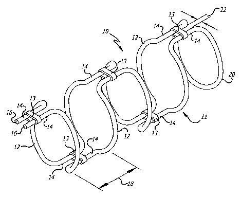
With reference to FIGS.10,1 l and 12, in another embodiment ofthe invention, a
stmt
50 is formed to include a first half frame 52 and a second half frame 54. Each
of the half
CA 02481303 2004-10-O1
WO 03/086239 PCT/US03/10460
I2
frames S2, S4 include a plurality of generally parallel arcuate sections 56
connected by
longitudinal sections 58. In this embodiment, the longitudinal sections S 8
are not linear as in
the previous embodiment but instead are curved. The axcuate sections S6 are
generally
semicircular in shape when viewed along the axis of the stem, bow toward the
proximal end
60 of the stmt when viewed from the top (FIG. 11 ) and have a chevron
configuration, with top
and bottom portions 62, 64 meeting at axz angle 66 pointing toward the
proximal end 60, when
viewed from the side (FIG. 12).
The scent SO also includes a plurality of connecting segments 68. These
segments 68
may be a single band, a pair of bands or solder, as previously described with
reference to the
stmt configuration shown in FIG. 1. The connecting segments 68 secure a
plurality of first
half frame longitudinal sections 58 to a plurality of second half frame
longitudinal sections
S8 such that the first half frame and the second half frame form a cylinder.
In the
configuration of FIG. 10, the connecting segments 68 axe on both sides of the
cylinder. As
such the stmt has improved radial strength. In an alternate configuration, as
shown in FIG.
13, the connecting segments 60 are only located on one side of the cylinder.
As such the scent
has improved collapsing capacity which is beneficial during scent deployment.
With continued reference to FIGS. 10 and 13, each of the first and second half
frames
S2, S4 are formed from a separate piece of elongate resilient wire. In one
embodiment, the
wire is made of a superelastic material such as a nickel-titanium alloy to
allow for easy
insertion of the scent S 0 into a guiding catheter or sheath. The wire may
have either a circular
or flatten cross section and may be coated with a corrosion resistant material
such as Parylene.
Other materials, such as shape-memory alloys, may also be used. One material
that is
contemplated as a wire from which the half frames S2, S4 can be made is a
stranded cable
including one or more radiopaque strands, or which has xadiopaque marl~ers
deployed along
2S its length. Such a stranded cable can be made of a variety of materials
including stainless
steel, shape-memory alloy, supexelastic alloy, platinum or the like or
combinations thereof.
Each piece of wire has a first end 72 extending distally from the proximal end
60 of
the half frame. After a predetermined distance, the wire transitions at a
first point 74 to a first
arcuate section 76 and then transitions to a first longitudinal section 78 for
a length to a second
point 80. The piece of wire then transitions to a second arcuate section 82
and a second
longitudinal section 84 and proceeds similarly to its second end 73 at the
distal end 70 of the
half frame. The first end 72 and the second end 73 of the first half frame S2
and second half
CA 02481303 2004-10-O1
WO 03/086239 PCT/US03/10460
I3
frame 54 may be secured together by a connecting segment 68. Alternatively,
the ends 72, 73
may be left free.
The resilience ofthe wire from which tl2e half frames are formed allows for
the frames
to transition between a predeployed essentially flat configur anon, similar to
that shown in FIG.
3, and a deployed generally cylindrical configuration, as shown in FIG. 10.
This allows for
placement of the stmt in a guiding catheter as previously described.
The resilience ofthe wire, in combination with the bow and chevron
configuration, also
allows for the half frames 52, 54 to transition between a predeployed radially
compressed
configuration, as shown in FIGS. 14 and 15, and a deployed generally
cylindrical
configuration, as shown in FIGS. 10 and 13. With reference to FIG. 14, when
radially inward
pressure is applied to the sides of the stmt, the bowed portions of the adj
acent arcuate sections
56 collapse toward each other. Similarly, with reference to FIG. 15, when
radially inward
pressure is applied to the top and the bottom of the stmt, the top portion b2
and bottom portion
64 of the arcuate sections 56 collapse toward each other. Accordingly, when
the stmt
experiences each of top, bottom and side radially inward pressure the stmt
reduces in size
radially. The reduction in radial size allows for placement of the stmt in a
guiding catheter
or sheath without having to flatten and stretch the stmt as previously
described.
With reference to FIG. 16, 17 and 18, in another embodiment of the invention,
a stmt
90 is formed by laser cutting a piece of hypotubing to form a stmt pattern
including a first
half frame 92, a. second half frame 94 and a plurality of com~ecting segments
96. The
hypotubing may be formed from a shape-memory material similar to that of the
resilient wire
of the pr evious configuration. Since the stmt is laser cut from a piece of
hypotubing there are
no discreet parts such as the described first half frame 92, second half frame
94 and plurality
of connecting segments 96. However, for description purposes these various
parts are referred
to herein.
The first and second half frames 92, 94 axe each patterned to respectively
include a
plurality of generally parallel arcuate sections 98 connected by longitudinal
sections 100. The
arcuate sections 98 are generally semicircular in shape when viewed along the
axis of the stmt,
bow toward the proximal end 102 of the stmt when viewed from the top (FIG. 17)
and have
a chevron configuration, with top and bottom portions 104, 106 meeting at an
angle 108
pointing toward the proximal end 102, when viewed from the side (FIG. 18).
Opposed
longitudinal sections 100 are joined by connecting segments 96 or hinges.
CA 02481303 2004-10-O1
WO 03/086239 PCT/US03/10460
14
In the configuration of FTG. 16, the connecting segments 96 are on both sides
of the
cylinder. As such the stmt has improved radial strength. In another
configuration (not
shown), the stmt may be formed such that the connecting segments 96 axe only
located on one
side of the stent. As such the stmt has improved collapsing capacity which is
beneficial
dtu-ing stem deployment. In either configuration, the stmt 90 is formed from
hypotubing
having resiliency characteristics lilce that of the wire stmt configurations
(FIGS. 1 and 10).
Accordingly, it may be flattened and stretched or radially compressed for
placement in a
guiding catheter or sheath.
With reference to FIGS 19, 20 and 21, in another embodiment of the invention,
the
scent 120 is formed by laser cutting a piece of hypotubing to form a scent
pattern having a first
half frame 122, a second half frame 124 and a plurality of connecting segments
126. The first
and second half frames 122, 124 are each patterned to include a series of
generally parallel
arcuate loop sections 132. Each arcuate loop section 132 includes a pair of
generally parallel
arcuate sections 128 connected by longitudinal sections 130. The arcuate
sections 128 are
generally semicircular in shape when viewed along the axis of the stmt, bow
toward the
proximal end 134 of the stmt when viewed from the top (FIG. 19) and have a
chevron
configuration, with top and bottom portions 138, 140 meeting at an angle 142
pointing toward
the proximal end 134 of the scent, when viewed from the side (FIG. 20).
Opposed acuate loop sections 132 are joined by connecting segments 126 or
hinges.
As with other configurations, the connecting segments 126 may be on only one
side of the
stent or on both sides (not shown). In a preferred embodiment, the half frames
122, 124 are
aligned relative to each other such that opposing arcuate loop sections 132
are longitudinally
offset from each other, in a staggered pattern. Due to the formation of
independent arcuate
loop sections 132, this configuration of the scent may not be longitudinally
stretched. The
combination chevron and bow configuration does, however, allow for it to be
radially
compressed for delivery.
The invention provides numerous important advantages in the treatment of
vascular
malformations, and particularly malformations which include the presence of
aneurysms.
Since the stems do not represent an essentially solid tubular member and do
not require the use
of a balloon or other mechanical device for deployment, they are capable of
deployment from
a guiding catheter which need not occlude the artery as it is put into a
position from Which to
deploy the stent. Furthermore, the stems upon deployment can reinforce the
artery without
CA 02481303 2004-10-O1
WO 03/086239 PCT/US03/10460
1S
occluding access to the aneurysm, thus allowing the stems to be deployed prior
to the
placement of embolic coils or the lilce in the aneurysms. Alternatively,
depending on the
nature of the vascular defect, the embolic coils or other embolic occlusive or
other
vasoocclusive devices can be placed and the stems deployed thereafter to hold
the devices in
the aneurysm.
The present invention also contains numerous advantages over the prior art,
including
enhanced pushability without creating circumferential stress from the loop
section, as is often
found in the case of coil-type intravascular flow modifiers l~nown in the
prior art. The
reinforcement strength of the stems is enhanced by the connecting segments
spanning opposed
sections of the frames. The characteristics of the stmt , such as loop
strength, and the
resilience of the stmt are controlled by several factors including the radii
of the transitions to
the longitudinal sections, the diameter or thicleness of the wire or
hypotubing and the distance
between the longitudinal sections and the arcuate sections which form the
frame.
The collapsibility of the stmt for deployment purposes is a function of
material and
stent configuration. The use of superelastic and/or shape-memory material in
combination
with the unique interconnection between arcuate sections allows for the stent
to be flattened
and stretched for placement within a guiding catheter. The addition of chevron
configured
arcuate sections allows for the stem to be compressed while the use of bowed
arcuate sections
allows for further compression and ease of movement in the distal direction
during
deployment. Thus, the invention provides a wide variety of performance
characteristics that
can be designed as part of the scent configuration.
With reference to FIGS. 22 and 23, two configurations of scents 150, 152 are
shown
deployed within a vessel I54 in the vicinity of an aneurysm 156. The stmt 150
in FIG. 22 is
configured like the stmt shown and described with respect to FIG. 13. This
stmt 150 includes
connecting segments 158 on only one side of the stmt. As shown, the chevron
configuration
of the arcuate sections 160 cause the stmt to expand and fit tightly against
the interior wall of
the vessel. With respect to the free side of the stmt, i.e., the side of the
stmt without
connecting segments 158, it has been noted that the disconnect between the
opposed arcuate
sections decreases the radial strength of the stem on that side and makes the
stmt more
compliant. This compliance allows the stmt to expand to a generally uniform
diameter along
its length without entering into the area of the aneurysm 156. Thus the stem
150 provides
CA 02481303 2004-10-O1
WO 03/086239 PCT/US03/10460
16
support for the vessel 154 in the area around the aneurysm 156 while leaving
room for the
introduction of embolic coils into the aneurysm.
The stmt 152 in FIG. 23 is configured like the stmt shown and described with
respect
to FIG. 10. This stmt 150 includes connecting segments 158 on both sides of
the stmt. As
a result, the stmt has increased radial strength on both sides, is less
compliant than the stmt
shown in FIG. 22 and thus tends to expand into a portion of the area of the
axleurysm 156.
From the above, it may be observed that the present invention provides
significant
benefits to the treatment of vascular malformations, and particularly
aneurysms in the
neurovasculature. ~nportantly, the invention is particularly advantageous when
used in
combination with vasoocclusive devices placed in the aneurysm by intravascular
procedures.
The stems of the present invention may also find application in the treatment
of ischemic
diseases.
It will be apparent from the foregoing that while particular forms of the
invention have
been illustrated and described, various modifications can be made without
departing from the
spirit and scope of the invention. Accordingly, it is not intended that the
invention be limited,
except as by the appended claims.