Note: Descriptions are shown in the official language in which they were submitted.
CA 02481987 2004-09-15
FUEL INJECTION APPARATUS FOR INTERNAL COMBUSTION ENGINE
BACKGROUND OF THE INVENTION
1. Technical Field of the Invention
[002] The present invention relates to an air-fuel mixture delivery apparatus
for an internal
combustion engine usable in a saddle-type vehicle, the apparatus including a
throttle body with a
fuel injector attached thereto. In one exemplary embodiment, the present
invention relates to an
air-fuel mixture delivery apparatus with a fuel pump operatively attached to
the throttle body.
2. Background Art
[003] Many different types of internal combustion engines are widely known and
commercially available on the market today. Many modern engines use fuel
injection in
combination with throttle bodies. An example of a known air-fuel mixing and
delivery apparatus,
including a throttle body with a fuel injector, a fuel pressure regulator, and
a throttle position
1
CA 02481987 2004-09-15
sensoz~ all affixed thereto, is disclosed in :Microfilm in .fapanese Published
Patent Application
No.l-36054 (JP-UM-A 2-I27779).
[004] In the above-desczibed Patent 1?ocument, it is said that nonuniformity
of the relative
position due to mounting tolerance of the respective components may be
reduced, and hence the
number of assembly lines zrzay be z~educed to improve workability.
[005) In the air-fuel mixture delivery apparatus disclosed in the above-
described Published
Patent Document, a fuel pump is provided at a separate, spaced-apart location
:Crom th.e fuel
injector, and is connected to the injector via. a feed pipe, so that high-
pressure fuel is fed through.
the feed pipe, on its way from the fuel pump to the fuel injector.
[006] Therefore, in this known design, since fhe vfuel pump has to be provided
separately front
the fuel injector and the throttle body, a substantial length of high-pressure
piping for routing
fuel is required, and as a result, the fuel injection apparatus cannot be made
small.
[007] !n view of such problems, a fuel injection apparatus for an internal
combustion engine is
needed in which a fuel pump is located close to a throttle body, and hence the
fuel injection
apparatus is compactly consolidated.
SU'n'IMARY O~TT~ INVENTION
[008] The present iozvention has been created in light of the difl-xct~lties
encountered with the
known air-fuel mixing and delivery apparatus.1n a fast embodiment of the
invention, an au-fuel
mixing and delivery apparatus for an internal coznbustzoz~ engine is provided,
which can protect
fuel system components such as a fuel injector or the like by blocking water
and mud during
t~~avel. of. the vehicle.
[009] The Wst embodiment of the present invention provides an air-fuel mixing
and dclivez~y
apparatus for au internal combustion engine for a saddle type vehicle, in
which an air-intake port,
2
CA 02481987 2004-09-15
a throttle body, and an. air cleaner are arranged e~.~tending substG~ntially
linearly from a main body
of the aforementioned internal combustion engine toward the rear of a vehicle
body. F~ufiher in
the aii-~fuel mixing and delivery apparatus according to the first embodiment,
a fuel injector is
provided on the side of the aforementioned throttle body, which is located
below a seat of the
vehicle.
[010] Since the air-intake port, the throttle body, and the air cleaner eh-
tend substantially
linearly from the main body of the internal combustion engine toward the rear
of the vehicle
body; the main body ofthe internal combustion engine is positioned in front
ofthe fuel injector
on. the side of the throttle body, and the seat is covering the ramie fi~om
above. As a result o'.Cthis
arrangement of parts, the fuel injector is substantially shielded jFrom
exposure to water or mud
sphshing upwardly from the front ar ea of the vehicle during Wavel.
(011] In addition, au~-intake system components such as the throttle body and
the air cleaner,
which are disposed behind the main body of the internal conabu.stion engine
can also be
substantially protected from water or mud.
(012] In addition to the air-fuel mixing and delivery apparatus for an
internal combustion
engine according to the first embodiment, a second embodiment of th.e
invention is characterized
in that a fuel pump is operatively attached to the aforementioned throttle
body.
[013] Since the fuel pump is provided together with the fuel injector on the
throttle body
provided with the throttle plate, the length of piping for high-pressure fuel
from the fuel pump
can be reduced significantly, whereby the fuel injection apparatus can. be
compactly
consolidated.
[014] Since, in this second embodiment, the fuel pump and the fuel injECtor
are both
operatively attached to the throttle body; the fuel system components rnay be
compactly
3
CA 02481987 2004-09-15
consolidated, whereby flexibility of layout may be improved.
[015] In addition to the air-fuel mi~;in.g and delivery apparatus for an
internal combustion
engine according to tb.e first and second embodiments hereof, in a particular
application thereof,
the aforementioned saddle-type vehicle is a four-wheeled all-terrain vehicl.e_
[0l GJ .Tn the internal. combustion engine for the all-terrain vehicle, air-
intake system
components such as the throttle body and the air cleaner, which are disposed
rearwardly of the
main body of the internal cornbvstion engine, are also protected from exposure
to to water o0
mud.
[017J In a third embodiment of the present invention, an au~-fuel mixing and
delivezy
apparatus .for an internal combustion engine includes a throttle body having a
throttle plate
therein, and a fuel injector attached to the throttle body for controlling the
amount of fuel
injected into the engine, based on the rotary speed of the engine and a
position of the throttle
plate. The third embodaxnent is further characterized in that a ~Fu~.l pump
and a pressure regulator
for adjusting fuel pressure dischaaged fiom the fuel pump are also operatively
attached to the
afoxemex~tzoned throttle body.
[0l 8] Since the fuel pump and the pressure regulator are open.°atively
attached to the throttle
body in the air-fuel mixing and transfer apparatus according to the third
embodiment, the length
of piping for high-pressure fuel from the .fuel pump can be reduced
significantly, whereby the
fuel injection apparatus can be compactly consolidated.
[019) In a particular application of the third embodiment, the aforementioned
fuel pump is
operatively attached to the side of the aforementioned throttle body As a
result, the air-fuel
mixing and transfer apparatus including the fuel pump together with the fuel
injector may fiu-ther
be dow~nsized.
4
CA 02481987 2004-09-15
[020] In a particular version of an air-fuEl mixing and transfer apparatus
according to the thii d
embodiment, the longitudinal axis of the afoxementioned fuel pump is
ori.en.ted substantially
perpendicular to the longitudinal axis of the aforementioned throttle body
[021 ] Since the longitudinal axes ofthe fuel pump anal the throttle body are
oriented
substantially perpendiculwly to each other, the apparatus, including the
th~.~ottle body operatively
attached to the fuel pump, can be further dor~rnsi~ed.
[022] For a more complete undexstandin.g of the present invention, the reader
is referred to the
following detailed description section, which should be read in conjunction
with tb_e
accompanying dr awings. Throughout the following description and in tb.e
drawings, like
numbers refer to like parts.
BRIEF DESCRIPTION OF T33E DRAWINGS
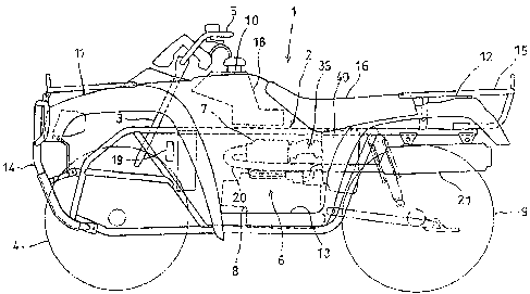
[023] Figure 1 is a. side elevational view of an all-texrain vehicle b.aving
an air-fuel delivery
apparatus mounted thereon according to a selected illustrative errnbodirr~ent
of the invention, in;
which an engine and related inteanal structure is shown. in phantozx~:
[024J Figure 2 is a top plan 'view of the vehicle of Figure 1.
[025] Figure 3 is a cross-sectional view of an upper portion of an engine and
air-fuel delivery
apparatus according to a fixst ezx~.bodiment hereo'F
[026] Figure 4 is a cross-sectional view of an upper portion of an engine and
aio-fuel delivery
apparatus according to a second ernbodiz~ezrt hereof
[027] Figw: a 5 is a perspective view of the air-fuel delivezy apparatus of
Figu~: a 4.
[028] Figure 6 is an exploded perspective view of the air-fuel delivery
apparatus of Figvice 5,
showing internal components thereof.
[029] Figure '7 is a schematic drawing, partially in cross-section, showing
internal structure of
CA 02481987 2004-09-15
tile air-fuel delivery apparatus of Figuxes 4-5_
[030J Figure 8 is a cross-sectional view of a fuel pressure regulator, wbzch.
is a coznpo~n.ent of
the air-fuel delivery apparatus of Figwes 4-5; and
[031] Figure 9 is a cross-sectional. view of an upper portion of an engine and
air-fuel delivery
apparatus according to a third embodiment hereof.
DETATX.~EJ<3 DESCRIPTIOl'd
[032] It should be undezstood that only structures considered necessary for
clarifying the
present invention are described herein. Other conventional structtu-es, and
those of ancillary and
auxiliary components of the system, are assumed to be known and understood by
those skilled in
the art.
[033] Referring to )~igul-es 1-3, a first illustrative embodiment of. the
pzesent invention will be
described.
[034j A. vehicle 1 having an au-fuel mixing and delivery apparatus for an
internal. coxnt~ustion
engine mounted thereon, according to a first embodiment of the invention, is a
four-~avheclEd
saddle-type all-terrain vehicle, and a general side view of the vehicle 1 is
shown in Fig. l, .
[035] In the vehicle 1, the lower end of a steering shaft 3, attached to the
front portion of a
vehicle body frame 2, is operative)y connected to left and right front whcEls
4, 4. A handlebar 5
is attached to the upper end of the steering shaft 3, arid a poweztrain unit
6, including an intezz~.al
combustion engine 7 and a transmission. $, is xnounted to the center of the
vehicle body frame 2.
Rear wheels 9, 9 ~u-e provided at the,rear portion of the vehicle L~ody :frame
2.
[036] All four of the vehicle's wheels 4, 9 are driven by the powertaain unit
6 via a foui-
wheel-drive system.
[03'7J A vehicle body shell 10 covers the vehicle frame 2 froze above. A pair
of front fendexs
6
CA 02481987 2004-09-15
1 l, 11 coves the front wheels 4, 4 from above, and rear fenders 12, 12 cover
the rear wheels 9, 9
fxozn above, respectively. Footrests are pro~~i.ded by runn.izzg boards 13
exrtending between the
front and rear fenders 11, 12.
[038] A front guard 14 is attached to the front end of the vehicle body frame
2. A rear luggage
carrier I 5 is attached to the rear portion thereof, and a saddle-type seat I
C~ is provided in front of
the rear luggage carrier 1 S, so as to extend over an area between the
powerdrain unit 5 arid the
rear wheels 9, as shown.
[039] A fuel tank 18 is supported by the veb.i.cle body frarxa.e 2 between the
steering shaft 3 and
the seat 16, and an oil cooler 19 is disposed below the fuel tank and in front
of the powertrain
unit 6.
[040 The engine 7 is a four-stroke-cycle single-cylinder internal combustion
engine, and is
positioned above the transmission 8 with the cylinder extending substantially
upright.
[041] An exhaust pipe 20 extending forward fiom a cylinder head 23 of the
internal
combustion engine 7 is curved left below the vehicle 'body and extends
rearwardly, and a muffler
21 is connected too the rear end of the exhaust pipe behind the left rear
wheel ~, as shown-
[042 An air cleaner 40 is located below the seat i6, and is connected to an
au~ inlet port 34 at
the back of the cylinder head 23 vza a throttle body 3S, which will be
described in detail referring
to Fig. 3.
[043 xhe iz~te~~al.,combustion, engine 7 includes a cylinder block 22 in which
a piston 25 is
slidably fitted, and a cylinder head 23 and a cylinder head cover 24
superimposed in sequence on
the cylinder block and joined integrally thereto.
[044 An ail-intake port 27 and a discharge port 28, respectively, are formed
as separate
passages in tl3.e cylinder head 23, and open into a combustion chambw 26
defined by a bottom
7
CA 02481987 2004-09-15
surface of the cylinder head 23. The air-intake port has an inlet oper~iz~g 34
formed in a side
surface of the cylinder head 23. The combustion chamber 26 faces toward the
top of the piston
25.
[045] The cylinder head 23 is p~°ovided with an. air-intake valve 29
and an exhaust valve 30 so
as to be capable o'.f open.ing and closing the respective openings therein,
and is also provided with
a valve motion drive mechanism 31 for driving the air-intake ~ ~~lve 29 and
the exhaust valve 30
on the cylinder head cover 24.
[046] The air-intake port 27 of the cylinder head 23 is provided with an
upstream inlet
opening 34 facing toward the rear of the engine, as noted, and the throttle
body 35 is connected
to the upstream inlet opening via a first connecting pipe 32; The air cleaner
40 is coxanected, via a
second connecting pipe 33, to the upstream opening of the Throttle body 35,
which extends
rearwardly from the cylinder head 23.
[04'7] ?he connecting pipe 33 interconnects the outlet openir.~g on the
filtered {downstrearx~)
side of the au~ cleaner 40, and the upstream. operxing of the throttle body
35_ The air cleaner 40 is
derned by an air cleaner element 42 in an air cleaner case 41.
[04g] In this manner, the inlet opening 34 for the air-intake port 27, the
throttle body 35, and
the air cleaner element 42 are arranged extending substantially linearly
rearwardly from the
cylinder head 23. The cylinder head 23 is provided extending substantialJ.y
upright on the internal
combustion engine 7 under the seat I6. The throttle body 35 and the air
cleaner. element 42
extend substantially linearly ~'ozn. the cylinder head 23 toward the rear of
the vehicle body, above
the cylinder block 22 of the internal. combustion engine 7.
[049] A fuel injector 37 is 1'axedly attached to the upper side of the
tllrattle body 35 desczibed
above, and the throttle body 35 has a hollow fuel inlet passage 43 formed
therein to allow fuel
CA 02481987 2004-09-15
from the fuel injector 37 to flow into the interior of the throttle body.
[O50] The fuel injector 37 is positioned above atlarottle plate 3G ofthe
throttle body 35, The
injector is attached obliquely relative to the direction of intake air flow
tlwough the thaottJ.e body
35, so as to be capable of injecting fuel toward the dovvn.st~~eam end of the
air-intake port 27.
[051 ] The main body of the internal combustion engine is positioned in front
of th.e .fuel
injectoi 3'7, anal the seat 16 covers the same from above, ~ shown in Figure
3.
[052] Therefore, the fuel injector 37 may be substantially shielded from water
or mud
splashing upwardly from the front of the vehicle 1 during tra~rel, in
particular, by the cylinder
head 23 and the head cover 4.
[053] In addition, the air-intake system components such as the throttle body
35 and the air
cleaner 40, wbach axe disposed behind the main body of the internal combustion
engine can also
be substantially protected from water or mud during normal use.
[054] In the practice of the present invention, the mounting position of the
fuel injector 37 is
not limited to the upper side of the throttle body 35, but may be the bottom,
the left side or the
right side, as long as it is on a side sur face of the throttle body :SS.
[055] Subsequently, another embodiment, in which a fuel pump 63 and a fuel
injector 37 are
both operatively attached to the throttle body 52, will be described herein
with reference to
Figures 5-6.
[056] The internal combustion engine 7, the air cleaner 40, and the fuel
injector 37, other than.
the thr. ottle body, arc the same in the second embodiment as those as
previously described in
connection with the first embodiment, and hence the same components are
represented by the
same reference numerals.
1057] ,A, ain-fuel mixing and delivery apparatus 50 in the second embodiment
hereof has a
9
CA 02481987 2004-09-15
stsvcture including the fuel injector 37 fitted tv the upper side of a
throttle body 52 having a
throttle plate S 1, and a fuel pump 63 assembled thereon above t:be fuel
injector 37.
[OS8] Refez~ing now to :Fig. 5 and 6, the throttle body 52 of the air-fuel
mixing and delivery
apparatus 50 includes first and second valve shaft supporting cases 53, 53
extending outwardly
in opposite directions thereon, for storing a valve drive mechanism and a
throttle position sensor.
The valve drive mechanism is provided for pivotally supporting and driving a
throttle shaft,
which supports the thr ottle plate 5 J. thereon.
[059] The air-fuel mixing and delivery apparatus SO also has an injection
valve mounting hole
54 forrrled therein on the upper poztion of tlxe throttle body 52, for
receiving the fuel injector 37.
[060] ~ cylindrical pump case 55, for suppozrting the fuel pump 63 therein, is
integrally
formed with the throttle body 52 at a position above the injection valve
mounting hole 54, so as
to be oriented substantially perpendicular to the throttle body 52.
[061 ] The center axis of the fuel injector 37 is oriented obliquely with
respect to the eentr al
axis of the throtti.e body 52, and a nozzle portion of the injector is
directed obliquely into the
throttle body 52, so that the du~ection of injection. is oriea~ted into the
air-intake port 27 at an
acute angle with respect to the center axis of the throttle body 52.
[062] Therefore, the fuel injector 37 injects a controlled amount of fuel into
the throttle body
for entry into the air-intake poet 27 and the combustion chamUer 26, based in
part on the rota~.y
speed of the engine and tb.e throttle plate opening position.
[063] The pump case SS is closed at one end of a cylinder body SSa by an end
wall SSb, The
other end of the pump case 55 is disposed adjacent the throttle body 52, and
is forzned with a
substantzal.ly rectangular opening 55c so as to protrude obliquely downwardly
in a substantially
rcctangulaa.~ shape.
CA 02481987 2004-09-15
[064] The end wall 55b is provided with a vacuum pipe 56 projecting outwardly
therefrom,
and the cylinder body 55a is provided with a fuel return pipe 5'7 projecting
obliquely upwwdly
fzoxz-~ the side wall thereof.
[065 The rectangular opening 55c is formed with a recess 55d therein, at a
position obliquely
downward of a ci~~cular hole of the cylinder body SSa, and a fuel feed path.
58 connected to the
fuel injector 37 is formed from the recess 55d toward the injection valve
mounting hole 54.
[066] The peripheral end surface of the opening including the recess 55d of
the rectangular
opening SSc is formed with a groove SSe extending peripherally therearoun:d,
and a sealing
gasket member 59 is fitted to the groove 55e.
[067J A fuel pump 63 fits inside of the cyli~ader body 55a of the purc-rp case
S5, as shown.
A fuel fi.J.ter 64, formed ofplastic resin, is attached to the fuel pump 63 on
the front end
in the direction of inseWion. The fuel pump 63 is provided wi.th~ a discharge
pipe 66 via a check
valve 65 at tla.e rear end thereof in the direction of insertion so ~~s to
project therefrom, and a
pressure regulator 70 is mounted at the midpoint of the discharge pipe 66.
[068J When inserting the fuel pump 63 into the cylinder Godly 55a of the pump
case 55, the
discharge pipe 66 and the pressure regulator 70 fit into the recess 55d inside
the rectangular
opening 55c of the puxxxp case 55, and the diseh~urge pipe 66 is 'fitted into
the fuel feed path 58
continuing to the fuel injector 37.
[069] Then, a substantially rectangular lid member 44 is fitted on the
rectangular openi~zg 55c
o:f the pump case 55, and the lid member 44 is secured to the pump case with.
bolts 61, as shown.
[070] The lid member 44 is farmed with an opening 45 thErein, and a power
distributing
connector 68, projecting from the fuel pump 63, fits through this opening, and
is exposed to the
outside through the opening 45.
11
CA 02481987 2004-09-15
(071 ] Since the fuel pump 63 and the pressure regulator 70 described above
are operatively
attached to the throttle body 52 to constitute the au~-fuel mixing and
delivery apparatus 50, the
length of piping required for transfewing high-pressure fuel from th.e fuel
pump 63 to the injector
37 can. be reduced significantly, thereby reducing the cost. T, he fuel
injection apparatus can be
compactly consolidated with this arrangement, and flexibility of layout of the
vehicle body may
be improved.
[072] Since the fuel pump 63 is adapted to be assembled on the upper side of
the au~-fuel
mixing and delivery apparatus 50 with the longitudinal axis thereof oriented
substantially
perpen.dicula.rly to the axis of the throttle body 52, the apparatus is
further downsized.
[073] A schematic drawing of the internal structure of the fuel feed
mechanism, from the fuel
pump 63 tc~ the fuel injector 3? in the appwatus 50 is shown in Fig. 7.
[074] The fuel pump 63 is integrated in a cylindrical housing 63a, and a
plurality of magnets
60a are provided along the inner peripheral surface of the cyliri,drical
housing 63a. Within the
cylindaical housing 63a, a coil 60d is wound around a core 60c formed
integrally with a
revolving shaft 60b, which is rotatably supported at both ends, so as to
constitute an inner rotor.
[075] A,z~ izx~peller 161 is integ; ally secured to one end of the revolving
shah 60b, and during
operation of the fuel pump, a current is distributed to the coil 60d whereby a
motor 60 is d~.~iven.
When the revolving shaft 60b is rotated with the impellw 161, fuel is
introduced from the fuel
tank 18 via a ~.el feed pipe (not shown), connected to the vacuuxn pipe 36,
and then fuel which
has been drawn into the cylindrical housing 63a via the filter 64 is
discharged to a fuel channel
62 at the other end of the rylindrical housing 63a.
[076] Fuel discharged into the fuel channel 62 is introduced from the fuel
lead-in port 7I a of
the presser a regulator 70 via the check valve 65, is introduced from the fuel
lead-out port 71b
12
CA 02481987 2004-09-15
into the fuel feed path 3 $ with the pzessure neguiated, and is fed to the
fuel injector 37 fi~om the
fuel feed path 38.
[077J When fuel in the fuel purlap 63 becomes overheated, such as during hot
weather, vapor
may be generated. However, fuel vapor moves upwardly in the fuel pump 63, and
is returned to
the fuei tank via the fuel return pipe 57, which i.s oriented obli.guely
upward from a fuel return
channel 163. and a retm.~n pipe, not shown.
[078J Fig. 8 shows a cross-sectional view of the pressure regulator 70.
[079J An upper case section 71 and a Iower case section 72 are each
substantially cup-shaped,
a~: a a~.ranged facing towaz-d one another, and are crimpingly connected to
de'~zie a space
therebetween hold a diaphragri7 74. The diaphragm 74 supports a valve body 73
between the
upper and louver case sections 7l, 72 so as to divide th.e internal space into
upper and lower
spaces.
[080J A, fuel lead-in port 71 a and a fuel lead-out port 71b (~'ee Fig. 7) are
foamed on the upper
case section 71, and a relief poet 72a is formed at the center of the
bottornwali of the lower case
?2.
[081] The valve body 73 is forxhed with an opening-and-cl.osin.g hole 73a at
the center thereof,
and the valve body 73 itself is urged toward the upper case 71 by a spring 75.
[082] Above the opening-and-closing hole 73a, there is formed a fitting hole
73b having a
larger diameter, and a fitting rod 74 projecting into the inteinalL space
fi~om. the upper case 71 is
positioned so as to be capable of being fitted into the fitting hole 73b.
[083J When the pressure of fuel. iatraduced into the upper case 71 is a
predetermined pressure
or lower, the fitting rod 74 is fitted into the fitting hole 73b of the valve
body 73, which is urged
by the spring 75, to close the opening-and-closing hole 73a, and fuel
introduced into the uppez
13
CA 02481987 2004-09-15
case 71 is l.ed out from the fuel lead-ort port 71b.
[08~] When the pressure of fuel introduced into the upper case 71 exceeds the
predc~tern~ined
pressure, the valve body 73 is moved toward the lower case 72 against the
spring 75, azzd then
the fitting rod 74 is pulled out froznth.e fitting hole 73b ofthe valve body
73 to open the opening-
and-closing hole 73a, and fuel introduced into the upper case '71 is
introduced into the lower case
72, so that it can be led out from the relief port 72a for adjusting the
pressure,
[085] In the aforementioned embodiment, the fuel pump 6s is operatively
attached to the
upper side of the air-fuel mixing and delivery apparatus S0. I:n contrast, an
example in which the
fuel pump is assembled to the lower side oftb.e throttle body will be shown in
Fig. 6.
(08Ci] A fuel injector 85 is assembled to the upper side of a throttle body 81
of a air-fuel
mixing and delivezy apparatus 80, and a fuel pump 86 is assembled to the lower
side of the
throttle body 81.
(087] , The fuel pump 86 is formed into a cylindrical shape which is the same
structure as the
fuel pump fi3 in th.e aforementioned embodiment, and is operatively attached
to the throttle body
81 in the direction orthogonal thereto. The fuel:puxnp S6 is provided with a
pressure regulator
together with the check valve_
(088] In the fuel injection apparatus of the present embodiment as well, the
fuel pump 86 and
the pressure regulator arc operatively attached to the au~fuel mixing and
delivery appa~-atus 80,
and the fuel pump 63 is assembled to th.e lower side of the air.-fuel mixing
and delivezy apparatus
80. Therefore, the fuel injection apparatus can be compactly consolidated to
be downsized, and
hence flexibility of layout of the vehicle body may be improved.
[489] Although the present invention has been described her ein with respect
to a number of
specific illustz~ative embodiments, the foregoing description is intended to
illustrate, rather than
14
CA 02481987 2004-09-15
to lizzzit the invention. Those skilled in the art will realize that 3nany
modifications o.f. the
preferred embodiment could be made 'which would be operable. All s~ich
modifications, which
ar a within the scope of the claims, are intended to be within the scope and
spirit of. the present
invention.