Note: Descriptions are shown in the official language in which they were submitted.
CA 02482156 2004-10-12
WO 03/092874 PCT/US03/11060
PRODUCT DISPENSER
FIELD OF THE INVENTION
The present invention relates to a product dispenser for
dispensing a product.
BACKGROUND OF THE INVENTION
Liquid products, such as liquid cleaning products, are used
throughout residential and commercial properties in a variety of
applications. Although liquid products have tremendous utility,
liquid products have a number of shortcomings. One primary
shortcoming is the bulkiness and weight of liquid products.
Packaged liquid products are usually either made relatively small
to keep the weight low, or made relatively large causing an
undesirable increase in product weight.
What is needed in the art is an improved method of
preparing a liquid product for use in residential, commercial, and
industrial applications.
SLTMMARY OF THE INVENTION
The present invention addresses some of the difficulties
and problems discussed above by the discovery of an improved
product dispenser and methods of using the product dispenser.
The product dispenser of the present invention may be used to
prepare a liquid solution, such as a cleaning or sanitizing
solution, having a desired concentration of active ingredients.
The liquid solution is prepared from a solid product, which
dissolves at a controlled rate to produce a desired amount of
liquid solution having a desired concentration.
Accordingly, the present invention is directed to a product
dispenser and a method of making the product dispenser. The
present invention is also directed to solid products, which may be
used in the product dispenser, and the combination of the product
dispenser with one or more solid products.
CA 02482156 2004-10-12
WO 03/092874 PCT/US03/11060
The present invention is further directed to a method of
making a liquid solution using the product dispenser. The
method provides a liquid solution having a desired concentration
of one or more active ingredients.
These and other features and advantages of the present
invention will become apparent after a review of the following
detailed description of the disclosed embodiments and the
appended claims.
BRIEF DESCRIPTION OF THE FIGURES
FIG. 1 depicts a frontal view of an exemplary dispenser of
the present invention;
FIG. 2 depicts a rear view of the exemplary dispenser
shown in FIG. 1;
FIG. 3 depicts a rear view of another exemplary dispenser
of the present invention;
FIG. 4 depicts the exemplary dispenser shown in FIG. 3 in
combination with a sink and faucet;
FIG. 5 depicts an exemplary product dispenser and solid
product, wherein a cavity of the product dispenser and the solid
product have similar cross-sectional configurations;
FIG. 6A depicts an exemplary solid product having
increased surface area; and
FIG. 6B depicts a view of the exemplary solid product of
FIG. 6A along line "C-C" shown in FIG. 6A.
DETAILED DESCRIPTION OF THE INVENTION
To promote an understanding of the principles of the
present invention, descriptions of specific embodiments of the
invention follow and specific language is used to describe the
specific embodiments. It will nevertheless be understood that no
limitation of the scope of the invention is intended by the use of
specific language. Alterations, further modifications, and such
further applications of the principles of the present invention
discussed are contemplated as would normally occur to one
ordinarily skilled in the art to which the invention pertains.
2
CA 02482156 2004-10-12
WO 03/092874 PCT/US03/11060
The present invention relates to a product dispenser for
forming a liquid "use" solution from a water and solid product
mixture. As used herein, the terms '°use solution" and "liquid use
solution" refer to an aqueous solution resulting from the
interaction of water and a solid product within a product
dispenser of the present invention. The present invention further
relates to solid products for use in the product dispenser, and
dispensing systems comprising the product dispenser and the
solid product. Desired use solutions may be prepared using the
dispensing systems of the present invention as described below.
I. Product Dispehse~
The present invention is directed to a product dispenser.
The product dispenser enables the interaction of water with one
or more water-dissolvable solid products. The product dispenser
may have any configuration, shape and size, which enable water
to come into contact with the one or more water-dissolvable solid
products. Although reference may be made to a particular size
and shape, it should be understood that the product dispenser of
the present invention is not limited in any way to a particular
design, size or shape.
The product dispenser of the present invention comprises a
number of components. In one embodiment, the product
dispenser of the present invention comprises (i) a housing having
a cavity configured and arranged to receive a solid product,
wherein the housing has a bottom, a top, and at least one side
defining the cavity; (ii) an inlet for inputting water into the
housing, wherein the inlet and the cavity are configured so as to
provide fluid flow between the inlet and the cavity; (iii) a support
member positioned within the cavity, wherein at least a portion of
the support member is positioned at a distance, d, above the
bottom of the housing; (iv) an outlet on a first side of the
housing; and (v) a drain hole on the bottom of the housing. Each
component of the product dispenser provides a given function so
as to produce a desired use solution having a desired
concentration of solid product therein.
3
CA 02482156 2004-10-12
WO 03/092874 PCT/US03/11060
The product dispenser of the present invention may be
positioned relative to a water source for supplying water to the
product dispenser and one or more containers for collecting the
use solution and any residual solution exiting the drain hole of
the product dispenser. In one embodiment, the product dispenser
may be attached to a surface, such as a wall, using any
conventional securing means including, but not limited to,
screws, nails, nuts/bolts, adhesives, or a combination thereof. In
another embodiment of the present invention, the product
dispenser may comprise a bracket for attaching the product
dispenser to a surface adjacent to or accessible to a water source.
The bracket may be an integral part of the housing (e.g., the
bracket and housing are one continuous molded part) or the
bracket may be a separate component, which is connected to the
housing. The bracket may be attached to a surface (and the
housing) using conventional securing means as described above,
or may be configured to temporarily mount onto the surface, such
as a partition in a two-compartment sink.
In one desired embodiment of the present invention, the
braclcet is an arm configured and arranged to engage a ledge of a
partitioned sink such that the housing extends into one
compartment of the partitioned sink, and the adjustable outlet and
the drain hole of the product dispenser empty into the
compartment. In a further desired embodiment of the present
invention, the bracket is configured to engage a rim of a bucket
(i.e., a mop bucket) or other portable container, which may be
used to collect a use solution. In yet a further desired
embodiment of the present invention, the bracket is configured so
that the product dispenser may be hung from a faucet or other
piping, which is connected to a water source. In each of the
above embodiments, the bracket may be an integral part of the
housing or may be a separate component, which is connected to
the housing via a mechanical device such as described above.
In other embodiments of the present invention, the size and
shape of the product dispenser may be designed to match a given
water source and/or a container for collecting the use solution.
For example, the product dispenser may have a circular shape and
4
CA 02482156 2004-10-12
WO 03/092874 PCT/US03/11060
size such that the product dispenser fits snugly onto an upper
surface of a mop bucket or other container. A handle may be
connected to the product dispenser for carrying the product
dispenser, placing the product dispenser onto the container (i.e.,
mop bucket), and for removing the product dispenser from the
container.
The outlet of the product dispenser may be a fixed (i.e., not
movable) component of the housing or may include an overflow
adjustment plate to control the water flow within the product
dispenser. For an application in which a known concentration of
use solution is desired and the product dispenser is only used for
the single application, a user may desire a product dispenser
having a fixed outlet. For an application in which the same
product dispenser is used to product multiple use solutions
having varying concentrations of solid product therein, a user
may desire a product dispenser having an adjustable outlet. The
overflow adjustment plate may be positioned to move vertically
along a track in a side wall of the housing to control the height of
the water in the product dispenser. As discussed below, the
overflow adjustment plate may be one way to control the
concentration of solid product in the resulting use solution.
The product dispenser of the present invention may also
comprise one or more partitions within the housing. One or more
partitions within the housing may be used to control water flow
through the product dispenser. In one embodiment, the product
dispenser comprises a partition positioned vertically within the
housing, wherein the partition separates a cavity of the product
dispenser from a water inlet of the product dispenser. In this
embodiment, water flows from the inlet into the cavity of the
housing by passing beneath a lower edge of the partition. A
controlled flow of water is brought into contact with one or more
pieces of solid product positioned on the support member.
The support member may have a solid continuous
structure, such as a metal foil or plastic film, or may have a
discontinuous, permeable structure, such as a mesh or screen
formed from materials including, but not limited to, metals,
plastics, and combinations thereof. In one embodiment of the
5
CA 02482156 2004-10-12
WO 03/092874 PCT/US03/11060
present invention, the support member comprises a continuous
structure in a horizontal plane within the cavity of the product
dispenser, wherein the upper surface area of the support member
is less than the surface area of the horizontal plane such that
' water may flow through the horizontal plane from below the
continuous structure to contact the water-dispersible product
positioned on the continuous structure. It should be noted that
the support member may have a configuration other than one
which is within a single horizontal plane within a cavity of the
product dispenser. For example, the support member may have a
V-shape, U-shape, W-shape or any other configuration as long as
the support member is capable of supporting a water-dispersible
product within the product dispenser.
In a further embodiment of the present invention, the
support member comprises a permeable structure in a horizontal
plane within the cavity of the product dispenser, wherein the
upper surface area of the support member is less than or equal to
the surface area of the horizontal plane such that water may flow
through or around the support member from below the permeable
structure to contact the water-dispersible product positioned on
the support member. As discussed above, the permeable support
member may have a configuration other than one which is within
a single horizontal plane within a cavity of the product dispenser.
For example, the permeable support member may have any of the
configurations described above (i.e., V-shape, U-shape, W-shape,
or other shape).
A portion of the support member may be positioned at a
distance, d, above the bottom of the housing. For support
members having a V-shape, U-shape, or W-shape as described
above, the lower portion of the support member may actually rest
on an upper surface of the bottom of the housing. In other
embodiments, the lower portion of the support member having a
V-shape, U-shape, or W-shape may be at a distance, d, above the
bottom of the housing, while an upper portion of the support
member is positioned at a distance, (d + t), above the bottom of
the housing, wherein t represents the thickness of the support
member.
6
CA 02482156 2004-10-12
WO 03/092874 PCT/US03/11060
The product dispenser of the present invention may further
comprise one or more coverings along the top of the housing. A
single covering may be used to cover the cavity and/or the inlet
of the housing. Desirably, a covering is used to cover the cavity
of the housing to protect any solid product in the cavity from
accidental exposure to liquids, such as water. In one embodiment
of the present invention, a covering is used to cover the cavity of
the housing, wherein the covering expands an area having a
perimeter outlined by a partition and the at least one side of the
housing. Each of the one or more coverings may be separate
from and removable from the product dispenser or may be
attached to the product dispenser using any conventional method
of attaching. In one embodiment, a hinge is used to attach a
covering over the cavity of the product dispenser. Further, a
portion of the covering may form a bracket (as described above),
which may be used to position the product dispenser relative to a
water source and/or collection container as described above.
The product dispenser of the present invention may be
formed from any material having structural integrity and being
unreactive to water and solid product. Suitable materials for
forming the product dispenser include, but are not limited to,
plastics, glass, ceramics, metal or any combination thereof.
Desirably, the product dispenser comprises a clear or transparent
plastic cover material, which allows a visual inspection of any
solid product in the cavity. In one embodiment of the present
invention, at least a portion of the product dispenser comprises a
transparent material to allow a visual inspection of one or more
portions of the product dispenser, desirably, at least the interior
of the cavity and any solid product therein.
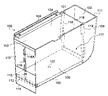
Exemplary product dispensers of the present invention are
shown in FIGS. 1-4. As shown in FIGS. 1-3, exemplary product
dispenser 100 includes top 101 with water inlet 102 and cover
103. Water inlet 102 is proximate a right side 111 of product
dispenser 100, and cover 103 includes a hinge 104 operatively
connected to dispenser 100 proximate the juncture of top 101 and
rear side 109. Cover 103 covers an opening of top 101 into
cavity 117 of dispenser 100, but does not cover inlet 102. In
7
CA 02482156 2004-10-12
WO 03/092874 PCT/US03/11060
other words, cover 103 extends across top 101 but terminates
along partition 118 where inlet 102 begins. In this exemplary
embodiment, inlet 102 remains open; however, it should be
understood that cover 103 may also extend over inlet 102 or a
separate cover (not shown) may be used to cover inlet 102 if so
desired.
As shown in FIG. 1, cavity 117 is defined by front side
108, left side 112, rear side 109, partition 118, and bottom 105 of
dispenser 100. Partition 118 divides dispenser 100 into inlet 102
and cavity 117, but partition 118 does not extend all the way to
the bottom 105. A space of approximately 1.3 cm. (0.5 in.) in
height is provided between the bottom edge of partition 118 and
bottom 105. Water entering inlet 102 enters cavity 117 between
the bottom edge of partition 118 and bottom 105 of dispenser
100. Partition 118 slides into slots 119 located vertically along
front side 108 and rear side 109 of dispenser 100. Partition 118
may be temporarily or permanently attached to slots 119 or may
fit snugly within slots 119 (without a separate attachment means,
such as an adhesive) to prevent water from passing into cavity
117 along the vertical edges of partition 118.
On the left side 112 of dispenser 100, there is an adjustable
overflow outlet 113 and a track 116 having a slot 116a opposite
inlet 102. Outlet 113 is an open area within left side 112 of
dispenser 100. Track 116 is a rectangular bar extending from
bottom 105 to top 101 proximate the middle of left side 112, and
slot 116a runs vertically along track 116. An overflow
adjustment plate 114 is vertically slidable along track 116 and is
secured in place by securing member 115, such as a wing nut or
other securing means known in the art. Overflow adjustment
plate 114 acts as a partial side to close a bottom portion of outlet
113 and is vertically adjustable to control the dwell time of water
solution within product dispenser 100. The higher the height of
overflow adjustment plate 114 along left side 112 of dispenser
100, the greater the dwell time and also the greater the degree of
contact between the water and solid product (not shown) within
cavity 117. The increased dwell time and exposure between the
water and the solid product results in a higher concentration of
8
CA 02482156 2004-10-12
WO 03/092874 PCT/US03/11060
the solid product, which dissolves into the use solution.
Conversely, the lower the height of overflow adjustment plate
114 along the left side 112 of dispenser 100, the shorter the dwell
time and contact time between the water and the solid product,
thereby resulting in a lower concentration of solid product
dissolved into the use solution. Use solution above overflow
adjustment plate 114 will flow out of outlet 113 while water
and/or use solution below overflow adjustment plate 114 will
flow out of drain hole 107. Although outlet 113 is located on the
left side 112 in this exemplary embodiment, it should be noted
that outlet 113 may be located on any of sides 108, 109 or 112.
(Further, as described above, the dimensions of outlet 113 can
also be fixed in some embodiments of the present invention.)
A product support member 106, such as a foil, film or
screen, may be placed within cavity 117 such that at least a
portion of support member 106 is above bottom 105 of dispenser
100. A solid product (not shown) is placed on top of product
support member 106 to prevent the solid product from resting
directly on the bottom 105, which prevents the solid product from
dissolving when product dispenser 100 is not in use. Drain hole
107 is located in the bottom 105 to provide an outlet for excess
water remaining in the bottom 105 of product dispenser 100
when product dispenser 100 is not in use. Therefore, although a
small amount of water may remain, product dispenser 100 is
mostly empty of water when not in use and product support
member 106 prevents any remaining water from contacting the
solid product. Drain hole 107 may vary in size and dimensions,
but is typically smaller than outlet 113 to insure some degree of
accumulation within product dispenser 100.
In one embodiment of the present invention, drain hole 107
may have an adjustable size to further control the amount of
water exiting drain hole 107. The size of drain hole 107 may be
adjusted similarly to the overflow outlet 113 as described above
or may be adjusted by any other mechanism.
As shown in FIGS. 2-4, a mounting bracket 110 or 110'
may be attached to product dispenser 100 proximate the rear side
109. Mounting bracket 110 or 110' may be an arm configured
9
CA 02482156 2004-10-12
WO 03/092874 PCT/US03/11060
and arranged to engage a partition or ledge 122 of a sink 120, so
that product dispenser 100 extends into compartment 123 of the
sink 120, and outlet 113 and drain hole 107 empty into
compartment 123. Mounting bracket 110 is shown as a flat
rectangular member extending outward from and parallel with the
rear side 109 and approximately 0.64 cm. (0.25 in.) therefrom to
provide a gap between bracket 110 and rear side 109. this 0.64
cm. (0.25 in.) gap allows the partition or ledge 122 of sink 120 to
slide within the gap for quick and easy installation of product
dispenser 100. Mounting bracket 110' is similar to mounting
bracket 110 but does not extend all the way to the bottom of rear
side 109. It should be noted that the mounting bracket may be
any length and configuration sufficient to engage a mounting
surface. In addition, screws or other securing means known in
the art may be used with the mounting bracket to temporarily or
permanently secure product dispenser 100 as desired. (Further, a
mounting bracket may be an integral part of the housing itself or
a covering over a portion of the housing as described above.)
If dispenser 100 is used with a sink, such as sink 120
shown in FIG. 4, inlet 102 is placed proximate faucet 121. A
natural air gap is provided by the distance between faucet 121
and inlet 102. Sink 120 includes a partition or ledge 122 dividing
sinlc 120 into compartments 123. Product dispenser 100 is placed
onto partition 122 to dispense product into one of the
compartments 123. Although product dispenser 100 as shown in
FIG. 4 is used with sink faucet 121, other water sources may be
used to dispense a solid product into a container (i.e., such as a
sink) included, but not limited to, a mop bucket, a laundry
machine or a pool.
As discussed above, product dispenser 100 may have a size
and shape so that the product dispenser matches a given water
source and/or a container for collecting the use solution. In one
desired embodiment of the present invention, the product
dispenser has a rectangular shape as shown in FIGS. 1-4;
however, it should be understood that other shapes are within the
scope of the present invention. Suitable shapes include, but are
not limited to, a circular shape, a square shape, a triangular shape,
CA 02482156 2004-10-12
WO 03/092874 PCT/US03/11060
a star shape, an arrow shape, a rhombus shape, a trapezoid shape,
etc. Desirably, the product dispenser has dimensions as follows:
an overall height ranging from about 7.6 cm (3.0 inches) to about
45.7 cm (18.0 inches); an overall length (as used herein, the
"length" is the dimension parallel with rear side 109 in FIG. 1)
ranging from about 15.2 cm (6.0 inches) to about 61.0 cm (24.0
inches); an overall width ranging from about 5.1 cm (2.0 inches)
to about 3 0.5 cm ( 12.0 inches); a cavity length ranging from
about 10.2 cm (4.0 inches) to about 55.9 cm (22.0 inches); a
height of the gap under partition 118 ranging from greater than 0
to about 5.1 cm (2.0 inches); a height of an upper edge of
overflow plate 114 (i.e., the distance from bottom 105 to an upper
edge of overflow plate 114) ranging from about 5.1 cm (2.0
inches) to about 40.6 cm (16.0 inches); and a height of at least a
portion of product support member 106 above bottom 105
ranging from greater than 0 to about 40.6 cm ( 16.0 inches).
In one embodiment of the present invention, the product
dispenser comprises a cavity, wherein the cavity has a cross-
sectional configuration, which matches a cross-sectional
configuration of the solid product to be used in the product
dispenser. In this embodiment, the solid product fits into the
cavity of the product dispenser in such a way that a user cannot
incorrectly input the solid product into the cavity of the product
dispenser without altering the configuration of the solid product.
Suitable cavity/solid product cross-sectional configurations for
use in this embodiment of the present invention include, but are
not limited to, a star-like cross-sectional configuration, an arrow
cross-sectional configuration, and a diamond cross-sectional
configuration. Desirably, the cavity/solid product cross-sectional
configuration is an arrow cross-sectional configuration.
An exemplary product dispenser/solid product system,
wherein the cavity and of the product dispenser and the solid
product have a similar cross-sectional configuration, is shown in
FIG. 5. Product dispenser 500 comprises a cavity 501, a water
a 35 inlet 502, a drain hole 503, and an outlet 504 in side wall 505.
Product dispenser 500 may further comprise other components as
described above; however, such additional components are not
11
CA 02482156 2004-10-12
WO 03/092874 PCT/US03/11060
shown in FIG. 5 in order to clearly depict the relationship
between cavity 501 and solid product 506. As shown in FIG. 5,
both cavity 501 and solid product 506 have an arrow-like cross-
sectional configuration. Such a cross-sectional configuration
system offers a user only one method of inputting solid product
506 into cavity 501 without altering the shape of solid product
506.
Although it is not clear from FIG. 5, it is desirable for solid
product 506 to have dimensions slightly smaller than the
dimensions of cavity 501 so that solid product 506 slides easily
into cavity 501. Typically, solid product 506 and cavity 501 have
dimensions such that a gap is formed between an outer edge of
solid product 506 and a surface of cavity 501. Desirably, the gap
has an average width of from about 0.3 cm. (0.125 in.) to about
1.3 cm. (0.5 in.), more desirably, from about 0.3 cm. (0.125 in.)
to about 0.6 cm. (0.25 in.); however, the gap may have an
average width outside of these desired ranges.
Product dispenser 100 accurately dispenses cleaning and
sanitizing products using a low cost and easy to install product
dispenser. The product dispenser is ideal for three-compartment
sinks commonly used in restaurants, but many other applications
are also possible. The product dispenser is readily mountable to a
variety of surfaces such as a sink, a wall, or a laundry machine.
Other uses and applications where dispensing of a solid product
is desired are also possible with the present invention, and the
product dispenser could be used with a variety of containers. In
one embodiment, a conduit (not shown) may be attached to outlet
113 and a conduit (not shown) may be attached to drain hole 107
to direct the use solution into a container if there is a distance
between the water source (such as faucet 121) and the container.
Because of the easy installation and the easy use of the product
dispenser, plumbing regulatory issues are reduced or even
eliminated and installation costs are minimal since the end
customer can readily install the product dispenser. In addition,
since there are no moving parts or electrical components in
product dispenser 100, service costs are also minimal.
12
CA 02482156 2004-10-12
WO 03/092874 PCT/US03/11060
II. ~S'olid Product
The present invention is also directed to solid products for
use in the above-described product dispensers. The solid
products comprise one or more water-dissolvable components,
which are formed into a desired shape having a desired size. The
solid products may have any shape or size suitable for use in the
product dispensers. For example, the solid products may be in
the form of pellets, beads or powders having a size such that
hundreds of pieces of solid product fill a given product dispenser.
The pellets, beads or powders may be shaped into larger pieces of
solid product such that only one or a dozen pieces of solid
product fit within a given product dispenser. Typically, the solid
products have a rectangular, square, triangular, circular, arrow-
like, rod-like, or star-lilce shape as described above. Desirably,
the solid products have a rectangular, square, or arrow-like shape.
In one desired embodiment of the present invention, the
solid product has a size, which enables one or more pieces of
solid product to be placed within the cavity of the product
dispenser, wherein each piece of solid product has a
configuration, which increases the surface area of the piece of
solid product. For example, a solid product may have a
rectangular or square shape, and also have one or more holes
through the rectangular or square shape in a direction parallel or
perpendicular to a horizontal axis of the solid product. Other
solid product configurations may include fins or slots within the
product to increase the surface area of the product.
An exemplary solid product having increased surface area
is shown in FIGS. 6A and 6B. As shown in FIGS. 6A and 6B,
solid product 600 has three rows of holes 601, 602, and 603
extending through solid product 600 from end 604 to opposite
end 605. The holes result in an increased surface area for
possible contact with water flowing through the cavity of the
product dispenser. As shown in FIG. 6B, the three rows of holes
comprise an upper row 601 having three holes of similar diameter
and a lower row 603 having three holes of similar diameter to the
hole in upper row 601. The holes within middle row 602 have
similar diameters, which are smaller than the hole diameters of
13
CA 02482156 2004-10-12
WO 03/092874 PCT/US03/11060
the holes in rows 601 and 603. This particular configuration of
holes enables the formation of "pillars" in solid product 600 at
locations 607 as solid product 600 dissolves from lower surface
608. As solid product 600 dissolves from lower surface 608,
holes in row 603 become exposed to water, and loose their
circular shape. At a point where an upper portion of the holes in
row 603 and a lower portion of the holes in row 602 are
contacted by water, pillars are formed at locations 607. Likewise,
at a point where an upper portion of the holes in row 602 and a
lower portion of the holes in row 601 are contacted by water,
pillars are formed at locations 607.
It should be noted that the number of holes, the shape of
holes, the size of holes, the number of rows of holes, the
combination of different hole sizes, and the combination of hole
shapes may be varied as desired in the solid products of the
present invention. In some solid products, a higher density of
smaller holes may be desired, while other solid products may
advantageously have a lower density of smaller holes or larger
holes.
In one desired embodiment of the present invention, the
solid product has a hole configuration as shown in FIGS. 6A and
6B. The solid product may have any shape, but desirably, has a
rectangular, diamond or arrow shape. In this embodiment, the
solid product has a height of about 5.1 cm. (2.0 in.), a width of
about 7.6 cm. (3.0 in.), a depth of about 17.8 cm. (7.0 in.), three
rows of holes as shown in FIGS. 6A and 6B, wherein each hole in
the upper row of holes and the lower row of holes (i.e., total of
six holes) have a hole diameter of about 1.3 cm. (0.5 in.), and
each hole in the middle row of holes (i.e., total of two holes) have
a hole diameter of about 0.6 cm. (0.25 in.). Desirably, the solid
product has the above-described dimensions and an arrow shape
for use with a product dispenser having a coordinated arrow-
shaped cavity.
The solid products may comprise one or more water
dissolvable components. Suitable water-dissolvable components
include, but are not limited to, components selected from
detergents, surfactants, sanitizers, pest control agents, or a
14
CA 02482156 2004-10-12
WO 03/092874 PCT/US03/11060
combination thereof. Suitable solid products include, but are not
limited to, products disclosed in U.S. Patent Application Serial
No. 09/282,001, filed on March 29, 1999 entitled "SOLID POT
AND PAN DETERGENT" and assigned to Ecolab Inc. (St. Paul,
MN), the entire contents of which are herein incorporated by
reference. Desirably, the solid product comprises a pot and pan
type detergent, such as the MAGFUSION Product, available from
Ecolab Inc. (St. Paul, MN).
Solid products having an increased surface area may be
formed from any of the water-dissolvable components described
above. In addition, solid products having an increased surface
area may be formed from commercially available solid products
including, but not limited to, the MAGFUSION Product from
Ecolab Inc. (St. Paul, MN).
III. Dispensing Systems
The present invention is further directed to dispensing
systems comprising the above-described product dispensers and
solid products. In one embodiment of the present invention, the
dispensing system comprises (i) a product dispenser comprising a
housing having a cavity configured and arranged to receive a
solid product, the housing having a bottom, a top, and at least one
side defining the cavity; an inlet for inputting water into the
housing, wherein the inlet and cavity are configured to provide
fluid flow between the inlet and the cavity; a support member
positioned within the cavity, wherein at least a portion of the
support member is positioned at a distance, d, above the bottom
of the housing; an outlet on a first side of the housing; and a drain
hole on the bottom of the housing; and (ii) a solid product
positioned on the support member.
In one desired embodiment of the present invention, the
dispensing system comprises (i) a product dispenser having a
cavity, and (ii) a solid product, wherein the cavity and solid
product have substantially similar cross-sectional configurations.
In this embodiment, the solid product fits into the cavity in such a
way that a user instantaneously knows how to input the solid
product. Desirably, the cavity and the solid product have a cross-
CA 02482156 2004-10-12
WO 03/092874 PCT/US03/11060
sectional configuration in the shape of an arrow. Further, the
solid product desirably has an increased surface area resulting
from one or more holes through the solid product as described
above and depicted in FIGS. 6A and 6B.
The dispensing system may be used in a variety of
applications where a use solution is desired. Typically, the
dispensing system is positioned at a location within a residential,
colnlnercial or industrial property for easy access for a user. ~ne
or more pieces of solid product are positioned within the product
dispenser and replaced as needed. In some applications, the solid
product is used for a single batch operation. In other
applications, solid product is used on more of a continuous basis,
such that additional solid product is placed into the product
dispenser on a regular basis.
When solid product is placed in the product dispenser, it is
desirable for the solid product to have a total volume equal to or
less than a cavity volume bordered by the top of the housing, the
support member, and the at least one side of the housing. One or
more pieces of solid product may be used to fill the cavity
volume. Desirably, the one or more pieces of solid product may
be stacked one on top of the other to fill the cavity volume, and
also provide a consistent surface area of solid product within a
horizontal plane of solid product as one moves along a vertical
direction within the product dispenser cavity. Such a
configuration enables a consistent dispersion of solid product
into the water, which contacts the solid product.
As discussed above, the product dispenser may have any
dimensions necessary for a given application. For more
continuous applications wherein an amount of solid product is
used on a continuous basis, the dimensions of the product
dispenser may be selected such that the cavity has relatively
small cross-sectional dimensions when compared to the height of
the cavity. In this embodiment, numerous solid products may be
stacked on top of one another.
The dispensing rate of the product dispensing system and
the concentration of the resulting use solution are determined by
a number of factors including, but not limited to, the water flow
16
CA 02482156 2004-10-12
WO 03/092874 PCT/US03/11060
rate, the water temperature, the dissolving rate of the solid
product, the surface area of the solid product exposed to the
water, and the contact time between the water and the solid
product. By varying one or more of the above variables, a
desired dispensing rate and use solution concentration is
obtained.
Ih Methods of Making a Liquid Use Solution
The present invention is further directed to a method of
making a liquid use solution comprising: (i) positioning a product
dispenser, a water source, and a container relative to one another,
wherein the product dispenser comprises: (a) a housing having a
cavity configured and arranged to receive a solid product, the
housing having a bottom, a top, and at least one side defining the
cavity; (b) an inlet for inputting water into the housing, wherein
the inlet and the cavity are configured so as to provide fluid flow
between the inlet and the cavity; (c) a support member positioned
within the cavity, wherein at least a portion of the support
member is positioned at a distance, d, above the bottom of the
housing; (d) an outlet on a first side of the housing; and (e) a
drain hole on the bottom of the housing; (ii) placing one or more
pieces of solid product on the support member of the product
dispenser; (iii) passing water from the water source through the
product dispenser such that the water comes into contact with the
solid product and exits the outlet on the first side of the housing
as a use solution; and (iv) collecting the use solution in the
container.
The method may be practiced using a variety of water
sources including, but not limited to, a faucet, a water hose, a
water valve, a water pump, or a bucket of water. The product
dispenser may be designed to couple directly or indirectly to one
or more of the above-mentioned water sources. Attachment
means and/or brackets, such as those described above, may be
use to temporarily or permanently position the product dispenser
relative to the water source.
The method may produce a use solution for collection in a
variety of container types. Suitable containers for collecting the
17
CA 02482156 2004-10-12
WO 03/092874 PCT/US03/11060
use solution include, but are not limited to, a sink, a bucket, a
laundry machine, a sauna, or a pool. In one desired embodiment
of the present invention, the method produces a use solution,
wherein the water source is a faucet, and the container is a sink
having a sink partition dividing the sink into at least two
compartments.
The method of the present invention may be further
described with reference to FIGS. 1-4. In an exemplary operation
(shown in FIG. 4), product dispenser 100 is placed proximate
faucet 121 so that water enters inlet 102. Product dispenser 100
is a flood-type dispenser. Water-dispersible solid product is
dispensed concurrently as sink compartment 123 is filled with
water and/or use solution. Water fills cavity 117 faster than
water and/or use solution exits drain hole 107. Therefore, the
flooding of cavity 117 allows water to contact the solid product,
thereby dissolving a portion of the solid product to create the use
solution. In this exemplary embodiment, outlet 113 and drain
hole 107 each independently empty into sink compartment 123;
however, it should be noted that either of outlet 113 and drain
hole 107 may be emptied into another type of container, such as
bucket (not shown). If product dispenser 100 empties into sink
compartment 123, mounting bracket 110 or 110' may be placed
about the sink partition or ledge 122. If the product dispenser
empties into a bucket, mounting bracket 110 or 110' may be
placed on a vertically oriented surface proximate the bucket or on
an edge of the bucket. Alternatively, mounting bracket 110 or
110' may be modified for attaching to a wall. Again, a conduit
may be used to carry the use solution from product dispenser 100
into a container or a bucket. .
The solid product is dissolved during the dispensing cycle
when water enters inlet 102, and adjustable plate 114 is adjusted
so that water comes into contact with the solid product being
dispensed. The solid product is placed on support member 106,
and water flows from faucet 121 into inlet 102 and then into
cavity 117 from the bottom 105. Partition 118 ensures that water
enters cavity 117 from the bottom 105 of product dispenser 100.
As water floods cavity 117 from the bottom 105 of product
18
CA 02482156 2004-10-12
WO 03/092874 PCT/US03/11060
dispenser 100, the water rises above support member 106 to
contact the solid product. A portion of the solid product
dissolves into the water to form a use solution. The use solution
exits product dispenser 100 through outlet 113 and drain hole
107. Overflow adjustment plate 114, when present, may slide
vertically along track 116 and may be secured with securing
member 115 to allow a desired amount of use solution to be
dispensed. The longer the solid product is exposed to water, the
more solid product will dissolve to create the use solution and the
converse is also true. Therefore, the higher overflow plate 114,
the longer the water will contact the solid product and vice versa.
To stop the dissolving process between uses, drain hole
107 in the bottom 105 of product dispenser 100 allows most of
the water to exit product dispenser 100. This allows the solid
product to dry between dispensing cycles to ensure that a desired
concentration is dispensed each time. Although drain hole 107 is
always open, water accumulates within cavity 117 faster than
water drains through drain hole 107, thereby allowing cavity 117
to flood with water. As described above, the rate of
accumulation may be varied by adjusting the size of drain hole
107, adjusting the position of overflow adjustment plate 114, or
both.
When used with sink 120 (see FIG. 4), installation of
product dispenser 100 is quick and easy because mounting
bracket 110 or 110' may be placed about sinlc partition 122 such
that inlet 102 is positioned underneath faucet 121 whenever
dispensing of the solid product is desired. After the solid product
has been dispensed, product dispenser 100 can be removed from
sink partition 122 or simply positioned out of the way of faucet
121. A restrictor (not shown) could also be used to prevent
removal of product dispenser 100 from sink 120 to insure that the
use solution flows into the proper compartment during the
dispensing cycle.
The method of the present invention may be used to
prepare a use solution having a desired concentration of solid
product within an aqueous solution. A number of variable may
be considered to obtain a desired use solution concentration
19
CA 02482156 2004-10-12
WO 03/092874 PCT/US03/11060
including, but not limited to, the water flow rate, the dwell time
of the water within the cavity of the product dispenser, the
contact time between the water and the solid product, the water
temperature, the dissolving rate of the solid product, the chemical
formulation of the solid product, the shape of the solid product,
the amount of surface area of the solid product, the height of the
adjustable outlet, and the water flow rate out of the drain hole.
By adjusting one or more of the above variables, a desired use
solution concentration may be obtained.
Water flow rate is one important consideration in obtaining
a desired use solution concentration. A controlled water flow is
desirable to control the contact between the water and the solid
product. In the exemplary embodiments shown in FIGS. 1-4, a
partition is used to control the influx of water from inlet 102 into
cavity 117. This particular design forces the water flow to turn a
corner and come up under the solid product. It should be
understood that other designs may be used to control water flow
and the method of contacting the solid product. One possible
alternative is to have the water fall directly on the solid product
or by removing some or all of partition 118. One further possible
alternative is to incorporate slots or holes at one or more
locations within partition 118 to direct water toward the solid
product in a controlled manner. The water flow and contact time
may also be adjusted by changing the size of the holes in the
product support member 106. Further, water flow may be
controlled by increasing or decreasing the size of the product
dispenser and any of its components. In addition, the water flow
may be controlled by restricting the supply of water to the
product dispenser though the use of valves and/or flow regulator
devices.
Water temperature changes may also effect the
concentration of the use solution. Some water-dissolvable
components in the solid product may have a dissolution rate,
which is temperature dependent. If desired, a water temperature
process control device may be used to monitor the water
temperature and adjust water flow rate as the temperature
changes. For example, a water flow compensating device may be
CA 02482156 2004-10-12
WO 03/092874 PCT/US03/11060
use, wherein the device would cause more water to bypass the
solid product (i.e., passing through drain hole 107) as the
temperature increased. Other devices may be used to heat the
water prior to or after entering the product dispenser.
The contact time between the water and the solid product is
a key factor in the method of preparing a use solution. If the
water flows past the solid product too fast, the contact time may
be insufficient to dissolve the solid product. To compensate for
this, the product dispenser is designed to increase the level of
solid product exposure to the water automatically as the water
flow rate increases. This is accomplished by managing the
geometry of the outlet opening. As the water flow rate increases,
the outlet opening restricts the water from exiting the product
dispenser. This restriction causes the water to back up in the
product dispenser. As the water baclcs up, the water level in the
product dispenser rises. The higher water level results in more of
the solid product being exposed to the water, increasing the
dispensing rate of the solid product. Therefore, there is a built in
compensation for higher water flow rates that allows the product
dispenser to maintain more accurate dispensing rates at different
water flow rates.
The chemical formulation and product design of the solid
product also affect the concentration of the use solution. The
dissolving rate of the solid product may be affected by one or
more of the following factors: the formulation of the solid
product, the shape of the solid product, the density of the solid
product, and the method of exposing the solid product to water.
Desirably, a homogeneous solid product of a known dissolving
rate is used to produce a consistent product dispensing rate.
The surface area of the solid product exposed to the water
affects the dispensing rate because contact with the water causes
the solid product to dissolve. Therefore, for a given water level
in the product dispenser, as the solid product size increases, the
surface area increases and the dispensing rate increases.
I3owever, the surface area may be increased without increasing
the overall size of the solid product as described above. In an
effort to minimize the size of the solid product and the product
21
CA 02482156 2004-10-12
WO 03/092874 PCT/US03/11060
dispenser, holes may be drilled or molded into the solid product
shape to increase the surface area. Desirably, holes are formed in
the solid product during an extrusion process. The water then
comes into contact with the outer surfaces of the solid product as
well as the inner surfaces of the holes in the solid product. The
increased surface area of the solid product exposed to water
increase the dispensing rate of the solid product. Fins or grooves
may also be used as a means to increase the solid product surface
area without changing the overall size of the solid product shape.
As the product is dispensed the surface area of the product
may change. As the surface area changes, the amount of solid
product dissolved by the water also changes and therefore the
dispensing rate changes. In order to control the dispensing rate
as accurately as possible, the change in surface area is desirably
minimized throughout the method of malting a use solution.
Several methods may be used to accomplish this. One method is
to strategically produce a solid product having holes therein such
that as the solid product dissolves, the surface area exposed to
water stays substantially the same. For example, when the
outside of a solid product shape dissolves, the surface area is
reduced; however, the inside of the holes are also dissolving so
the holes are getting bigger and therefore the surface area of the
holes is increased. It is possible to balance the change in surface
areas (i.e., decreasing outer surface area and increasing hole
surface area) to minimize the overall change in dispensing rate.
One example of such a balance is described above and depicted
in FIGS. 6A and 6B.
A second method of controlling the change in surface area
of the solid product is to utilize a finned or star-shaped solid
product. As the fins dissolve, the surface area change is
minimized because the fin length does not change.
A third method is to reduce the amount of solid product
exposed to the water. In one embodiment of the present
invention, a long rod-shaped solid product may be used. In this
embodiment, as the solid product dissolves from the bottom, the
rod forms a cone on the bottom. The cone has a different surface
area than the original rod. The cone is longer as the height of the
22
CA 02482156 2004-10-12
WO 03/092874 PCT/US03/11060
water on the rod is increased. By reducing the height of the water
in relation to the rod, the cone that forms may be minimized.
Consequently, the change in surface area of the solid product may
be minimized.
Another area of consideration when looking at the solid
product shape is how the solid product falls when it dissolves. In
order for the dispensing rate to be as consistent as possible during
operation, the surface area of the solid product exposed to water
desirably stay substantially the same as the solid product moves
from an old piece of solid product to a new piece of solid product
within the product dispenser. Desirably, the pieces of solid
product are stacked in the product dispenser so that a user has a
constant supply of solid product available for dispensing. As the
solid product dissolves, the solid product shape and the product
dispenser enable the operation to hove smoothly from one piece
of solid product to the next. The shape of the solid product is
desirably such that the remains of the lower solid product shape
does not inhibit the upper solid product shape from falling into ,
place for contact with water. Using holes in the solid product
shape is one method of assuring that the upper solid product
shape falls into place (such as described above and depicted in
FIGS. 6A and 6B). The holes may be positioned in the solid
product shape to allow the shape to have weak spots, which
collapse and allow the upper solid product to move into a
position, which allows dispensing to occur.
After a dispensing cycle has been completed, if the water is
allowed to remain in contact with the solid product, the solid
product will continue to dissolve. To prevent this a small drain
hole (typically, about 0.64 cm (0.25 in) in diameter) is put in the
bottom of the dispenser to allow the water to drain out of the
dispenser within a desired length of time, typically less than
about 1 minute. The drain hole may also be used to control the
concentration of the resulting use solution by adjusting the size of
the drain hole. If the drain hole is increase (or decrease) in size,
the concentration of the resulting use solution decrease (or
increases) due to the shorter dwell time of water in the product
dispenser and the contact time with the solid product.
23
CA 02482156 2004-10-12
WO 03/092874 PCT/US03/11060
In one embodiment of the present invention, the method of
making a use solution comprises producing a use solution, which
is collected in a container such as a sink, a bucket, a laundry
machine, a pool, or other container. When used with a laundry
machine, the water source providing water into the wash bin of
the laundry machine would act as the water source and the
dispenser would be mounted proximate this water source. The
mounting surface for the dispenser could be a ledge or partition
on a sink, a side of a bucket, a wall, a side of a laundry machine,
the faucet itself, piping, fixtures, or any other surface proximate
the container into which the product is to be dispensed. A
mounting bracket operatively connected to the product dispenser
may be a flat rectangular member for mounting onto a sink ledge
or partition, a rounded member for mounting onto a side of a
bucket, or a member adapted to dispense mounted onto a wall or
another surface within the vicinity of the water source.
In a further embodiment of the present invention, the
method of making a use solution comprises producing a use
solution for a "warewash" machine. A warewash machine is a
commercial dish washing machine used in businesses, such as
restaurants, to wash "ware," including, but not limited to, dishes,
silverware, glasses, pots and pans.
The present invention is further illustrated by the following
examples, which are not to be construed in any way as imposing
limitations upon the scope thereof. On the contrary, it is to be
clearly understood that resort may be had to various other
embodiments, modifications, and equivalents thereof which, after
reading the description herein, may suggest themselves to those
skilled in the art without departing from the spirit of the present
invention and/or the scope of the appended claims.
EXAMPLE 1
P~~epa~ation of a Use Solution Using a Product Dispense
MAGFUSION Product available from Ecolab Inc. (St.
Paul, MN) was placed into a product dispenser having a design as
shown in FIG. 1. The product dispenser had the following
dimensions:
24
CA 02482156 2004-10-12
WO 03/092874 PCT/US03/11060
overall height - 17.8 cm (7.0 inches)
overall lengths - 27.9 cm (11.0 inches)
overall width - 10.2 cm (4.0 inches)
cavity length - 20.3 cm (8.0 inches)
height of gap under partition - 1.3 cm (0.5 inches)
height of top edge of overflow plate 114 - 20.3 cm (3.8
inches)
height of product support member 106 above bottom 105 - 1.3
cm
(0.5 inches)
Enough MAGFUSION product was placed into the
dispenser to fill the product dispenser cavity (about 2 pieces of
MAGFUSION product having a 7.6 cm (3.0 inches) height X
19.1 cm (7.5 inches) length X 8.9 cm (3.5 inches) width
rectangular shape). The product dispenser was mounted on a
sink directly below the water source. The water source was
turned on to start filling the product dispenser. The product
dispenser filled such that water came into contact with a lower
portion of the MAGFUSION solid product. Water overflowed
out of the product dispenser into the sink.
The water supply was adjusted to a flow rate of from 30.3
liters per minute (lpm) (8 gallons per minute (gpm)) to about 75.7
lpm (20 gpm). During the run, water temperature was adjusted to
range from about 12.8°C (55°F) to about 82.2°C
(180°F). The
final concentration of MAGFUSION product was from about
3.74 x10⁻⁴ grams of product per cubic centimeter of water (g/cm3)
(0.05 oz/gal) to about 7.49 x10⁻⁴ g/cm3 (0.1 oz/gal).
E~~ANIPLE 2
P~epa~atiou of a Use Solution Using a P~oa'uct Dispeuse~
A MAGFUSION Product was extruded to produce a solid
product having an array of holes as shown in FIGS. 6A and 6B,
namely, three rows of holes wherein the upper and lower rows
contained three holes each having the same hole diameter, and a
1 As used herein, the "length" is the dimension parallel with rear side 109 in
FIG.1.
CA 02482156 2004-10-12
WO 03/092874 PCT/US03/11060
middle row, which contained two holes having a smaller
diameter. The product was then cut to form an arrow shape as
shown in FIGS. 5, 6A and 6B. The dimensions of the solid
product are given below:
10 and
a height of 5.1 cm. (2.0 in.)
a width of 7.6 cm. (3.0 in.)
a depth of 17.8 cm. (7.0 in.)
a hole diameter of 1.3 cm. (0.5 in.) for holes in the upper
lower rows
row
a hole diameter of 0.6 cm. (0.25 in.) for holes in the middle
A product dispenser having a design as shown in FIG. 5
was used along with the arrow-shaped MAGFUSION Product.
The product dispenser had the following dimensions:
overall height - 17.8 cm (7.0 inches)
overall length2 - 19.1 cm (7.5 inches)
overall width - 8.9 cm (3.5 inches)
cavity length - 18.4 cm (7.25 inches)
cavity width - 8.3 cm (3.25 inches)
height of gap under partition - 1.3 cm (0.5 inches)
height of top edge of overflow plate 114 - 2.5 cm ( 1.0 inches)
height of product support member 106 above bottom 105 - 1.3
cm
(0.5 inches)
Three pieces of the MAGFUSION product having
increased surface area were placed into the dispenser to fill the
product dispenser cavity. The product dispenser was mounted on
a sink directly below the water source. The water source was
turned on to start filling the product dispenser. The product
dispenser filled such that water came into contact with a lower
z As used herein, the "length" is the dimension parallel with rear side 109 in
FIG.1.
26
CA 02482156 2004-10-12
WO 03/092874 PCT/US03/11060
portion of the MAGFUSION solid product. Water overflowed
out of the product dispenser into the sink.
The water supply was adjusted to a flow rate of from 30.3
liters per minute (lpm) (8 gallons per minute (gpm)) to about 75.7
lpm (20 gpm). During the run, water temperature was adjusted to
range from about 12.8°C (55°F) to about 82.2°C
(180°F). The
final concentration of MAGFUSION product was from about
3.74 x10'4 grams of product per cubic centimeter of water (g/cm3)
(0.05 oz/gal) to about 7.49 x10'4 g/cm3 (0.1 oz/gal).
While the specification has been described in detail with
respect to specific embodiments thereof, it will be appreciated
that those skilled in the art, upon attaining an understanding of
the foregoing, may readily conceive of alterations to, variations
of, and equivalents to these embodiments. Accordingly, the
scope of the present invention should be assessed as that of the
appended claims and any equivalents thereto.
27