Note: Descriptions are shown in the official language in which they were submitted.
CA 02482386 2004-09-22
NETWORK WIRELESS TELEPHONE SYSTEM F~R MSN
PLATFORM AND METHOD FOR APPLYING THE SAME
BACKGROUND OF THE INVENTION
The present invention relates in general to a combination of a MSN
communication platform and a wireless telephone corninunication, and more
particularly, to a wireless communication medium constructed by MSN
communication platform. When the MSN conununication platform of a computer
system is activated, wireless signal transmission technique is used to perform
connection between a communication unit and the computer system.
to Telephone communication between a calling party and an answering party
can be established by either wired or wireless connection. Such communication
technique has been widely applied for decades. Typically, the telephone
communication is constl-ucted by.telephone lines and the communication signal
is
processed by a telephone exchange device.. Compared to the computer network,
the
I5 cost for telephone communication is still higher currently.
On the other hand, as the network has been more and more popular, MSN
communication platform has gradually become the trend in for communication.
How, although text message and real-time conversation are available for MSN
communication platform, the user has to be in front of the computer system to
read
2o the text message and reply the message by typing, or use microphone or
earphone
and speaker electrically connected to the computer system for conversation.
When
the computer system is not within the accessible distance to the user, the
user cannot
use the MSN communication for communicating with another party.
BRIEF SUMMARY OF THE INVENTION
25 A method for establishing telephone conversation tluough MSN platform
between a calling end and a receiving end is provided. To establish the
CA 02482386 2004-09-22
conversation, a user account is required for each of the calling end and the
receiving
end. The MSN platfoz-m has to be activated and logged on at both the calling
end
and the receiving end. The calling end is dialed up to establish communication
with
the receiving end through the MSN platform. Upon reception of the dialing
s message, an alert signal at the receiving end. When an answering signal is
transmitted from the receiving end to the calling end through the MSN
platform, the
conversation is commenced. Otherwise, a failure signal is displayed at the
calling
end.
The present invention also provides a MSI~l~ platform wireless network
to telephone system, comprising a communication unit, a computer system and a
network system. The communication unit has a wireless signal txansceiving
unit,
and the computer system is loaded with a MSN communication platform and
includes a transceiver controller installed therein to transmit or receive
wireless
signal to or from the wireless transceiving unit of the conununication unit.
The
is computer system is connected to a network system.
In one embodiment, the communication unit includes a wireless phone, a
wired telephone or a cell phone. The conununication unit further comps ises a
signal
processing unit connected to the wireless signal transceiving unit and a
communication unit interface connected to the signal processiizg unit. The
2o transceiver controller is connected to the computer system via a connection
port
such as a USB poet. Preferably, the transceiver controller comprises a
wireless
signal transceiving unit and a signal processing unit. The transceiver
controller
includes a wireless access point.
BRIEF DESCRIPTION OF THE DT~AWINGS
-2-
CA 02482386 2004-09-22
The above objects and advantages of the present invention will be become
more apparent by describing in detail exemplary embodiments thereof with
reference to the attached drawings in which:
Figure 1 is a block diagram of a wireless network telephone;
Figure 2 is a block diagram showing the wireless network communication
system; alzd
Figure 3 is a flaw chart showing a method for executing a network
conuxlunication.
DETAILED DESCRIPTION OF THE INVENTION
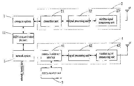
to Referring to Figure 1, an embodiment of an MSN wireless network telephone
system comprises a computer system, a signal transmission controller 2, a
communication unit 3 and a signal transceiver 4. The computer system 1
connects
to a network system 5 via a MSN communication platform 11 to perform signal
transmission. Wireless communication is used between the signal transceiver
controller 2 and the signal transceiver 4.
In this embodiment, the computer system 1 includes a computer device such
as a personal computer or a server that has a display and input unit at the
calling
side or the answering side. The MSN communication platform 11 is a
communication platform installed in tile computer system 1 to connect the
computer
system 1 to the network system 5, so as to perform real-time message
transmission
between a calling party and a receiving party.
The signal transmission controller 2 is connected to the computer system 1
through a connection port 21. Various types or standards can be applied to the
connection port 21. In this embodiment, the connection port 21 includes a USB
2s port. The signal transmission controller 2 has a signal processing unit 22
for
processing and converting message delivered by the MSN COI311TIUiIICati011
platform
-3-
CA 02482386 2004-09-22
11 into a wireless signal, which is then transmitted by a wireless signal
transceiving
unit 23. The wireless signal transceiving unit 23 is also operative to receive
a
wireless signal and feeds it into the signal processing unit 22. The wireless
signal is
then converted into the format readable to the MSN communication platform 11
and
s transmitted to the other side of the network system 5 through the MSN
communication platform 11. The signal transmission controller 2 includes a
wireless network access point, for example.
The communication unit 3 includes a wireless phone allowing mobility of the
calling party or the answering paz-ty within an acceptable range of the
computer
1 o system 1. The communication unit 3 includes a household wireless or wired
telephone, or the ear-phone type communication unit directly connected . to
the
computer system 1.
The signal transceiver 4 electrically connected to the communication unit 3
includes a communication unit interface 41, a signal processing unit 42 and a
1s wireless signal transceiving unit 43. The communication unit interface 4
wireless
signal transceiving unit 43 receives a signal from or transmits a signal to
the
wireless signal transceiving unit 23 of the signal transceiver controller 2.
The signal
processing unit 42 has one end connected to the wireless signal transceiving
unit 43
and the other end connected to the communication unit interface 41. The signal
2o input from the wireless signal transceiving unit 43 or the communication
interface
41 is processed and converted into formats readable to the communication unit
3
and the MSN communication platform 11, respectively. The processed signal is
then transmitted to the communication unit 3 or the MSN communication platform
11. The signal processed by the processing unit 42 is transmitted to the
2s communication unit 3 via the wireless unit interface 4I .
Referring to Figure 2, 'a block diagram for executing wireless telephone
communication via a network system and MSN eonununication platform is
-4-
CA 02482386 2004-09-22
illustrated. In this embodiment, wireless phones are used at both the
receiving end
(answering party) and the transmitting end (calling paz-ty). Through the
network
system 5 and the MSN communication platforms 11 and 11' at both ends, a real
time message .communication can be established. The transmitting end and the
receiving end include the computer systems 1, 1', the signal transceiver
controllers
2, 2', the communication units 3, 3' and the signal transceivers 4, 4',
respectively,
to establish the conversation.
Referring to Figure 3, the method of establish telephone communication
through the network is illustrated. To initiate the communication, each of the
1o calling party and the answering party has to sign ixp the MSN communication
platform 11 and apply a user account in step 600, 600'. When the computer
system
1 of the calling party in step 602 is hooked up to the network system, the MSN
real-
time communication program can be activated and logged on in step 603. The
answering party has to perform the same process to an on-line status. That is,
the
is computer system 1' has to be connected to the network system 5, and the MSN
communication platfoz-m 11' has to be activated and logged on. Thereby,
connection between the MSN communication platforms 11, I 1' of the
transmitting
and receiving ends is established. To initiate a conversation, the calling
panty
activates the communication uzut 3 to send a cozmection signal to the signal
zo transceiver controller 2 of the computer system 1 through the signal
transceiver 4,
such that signal is transmitted between the communication unit 3 and the
computer
system 1 in step 605. The transmitting end can then dials a number, that is,
inputs
the MSN account of the receiving end in step 606 to execute the correction.
When the MSN account of the receiving end is input by the communication
25 unit 3 and processed and transmitted to the computer system 1 via the
signal
transceiver 4, an incoming message is received by the MSN conununication
platfoz-m 11' at the receiving end via the network system in step 607. The
incoming
-5-
CA 02482386 2004-09-22
signal is then identified by the MSN communication platform I 1'. When the MSN
communication platform 11' identifies such incoming signal being a text
message,
such text message is displayed by the screen or monitor of the computer system
1'
at the receiving end. When the incoming message is identified as a signal
s requesting conversation or demanding answering by phone, the incoming
message
is converted to a signal such as a ringing signal and transmitted to the
communication unit 3' by wireless transmission. Various types of ringing
sounds,
vibrations or alerting effects can be generated by the cozrununication unit 3'
to
identify the calling party. The user can then decide whether such call should
be
1o answered or not. The communication between the calling and answering
parties can
thus be established via the MSN communication platforms 11 and 11' in step
614.
When the receiving end does not activate the connection or refuse to answer,
the
computer system I of the calling party will shows the message of failure of
connection.
1 s While the present invention has been particularly shown and described with
reference to preferred embodiments thereof, it will be understood by those of
ordinary skill in the art the various changes in form and details may be made
therein
without departing from the spirit and scope of the present invention as
defined by
the appended claims.
-6-