Note: Descriptions are shown in the official language in which they were submitted.
CA 02482437 2007-12-19
- 1 -
Rolling Device for a Displaceable Cross Frog
The invention relates to a roller device for a movable point
of frog, including a sliding strip and at least one roller and
at least one roller bearing fixed to a stationary part of the
switch.
A device of this type is, for instance, known from WO 94/26976
Al. In that known roller device, an element comprising a
projection extending along, or approximately along, the
central axis of the point of frog departs directly or
indirectly from the point of frog on the side of the foot,
wherein said element interacts with a roller element whose
central axis extends in, or approximately in, a symmetrical
plane extending between the wing rail. In that known device,
the roller guide on which the roller rolls off is, thus,
directly or indirectly connected with the point of frog,
whereby the respective roller is supported by a structure
fixed to the side rails. The roller device known from WO
94/26976 Al serves to support the point of frog at a switching
movement from one abutment position into the other. In order
to cause the point of frog to be lifted from the slide chair
during such switching movement, the roller guide in that case
comprises two outer, concavely extending portions and a
central, preferably plateau-shaped portion on its surface
facing the roller. On the roller guide connected with the
point of frog, a guide track is thus provided, which is
configured in a manner that the point of frog is lifted from
the slide chair as the guide track slides over the roller
element.
Similar roller devices have also become known for tongue
rails, wherein a roller device in which the roller cooperates
with spring elements may, for instance, be taken from WO
94/02682.Al. It has, however, turned out that the known roller
devices are not readily suitable for the subsequent
installation into existing track systems.
CA 02482437 2007-12-19
- 2 -
For the purpose of creating a roller device for a movable
point of frog, which can be readily installed into an existing
system even subsequently without involving any cumbersome
adaptation or adjustment work at the existing rails and, in
particular, the point of frog and wing rails or side rails,
it was proposed in AT 62 18 U to mount the roller in a
roller holder connected with the point of frog and to
connect the roller guide with the wing rails and, in
particular, the rail foot, or with the ground plate. By such a
proposal the subsequent mounting of the roller device was
substantially facilitated due to the fact that, unlike in
known configurations, the roller holder was directly connected
with the point of frog and the roller was thus attached to the
point of frog. Yet, any fine-tuning is still relatively
expensive, calling for a huge number of precisely adapted
structural components. In particular, it is not readily
feasible in that earlier configuration to realize an
appropriate resilient support in a simple manner.
The present inventions aims to further simplify the
installation of a roller device for a movable point of frog
and, at the same time, render feasible the provision of an
appropriate support of the point of frog on several points
along the axial lengths of the point of frog with a minimum of
adjustment work and, in particular, by using identical spring
elements. To solve this object, the configuration according to
the invention consists essentially in that the roller(s)
is/are mounted on an arm of a double-armed lever, that the
pivot bearing of the lever is arranged in a support connected
with a stationary part of the switch, and that the arm facing
away from the roller(s), of the double-armed lever is
pivotable against a spring with adjustable spring power. Due
to the fact that the rollers are mounted on an arm of a
double-armed lever with the pivot bearing of the lever being
arranged in a support connected with a stationary part of the
switch, it is feasible in a particularly simple manner to
CA 02482437 2004-10-13
- 3 -
subsequently simply fix the respective support in order to
simply insert the double-armed lever laterally, thus
substantially facilitating its installation. Due to the fact
that the arm facing away from the roller or rollers, of the
double-armed lever is pivotable against a spring with
adjustable spring power, it is feasible in a simple manner to
define the desired spring power, the adjustability of the
spring power being readily feasible without impediment outside
the region of the movable point of frog. If, as in accordance
with a preferred embodiment of the roller device according to
the invention, the configuration is devised such that the
lever arm ratio of the double-armed levers of a switch is each
selected to be identical and the respectively shorter lever
arm carries the roller(s), it will consequently be feasible
for roller devices neighboring in the longitudinal direction
of the frog to employ identical spring elements, with the
identical setting force being each applicable to adjust said
spring force. It is, therefore, not necessary to define
different spring elements as a function of the installation
situation, and the same setting paths and same setting forces
will each be used in any installation position. In this
manner, particularly simple adjustment and hence particularly
safe subsequent mounting will be ensured in the event of
subsequent mounting.
As already mentioned, the fixation of the support in a
particularly simple manner may be effected to the supporting
structure for the movable point of frog outside the region of
the wing rails. The configuration in this respect in a
particularly advantageous manner is devised such that the
support is fixed to the wing rails or the supporting structure
of the switch, and that the adjustment device for the spring
in top view is arranged outside the wing rails or the
supporting structure, respectively, wherein the pivot bearing
of the lever is provided in a substantially U-shaped support
and, in particular, in or on the side cheeks of said support.
Such a support which is substantially U-shaped in cross
CA 02482437 2007-12-19
- 4 -
section and whose side cheeks carry the pivot bearings of the
lever allows for the insertion of the double-armed lever in
the longitudinal direction of the U-shaped support, and hence
transverse to the longitudinal direction of the rails, and the
pivotal fixation of the same in its respective position in a
particularly simple manner. For fine tuning it will, thus, be
sufficient to position the pivotable lever accordingly and,
after this, adjust the spring to the value that will be
identical for all positions, as a function of the lever ratio.
In this respect, the configuration may advantageously be
devised such that the lever arm ratio is 2:3 to 1:3,
preferably 1:2, so that relatively small-structured springs
will do.
In order to enable the selection of an accordingly favorable
position for the spring with adjustable spring force
irrespective of the respective installation situation of the
support, it is feasible to design the double-armed levers each
having the same lever arm ratio differently for different
installation conditions. In that case, it may be of particular
advantage to devise the configuration in a manner that the
lever arm is designed to be cranked, whereby the individual
roller devices as a function of the structural length of the
movable points of frog may be designed to be substantially
identical in terms of structure except for the lever length.
The adjustment device required for the adjustment of the
spring force may each be positioned where particularly easy
handling is provided.
In one aspect, the invention provides a roller device for a
movable point of frog, the roller device comprising:
a sliding strip and at least one roller running on said
sliding strip;
at least one roller bearing for said at least one roller fixed
to a stationary part of a switch, wherein the at least one
roller is mounted on an arm of at least one double-armed lever;
CA 02482437 2007-12-19
4a
a pivot bearing of the double-armed lever arranged in a
support connected with the stationary part of the switch; and
an arm facing away from the at least one roller of the
double-armed lever, the arm being pivotable against a
spring with adjustable spring power.
In- the following, the invention will be explained in more
detail by way of an exemplary embodiment schematically
illustrated in the drawing. Therein, Fig. 1 is a ground plan
of a switch portion including a movable point of frog; Fig. 2
is a section along line II/II of Fig. 1; and Fig. 3 is a
section along line III/III of Fig. 1.
CA 02482437 2004-10-13
- 5 -
Fig. 1 illustrates a frog with a point of frog 1 as well as
wing rails 2 and 3. Furthermore, a ground plate 4 including a
reinforcement frame 5 and the two locking arrangements 24 and
25 are apparent. The roller devices according to the invention
are denoted by 6 and 7, respectively, wherein, as is apparent
from the views according to Fig. 2 and Fig. 3, the roller
device 7 is fixed to the wing rails 2 and 3 by the aid of a
supporting structure and the roller device 6 is fixed to the
ground plate 4 after the runout of the wing rails.
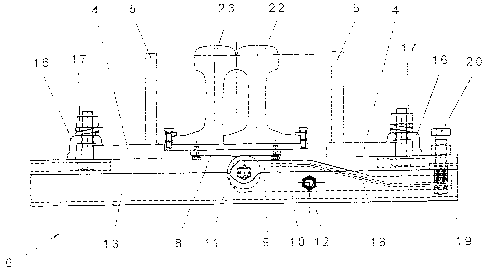
Fig. 2 depicts the roller device 7, wherein the point of frog
1 is in abutment on the wing rail 3 and a slide strip 8 is
connected with the foot of the point of frog 1, said slide
strip 8 cooperating with a roller 11 mounted on an arm 9 of a
double-armed lever 10. The double-armed lever 10, by means of
a pivot bearing 12, is pivotally mounted in a stationary U-
shaped support 13 which is clamped to the wing rails 2 and 3
via brackets 14 and 15 as well as the clamping elements 16 and
screw bolts 17. The arm 18 facing away from the roller 11, of
the double-armed lever 10 is mounted so as to be pivotable
against the spring 19, the spring force of the spring 19 being
adaptable to the respective requirements by the aid of an
adjustment bolt 20.
Departing from the position of the point of frog 1 illustrated
in the drawing, in which the point of frog 1 abuts on the wing
rail 3 and the point of frog 1 abuts on the roller 11 via the
smaller-height portion of the slide strip 8, the point of frog
1 is lifted from the bearing plate at a switching movement in
the sense of arrow 21 by the ramp formed on the slide strip
running onto the roller 11 and thus abutting on the same by
its larger-height portion. The switching movement of the point
of frog 1 is thereby facilitated and the wear minimized. As
the point of frog 1 approaches the wing rail 2, the roller 11
reaches again the smaller-height region of the slide strip via
the ramp illustrated on the left-hand side of the drawing so
CA 02482437 2004-10-13
- 6 -
as to cause the point of frog 1 to abut on the wing rail 2 and
rest again on the ground plate.
Fig. 3 depicts the roller device 6, which, as opposed to the
roller device 7, is not fixed to the wing rails but to the
ground plate 4. In the region of the arrangement of the roller
device 6, the switching movement of the point of frog occurs
over a smaller switching path, and the shape of the guiding
path on the slide strip 8 is, therefore, adapted to the
reduced displacement path. The point of frog 1 in this region
is comprised of the main point 22 and the side point 23. As
for the rest, the reference numerals used in Fig. 2 have been
retained for identical parts.