Note: Descriptions are shown in the official language in which they were submitted.
CA 02482486 2004-09-24
Fuel Cell Power Generation System
Field of the Invention
This invention relates generally to a system for generating electrical power
using hydrogen fuel cells.
Background of the Invention
Reliability of a customer's power supply is a primary concern for a utility.
In order to provide reliable and continuous power, the utility must ensure
that its
equipment is always in working order. Utilities have generating stations, sub-
stations, and telecommunications, system control and computer networks that
must be operating properly at all times. To ensure continuous operation, many
of
these systems are provided with back-up power sources for providing temporary
power whenever their main power sources are disrupted.
For example, a utility has a communications network that includes remote
microwave repeater stations that relay information communicated between sites.
These stations can be located in remote locations such as on a mountaintop,
and
must be provided with back-up power generation means to ensure that the
station remains operational when its primary power source (e.g. commercial
distribution power via ground lines) is interrupted. Typically, such stations
are
fitted with a back-up diesel generator and a number of lead acid batteries.
When
the primary power supply is disrupted, the diesel generators and batteries are
activated to provide nominal A/C and D/C power for periods of time sufficient
for
repair crews to effect necessary repairs.
1
V80275CA1VAN LAW1162871\1
CA 02482486 2004-09-24
Because stations can be located in difficult-to-access wilderness locations,
the stations are provided with large stores of diesel fuel and large numbers
of
lead acid batteries to ensure that enough back up power is available in the
event
repair crews are delayed in reaching the stations. Such remote stations
present
an environmental concern, as the large stores of diesel fuel and battery
electrolyte pose a significant environmental hazard. As these locations are
hard
to reach, timely clean up of fuel or electrolyte spills are particularly
difficult.
It is therefore desirable to minimize or eliminate the environmental risk that
such stations pose by providing a back-up power' source that is relatively
environmentally friendly. Furthermore, such back up power source should be
relatively light and compact: existing back up equipment comprising diesel
generators, diesel fuel storage, and batteries tend to be relatively heavy; as
access to remote stations can often only be made by helicopter, transporting
such equipment and fuel tends to be expensive. Therefore, it is desirable to
reduce the weight of the back up equipment and associated fuel to reduce the
costs associated with constructing and maintaining such stations.
Fuel cell technology has long been touted a commercially viable and
environmentally superior alternative to internal combustion based power
sources.
Generally speaking, fuel cells electrochemically combine hydrogen fuel and
oxidant to produce electricity, water and heat. One type of fuel cell is a
proton
exchange membrane (PEM) fuel cell; such fuel cells employ a membrane
electrode assembly (MEA) which comprises an ion exchange membrane or solid
polymer electrolyte disposed between two electrodes typically comprising a
layer
of porous, electrically conductive sheet material, such as carbon fiber paper
or
carbon cloth. The MEA contains a layer of catalyst, typically in the form of
finely
comminuted platinum, at each membrane/electrode interface to induce the
desired electrochemical reaction. In operation the electrodes are electrically
coupled to provide a circuit for conducting electrons between the electrodes
2
V80275CA\VAN LAW\ 16287111
CA 02482486 2004-09-24
through an external circuit. Typically, a number of MEAs are serially coupled
electrically to form a fuel cell stack having a desired power output.
Due to their zero- or low-emission nature; and ability to operate using
renewable fuels, the use of fuel cells as primary andlor backup power supplies
is
promising. For example, a fuel cell stack have be contemplated for service as
an
uninterruptible power supply for computer, medical, or refrigeration equipment
in
a home, office, or commercial environment. However, actual implementation of
such fuel cell systems in real world applications have been very limited, as
there
are significant technological hurdles to overcome to ensure the fuel cell
systems
can effectively and reliably operate in the field.
Summary
1t is a general objective of the invention to provide a system for generating
electrical power using hydrogen fuel cells. A particular objective is to
provide a
self-contained fuel cell power generation system that is suitable for
providing
backup power in remote field locations to devices having different power
requirements.
2Q According to one aspect of the invention, there is provided a fuel cell
power generation system comprising: a rack for housing at least one fuel cell
stack that generates electrical power having a direct current at a first
voltage; a
hydrogen conduit for coupling the fuel cell stack to a hydrogen supply; and a
power supply electrically coupled to the stack. The power supply comprises
multiple power outlets for outputting power generated by the stack; at least
two
outlets are DC outlets that output direct current at different voltages and at
least
one outlet is an AC outlet that outputs alternating current. The power supply
further comprises at least one DCIDC converter coupled to one of the DC
outlets
and calibrated to convert the first voltage to a second voltage, and a DCIAC
3
V80275CA1VAN LAW116287111
CA 02482486 2004-09-24
inverter coupled to the AC outlet and calibrated to convert the direct current
of
the generated power to alternating current.
Brief Description of the Drawings
Figure 1 is a simplified power wiring and hydrogen piping schematic of a
fuel cell power generation system according to one embodiment of the
invention,
wherein thicker black lines indicate hydrogen flow and thinner black lines
indicate
power filow.
Figures 2(a) and (b) are front and side views of the fuel cell power
generation system without a hydrogen supply assembly.
Figures 3(a) to (d) are front, side, plan and rear views of a power supply
module of the fuel cell power generation system.
Figure 4 is a simplified communications wiring schematic for the fuel cell
power generation system.
Detailed Description Of Embodiments of the Invention
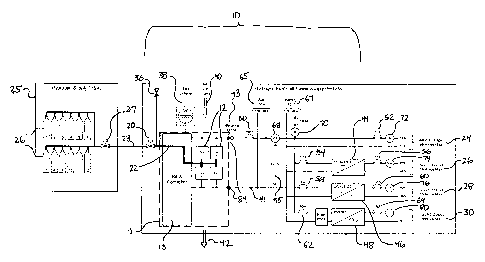
Referring to Figure 1, a fuel cell power generation system 10 is provided
that can simultaneously supply a flow of alternating current and direct
current
electrical power, and simultaneously supply direct cun-ent electricity at
multiple
voltages. The system 10 produces electricity from a fuel cell module 11
comprising a plurality of fuel cell stacks 12 and a rack controller 13. The
system
10 is particularly suited to serve as a source of back-up power for remotely
located repeater stations used by the utility industry. However, it is
expected that
the system 10 will be suitable for many other applications, wherein electrical
devices require power from a self-contained, relatively compact power source.
4
V80275CA\VAN LAW1162871\1
CA 02482486 2004-09-24
The fuel cell module 11 can be obtained from a fuel cell manufacturer,
such as the NEXA~ RM series fuel cell module platform manufactured by Ballard
Power Systems Inc. of Burnaby, British Columbia. The fuel cell module 11
comprises four fuel cell stacks 12, from Ballard's NEXA~ RM model of fuel cell
stacks; however, a different number of fuel cell stacks 12 may be substituted
depending on the power demanded from the system 10. These fuel cell stacks
12 are each configured to provide a power output in 1 kW, 24 VDC nominal
(regulated) at 40 amps steady state from a supply of gaseous hydrogen. The
four fuel cell stacks 12 are arranged into two series-connected pairs. Each
pair
produces 48 VDC and are coupled together in a parallel electrical connection,
thereby resulting in a total stack output of 48 VDC. The fuel cell module 11
also
comprises batteries (not shown) that provide interim power during fuel cell
stack
start up. The rack controller 13 is programmed to monitor and control the
operation of the fuel cell stacks 12, and is provided with a plurality of
contacts
including "output system OK" and "output requested" outputs. The controller 13
can be readily programmed by the manufacturer to communicate additional data
as needed by the system 10, e.g. additional contacts can be programmed to
output additional data such as stack temperature, voltage, and current .
While the system 10 is particularly suitable for use with the Ballard fuel
cell
module platform, other fuel cell modules that produce direct current
electricity
can be readily substituted. Such alternative fuel cell stacks can be PEM
stacks,
or other fuel cell types as is known in the art, such as solid oxide fuel cell
(SOFC)
stacks. Such stacks can operate with pure gaseous hydrogen, or from a
reformate produced from a reformer as is known in the art.
Referring to Figures 1 and 2(a) and (b), a rack 14 is provided for housing
the four fuel cell stacks 12 in a vertical stack. The rack 14 can be modified
with
additional mountings to accept a different number of stacks 12 depending on
need. The rack 14 has a steel frame with a base 18 and an industry standard 19
inch rack mounting width. The bottom four rack mounts are configured to
receive the four fuel cell stacks 12. The rack mounting immediate above the
fuel
5
V80275CA1VAN LAW\ 162871\1
CA 02482486 2004-09-24
cell rack mountings contains a DC-to-AC power inverter 48. The rack mounting
above the power inverter 48 contains a power supply module 16. The rack
mounting above the power supply module 16 contains a monitoring,
annunciation, and control module ("MAC module") 17 which is communicative
with the fuel cell module 11 and power supply module 16, and to an external
communications network via intranet or Internet.
Referring to Figure 3(c), the power supply module 16 has a pair of power
terminals 84 that electrically couple the power supply module 16 to the power
output from the fuel cell module 11. Referring back to Figure 1, the power
supply
16 electrically couples the power inverter 48 to the terminals 84 via a
parallel
connection bus bar 45.
The power inverter 48 contains the necessary components for converting
the 48 VDC electricity produced by the fuel cell stack 12 into 120 VAC power;
an
AC outlet 30 is coupled to the inverter 48. The power supply module 16 also
serves to convert 48 VDC electricity produced by the fuel cell stack 12 into a
plurality of DC voltages, namely, 48 VDC at outlet 24, 24 VDC at outlet 26,
and
12 VDC at outlet 28. These outlets 24, 26, 28, 30 are particularly suitable
for
providing back-up power to various devices in a repeater station: the 48 VDC
outlet 24 can provide 48 VDC power to a microwave repeater unit (not shown)
for
relaying data signals, the 24 VDC outlet 26 and 12 VDC outlet 28 can each
provide power to a VHF radio (not shown) for relaying voice signals, and AG
power can provide AC power to an air compressor (not shown) that serves to
prevent condensation in a microwave wave guide of the microwave repeater unit.
Optionally, different AC and DC output voltages can be provided
depending on need, e.g. when the system 10 is used in applications other than
repeater stations.
Continuing to refer to Figure 1, the fuel cell module 11 is supplied
hydrogen fuel from a hydrogen supply assembly 25 comprising a plurality of
pressurized gaseous fuel cell tanks 26. The fuel tanks 26 are industry
standard
6
V80275CA1VAN LAW1162871\1
CA 02482486 2004-09-24
pressure tanks for storing hydrogen gas under pressure. Suitable such tanks
are
hydrogen storage tanks manufactured by Dynetek Industries Ltd. of Calgary,
Alberta. For supplying back up power to remote repeater stations, it is
desirable
to install twelve 5000 psig gaseous hydrogen storage tanks to provide
continuous
back up power for up to three days depending on load demands. However, a
different number of storage tanks with different pressure ratings can be
provided
depending on need.
Optionally, the system 10 and hydrogen supply assembly 25 can be
housed in a system enclosure (not shown). The system enclosure 32 has a
partition wall that separates the enclosure into two rooms; the system 10 is
housed in one room and the hydrogen supply assembly 25 is housed in another
room; the partition wall can be seated to prevent gas flow between the two
rooms. Such sealing is desirable to reduce the chances of explosion caused by
hydrogen leaked from the tanks 26 which comes into contact with electrical
components in the system 10. The enclosure enables the system 10 and
hydrogen supply assembly 25 to be stored outside of the repeater station, and
can be insulated and otherwise configured to protect the components of the
system 10 and hydrogen supply assembly 25 from the environment.
Alternatively, the system 10 can installed inside the station and the hydrogen
supply assembly 25 can be housed in an enclosure (not shown) and stored
outside the station; hydrogen supply piping can be extended to couple the
tanks
26 to the fuel cell module 11.
The tanks 26 are all fluidly coupled to a common header 23, which is
coupled to a outlet valve 27. Pressure regulators (not shown) are coupled to
the
header to reduce the operating pressure of the fuel cell module 11. A pressure
meter (not shown) is coupled to the pressure regulator and a flow rate meter
(not
shown) is coupled to the header upstream of the regulator; these two meters
are
communicative with a hydrogen supply monitoring and control module (HSMC
unit) 29 located inside the hydrogen supply assembly 25.
V80275CA\VAN LAW1162871\1
7
... . _ ~.._. _ _ t
CA 02482486 2004-09-24
A hydrogen fuel inlet valve 20 is provided at the rear of the rack base 18
(see Figure 3) and is fluidly coupled to the hydrogen supply assembly outlet
valve 27 by suitable piping. Hydrogen supply piping 22 extends from the inlet
valve 20 to each of the fuel cell stacks 12 and supplies hydrogen fuel to each
of
the fuel cells in the fuel cell module 11. The design and layout of such
piping is
conventional and thus not described here in detail. Oxidant for the fuel cells
is
obtained from ambient air. An air intake 40 is provided in the structure that
houses the system 10 (e.g. the station or a dedicated enclosure) to ensure
sufficient oxidant is supplied to the fuel cell module 11. A water drain 42 is
coupled to each fuel cell and collects and removes product water produced by
the fuel cells from the system 10.
A pressure relief valve 36 is coupled to the hydrogen piping 22 upstream
of the fuel cell module 11, and is located near vents (not shown) in the
ceiling of
the enclosure I station and is configured to open when the hydrogen supply
pressure exceeds a predefined threshold. As hydrogen is lighter than air,
hydrogen gas vented through the relief valve 36 will dissipate into the
atmosphere. As a safety precaution, an exhaust fan 38 is provided near the top
of the rack 14 and facilitates air flow exchange between the inside and
outside of
the rack 14, to prevent hydrogen from accumulating within the enclosure I
station. The fan 38 is located in the vicinity of the fuel cell stacks 12 and
the
power supply module 16 and also serves to cool the stack and other heat
producing components. A suitable cooling fan is a 102 CFM 48 VDC muffin fan,
model no. 030573. The fan 38 is powered by the system 10 and is electrically
coupled to the inverter 48.
The electrical terminals 84 are coupled to the power outlets 24, 26, 28, 30
by wiring circuit 41. A blocking diode 43 is provided on the wiring circuit 41
immediate downstream of the terminals 84 to prevent electrical backflow into
the
fuel cell module 11. The wiring extending from the terminals 84 connects to a
parallel connection bus bar 45 which is in turn coupled to each of the four
electrical outputs, namely, the 48 VDC output 24, the 24 VDC output 26, the 12
8
V80275CA\VAN LAW\ 162871\1
CA 02482486 2004-09-24
VDC output 28 and the A/C output 30. Connected to the wiring between the 24
VDC output 26 and the bus bar 45 is a 300 watt 48 VDC to 24 VDC converter 44
("DC to DC1 converter"). Connected to the wiring between the 12 VDC output 28
and the bus bar 45 is a 150 watt 48 VDC to 12 VDC converter 46 ("DC to DC2
converter"). Suitable converters can be those manufactured by Absopulse, such
as models BAP65-P3326 and DCW150-12-FT respectively. Connected to the
wiring between the A/C output 30 and the bus bar 45 is the inverter 48,
namely, a
1500 VA 48 VDC to 120 VAC type inverter; a suitable inverter can be one of
those manufactured by Absapulse, such as model CSi-1.5K-4-19"-A. A current
transformer (not shown) is provided down-current from the inverter 48 and
serves
to reduce the AC output current from 50 A to 5A; a suitable such transformer
can
be one made by Electro-meters, model no. 2SFT-500. A voltage transformer
(not shown) is provided beside the current transformer to transform the AC
voltage from 115V:25 VCT; a suitable such transformer can be on made by
Frost, model no. TRC-25F. Optionally, a 115 V A/C receptacle (not shown) can
be coupled to the wiring circuit 41 between the inverter 48 and the AC voltage
and current transformers to provide 115 VAC output.
Various circuit breakers are installed at various locations along the
electrical conduits, to interrupt electricity flow between components in the
system
10; these circuit breakers are communicative with switches at the front of the
power supply module 16 to enable an operator to control the system 10 on site,
as well as to the MAC module 17 to enable the system 10 be controlled
remotely.
In particular, a 100 ADC, 65 VDC 25 KA1C, AUX SW circuit breaker ("fuel cell
output circuit breaker") 50 is installed on the wiring circuit 41 between the
terminals 48 and the bus bar 45 and serves to cut the fuel cell module 11 from
all
of the outlets 24, 26, 28, 30; a suitable such circuit breaker is manufactured
by
Heinemann, model no. CD1-B2-U-0100-02C. Additional circuit breakers are
installed on the wiring circuit 41 between the bus bar 45 and each of the DC
and
AC outputs, namely: a 60 A 48 VDC output circuit breaker 52 for cutting the 48
VDC output from the circuit 41, a 10 A DC-DC1 input circuit breaker 54 and 12
A
DC-DC1 output circuit breaker 56 on the circuit 41 before and after the DC-DC1
9
V80275CA1VAN LAW\ 162871\1
CA 02482486 2004-09-24
converter 44; a 5 A DC-DC2 input circuit breaker 58 and a 12 A DC-DC2 output
circuit breaker 60 on the circuit 41 before and after the DC-DC2 converter 46;
and, a 50 A inverter input circuit breaker 62 and a 15 A inverter output
circuit
breaker 64 on the circuit 41 before and after the inverter 48. Suitable
circuit
breakers are known in the art, and can for example, be obtained from
Heinemann.
Electrically coupled to the electrical conduit down-current of the stacks 12
is an auxiliary input terminal 65 used to connect the system 10 to an external
DC
power source that can be used to supply power to each of the outlets 24, 26,
28,
30. In such event, the fuel cell stacks 12 are isolated by opening the fuel
cell
output circuit breaker 50.
Electrically coupled to the wiring circuit 41 between the auxiliary terminal
65 and the bus bar 45 is a battery terminal 67. The battery terminal 67 can be
coupled to a pack of rechargeable batteries ( not shown) that are found in a
conventional back-up power source for repeater stations. Such conventions!
back-up power source typically comprises a diesel generator (not shown)
electrically coupled to a battery charger (not shown) which in turn is
electrically
coupled to the batteries. The batteries are coupled to a bus bar (not shown)
which have outlets which are coupled to each of the devices in the repeater
station. When primary power (from an AC power grid) is interrupted, the
batteries
supply back up power and are recharged by the diesel generator. It is expected
that the system 10 can be retrofit to existing repeater stations by replacing
the
diesel generator with the system 10 and coupling the system to the batteries
via
the battery terminal 67. These batteries can be used to provide immediate back-
up power when the primary power supply is interrupted; the batteries provide
power long enough for the fuel cell module 11 to reach normal operating
status.
As the batteries tend to drain over time, even when not used, the system 10 is
programmed to continuously charge the batteries.
Alternatively, the batteries can be eliminated altogether, and the devices in
V80275CA1VAN ~AW1162871\1
CA 02482486 2004-09-24
the repeater station can be connected directly to the system 10 via the
outlets 24,
26, 28, 30; it is expected the batteries on board the fuel cell module 11 can
supply sufficient power until the fuel cell stacks 26 are started and reach
normal
operating status.
A number of sensors are installed in the system 10 to monitor the
operation of the system 10. A fuel cell output voltage meter (0-75 VDC) 68 is
installed on the circuit 41 between the terminals 84 and the bus bar 45 to
measure fuel cell module 11 output voltage; a fuel cell output current meter
(0-
100 ADC, 50 mV Shunt) 72 is installed on the circuit; 41 at the 48 VDC outlet
24
to measure fuel cell module 11 current output; a battery current meter (900-1-
100
ADC, 50 mV Shunt) 70 is installed on the circuit 41 at the main battery
terminal
67 to monitor current drain from terminal 67; DC current and voltage meters
are
installed at each of the DC outputs, namely: a 24 VDC current and voltage
meters (0-30 VDC, 0-15 ADC, 50 mV shunt) 74 at the 24 VDC output; and a 12
VDC current and voltage meters (0-15 VDC, 0-15 ADC, 50 mV shunt) 76 at the
12 VDC output. Also, output voltage and current inverter meters (0-150 VAC, 0-
15 AAC) 80 are installed at the AC output 30
Referring to Figures 3(a) to (d), the converters 24, 26, 28, inverter 30,
circuit breakers 50, 52, 54, 56, 58, 60, 62, 64, meters 66, 68, 70, 72, 74,
76, 80,
and rack controller 82 and electrical conduits connecting these components,
are
all located inside the power supply module 16. At the front of the power
supply
module 16 are multiple displays 86 each communicative with one of the meters
66, 68, 70, 72, 74, 76, 80, that display the readings taken by each of the
meters
66, 68, 70, 72, 74, 76, 80. Switches 88 are each communicative with one of the
circuit breakers 52, 54, 56, 58, 60, 62, 64, and can be toggled to isolate or
connect each of the outlets 24, 26, 28, 30 from the fuel cell module 11. A
master
switch 90 is coupled to circuit breaker 50 to isolate or connect the fuel cell
module 11 from the system 10. These displays 86 and switches 88, 90 enable
an operator on site to monitor and manually control the operation of the
system
10.
11
V80275CAlVAN hAW1162871\1
CA 02482486 2004-09-24
Referring to Figure 4, each of the meters 58, 70, 72, 74, 76, 80, are
electrically communicative with and send data to the MAC module 17 via input
contacts 11, 12, 13, 14, 15, Is. The MAC module 17 is communicative with and
controls the operation of each of the circuit breakers 50, 52, 54, 56, 58, 60,
62,
64 via output contacts 01, 02, 03, 04, O~, 06, 07, O8, The MAC module 17 is
communicative with and receives data from the rack controller 13 of the fuel
cell
module 11 via input contacts 17 and I8, namely, "system output OK" and "output
requested" inputs. The former input indicates that the fuel cell module 11 is
in
ready operating condition and the latter input indicates that the fuel cell
module
11 requires hydrogen fuel from the tanks 26. Additional inputs can be
established
between the MAC module 17 and the rack controller 13 if additional information
is desired from the fuel cell module 11. The MAC module 17 is communicative
with and controls operation of the fuel cell module 17 via output terminal O9.
The
status of the primary power supply (AC power grid) is monitored by the
dedicated
sensor 80 or by a (ike sensor in the battery charger if the system 10 is
coupled to
back-up batteries; this sensor is communicative with the MAC module via input
terminal l9.
The HSMC module 29 is communicative with and receives data from
pressure and flow rate meters from the hydrogen supply assembly 25 via input
contacts 110, 111. The HSMG module 29 also is communicative with and receives
data concerning the status of the exhaust fan 38 and a hydrogen concentration
sensor 82 located inside the enclosure housing the hydrogen supply assembly
25. The HSMC module 29 controls output valve 27 via output contact 01o and
communicates with the MAC controller 17 via input 1 output terminal 1/03.
An external communications port 1/01 connects the MAC module 17 to the
utility's communications network, and allows operators at locations remote
from
the station to monitor the condition of the system 10 via the meters 68, 70,
72,
74, 76, 80, and to control the operation of the system 10 and hydrogen supply
assembly 25.
12
v80275CA1vAN LAW\ 162871\1
CA 02482486 2004-09-24
The system 10 can be operated in two distiulct modes. The operating
mode depends on whether the system 10 acts as a charger for maintaining the
charge in a bank of back-up batteries coupled to terminal 67, or whether the
system provides back up power directly to devices coupled to outlets 24, 26,
28
and 30. When acting as the direct back-up power supply, the fuel cell module
17
is shut off and the outlet valve 27 is closed when the primary power source is
supplying power to the station. When the primary power source sensor 80
detects that the primary power source is interrupted, the MAC module 17, HSMC
module 29 and exhaust fan 38 switch over to battery power from batteries
inside
the fuel cell module 11.
Then, when the following conditions are met, the HSMC module 29 and
MAC module 17 instruct the fuel cell module 11 to activate:
battery charger sensor 80 indicates primary power source interrupted (I9);
exhaust fan 38 is operating (I12)~
hydrogen sensor 80 indicates that hydrogen concentration is within
acceptable parameters (113), and
fuel cell module 11 is in operating condition (17) and is ready to accept fuel
(Is).
The HSMC module 29 then opens the conltrol valve 27 and hydrogen
starts to flow from the tanks to the fuel cell module 11. The MAC controller
17
monitors the output of the fuel cell module via inputs 11, 12, 13, 14, 15,
16., and
communicates this data to an operator via the communications network
connection. The operator can shut off the system 10, or isolate individual
terminals 65, 67 and outlets 24, 26, 28, 30 of the system 10 via outputs 01,
02, _
03, 04, 05, 06, 07, O8. Alternatively, the controller 82 can be a programmable
logic device programmed to monitor and control the operation of the system 10
automatically.
13
V80275CA\VAN LAW\ 16287111
CA 02482486 2004-09-24
When the system 10 acts as a charger for a bank of back-up batteries, a
sensor in the batteries is connected to the MAC module 17 and monitors the
charge level in the batteries. When the charge drops below a predefined
threshold, the fuel cell module 11 is started in the same way as described
above.
While the present invention has been described herein by the preferred
embodiments, it will be understood to those skilled in the art that various
changes
may be made and added to the invention. The changes and alternatives are
considered within the spirit and scope of the present invention.
14
V80275CA\VAN LAW116287111