Note: Descriptions are shown in the official language in which they were submitted.
CA 02482557 2009-01-16
IMPROVED APPARATUS FOR WASTE GASIFICATION
BACKGROUND OF THE INVENTION
Many attempts have been made at creating waste disposal systems that
eliminate or reduce the need to landfill municipal solid waste ("MSW").
Traditional approaches have included incineration and pyrolysis. Conventional
incineration however is objectionable because the high bum temperatures in the
presence of oxygen results in the formation of coinplex pollutants that are
difficult
and expensive to control. Furthermore, the vast majority of incinerated
organic
material is converted into undesirable carbon dioxide, which is implicated in
global warming, ozone layer depletion, and the formation of volatile organic
compounds. The incineration process also releases nitrogen oxides that
contribute
to smog problems in urban areas. The pyrolysis procedure involves the
conversion
of various materials into a glass like residue in an oxygen depleted, high
temperature environment. However, the high temperature, depleted oxygen
environment of pyrolysis creates some extremely toxic compounds. Furthermore,
pyrolysis is an inefficient method for disposing large volumes of waste
materials,
and the residual ash material contains large amounts of carbon.
Many of the disadvantages of incineration and pyrolysis are overcome by
waste gasification. Waste gasification involves supplying the minimum amount
of
oxygen necessary to cause a thermo-chemical reaction that releases simple
combustible gases at a controlled temperature, without supplying enough oxygen
to cause combustion. When feed stock materials, such as MSW, that are rich in
energy as measured by British thermal units, are loaded into gasification
reactor
chambers, and are exposed to a controlled temperature, oxygen depleted
environment, such solid, sludge, or liquid feed stock materials are converted
into a
1
CA 02482557 2009-01-16
heavy vapor gas fuel. Materials that are rich in energy include, but are not
limited
to, coal, wood, cardboard, paper, industrial scrap, plastics, tires, organic
wastes,
sewage cake, animal waste, and crop residue, or a combination thereof. The
released heavy vapor fuel gas is then mixed with oxygen and burned. Examples
of
prior gasification systems are shown in U.S. Pat. No. 4,941,415 and U.S. Pat.
No.
5,941,184.
The material remaining after the completion of the gasification process
cycle is composed of incombustible materials, including metals, glass, and
ceramics, along with a fine inert salt and mineral power residue, and has a
greatly
reduced volume that is suitable for remanufacturing into concrete material or
land
filling. Furthermore, recyclable materials that do not undergo phase
transition,
such as all recycle glass, aluminum, metals, residual materials and salts, are
recoverable after the gasification process, thereby eliminating the need for
pre-
sorting or processing the in-bound feed stock material.
Conventional prior art gasification systems are multi-step processes that
generally utilize four open-looped process steps. These four steps typically
involve: one or more primary gasifiers; a central air mixing chamber; a
secondary
processor for combusting the produced heavy vapor gas fuel; and final air
cleaning
systems. However, conventional gasification systems have proved difficult to
cost-
effectively construct. Therefore, a need exists for a simplified gasification
apparatus that is inexpensive to build, simple to operate, and yet achieves
the
benefits of producing a gas fuel from solid waste feed stock materials.
Furthermore, prior art open-looped systems, such as U.S. Pat. No.
6,439,135, utilize exhaust stacks that release hot gases from the final
combustion
step into the atmosphere, or use storage tanks to collect the hot gases for
future
ancillary purposes, rather than reclaiming at least a portion of the cleaned
air for
2
CA 02482557 2009-01-16
re-introduction into the gasification process. Furthermore, such prior art
systems
do not teach a gasification system that produces a relatively pure carbon
dioxide
for other industrial purposes or to support the augmentation of vegetation,
such as
a greenhouse, a carbon dioxide dispersal system, or an aquaculture bed.
Current research indicates that increasing the surface area of feed stock
material that is exposed to gasification process gas significantly improves
the
production rate of fuel gas from the feed stock materials. Yet, prior art
gasification
systems, such as those illustrated in U.S. Pat. No. 6,439,135 and 5,619,938,
utilize
reactor chamber configurations that expose only limited feed stock surface
area to
gasification process gas. Such prior art systems incorporate reactor chamber
configurations where only the bottom of the feed stock at grate level, known
as the
primary reaction zone, and the uppermost surface of the feed stock, known as
the
secondary reaction zone, are exposed to optimum gasification conditions.
As a result, gasification of the tons of feed stock material that is not
located
at either the primary or secondary zones, such as that on the sides and center
of the
reactor chamber, requires that the temperature and duration of the
gasification
cycle be increased. Yet higher gasification temperatures tend to reduce the
Btu
content of the resulting heavy vapor fuel gas. The high operating temperatures
also
increase the time required for cooling the gasification chamber to a
temperature
suitable for the loading and disposal of subsequent loads of feed stock
materials.
Furthermore, the costs associated with obtaining and maintaining the higher
gasification temperatures, along with the cost of fabricating a complex
gasification
reactor chamber that can withstand prolonged exposure to high temperatures,
also
increase. Current gasification chambers are lined with various clay-based
insulative/refractory materials. These refractory materials maintain
gasification
reactor temperatures while also preventing structural damage to the reactor
3
CA 02482557 2009-01-16
chamber's steel superstructure and surface paint from prolonged exposure to
excessive heat. Refractory material is usually applied to the gasification
reactor
chamber as pre-cast panels, bricks, or sprayed on as a gahnite-like
application.
Such refractory material is affixed to the exterior steel jacket of the
gasification
reactor chamber by refractory hangers, which are heavy metal dowels in the
form
of hooks. With typical prior art systems, a 2 to 4 inch layer of ceramic fiber
blanket is usually inserted between the refractory material and the steel
jacket
before the refractory layer is installed to offer additional thermal
protection for the
exterior steel surfaces of the gasification reactor chamber.
Application of refractory material is thus labor intensive, time consuming,
and a significantly expensive step. Additionally, the weight of the refractory
liner
necessitates that the steel vessel be constructed from at least 1/4 inch thick
hot
rolled A36 steel plate and heavy structurals. This additional superstructure
weight
further increases the overall cost of manufacturing, shipping, and
installation.
An additional problem with the use of refractory material is the length of
time required for cooling the gasification reactor chamber before it can be re-
used
to gasify a subsequent load of MSW. More specifically, a subsequent
gasification
process typically cannot begin until the gasification reactor chamber has
cooled to
approximately 150 degrees Fahrenheit. Yet, at the end of a process cycle, the
clay
refractory material tends to retain heat for a long period of time. Depending
on the
particular chemistry of the refractory material, this retention of heat may
require
that the gasification chamber be inoperative for several hours as the
temperature of
the chamber, and associated refractory material, cools down.
The limited feed stock capacity of prior art gasification systems often
required the construction of multiple gasification reactor chambers to meet
demand requirement. In previous designs, gasification reactor chambers
typically
4
CA 02482557 2009-01-16
have a rectangular configuration. As the length of the rectangular sidewalls
is
increased to satisfy larger feed stock capacity requirements, the size of the
reactor
chamber creates problems associated with providing sufficient clearance space
away from the prolonged high temperatures of the reactor chamber. This problem
typically limits reactor chambers to configurations that are approximately 20
feet
high, 20 feet wide, 20 feet long. Such a configuration however has a limited
load
capacity of approximately 50 tons of feed stock material. Furthermore, as the
size
of the rectangular configuration is increased, problems develop with the side
load
waste dump arrangement. More specifically, as the rectangular sidewalls extend
beyond 20 feet, the angle of repose of the trash spilling out of the garbage
truck
typically only fills a small portion of the reactor chamber's near sidewall.
Because the heavy vapor fuel gas has been produced in an environment that
typically contains no more than 8% oxygen, waste gasification systems must
also
increase the level of ambient oxygen in the gas produced in the gasification
reactor
chamber to make it fully flammable. This often requires increasing the oxygen
content of the heavy vapor fuel gas to approximately 15% to 20%.
Prior art gasification systems increased the oxygen content of the heavy
vapor fuel gas by directing the heavy vapor fuel gas through air mixing
chambers.
These mixing chambers are typically large, cylindrical vessels, with a variety
of
air induction tubes attached to multiple blower fans that flood the air mixing
chambers with outside air using air compressors or high velocity fans. Yet
because
of the large size of these chambers, they require substantial fabrication and
installation time, and as a result are expensive. The use of fans and/or air
compressors also increases the initial cost of the system and operating and
maintenance expenses.
CA 02482557 2009-01-16
Conventional gasification systems also use cumbersome techniques for
moving fuel gas to the point of combustion. Such systems often vent, or
breech,
the fuel gas from the top or at least one side of the reactor chamber, and
direct the
vented fuel gas from the reactor chamber into a secondary gas processor, which
is
usually driven by a natural draft current that is created by hot air in the
system
rising through an exhaust stack. The fuel gas' exit from the reactor chamber
is
controlled by a motor driven damper assembly that regulates the varying flow
of
produced fuel gas from this first process step into ducting that connects the
gasification reactor chamber to the secondary air mixing chamber. Such systems
typically require large diameter piping to draw the gas off from the
gasification
chamber. This large piping, and associated ductwork, increases not only
equipment cost, but also installation expenses.
A further disadvantage of traditional air draft systems is that heavy vapor
fuel gases have a tendency to linger in the gasification reactor chamber, and
become subject to accidental combustion, which ultimately lowers the Btu
content
of the extracted heavy vapor fuel gas. This problem is exacerbated by the
inconsistency of up-draft air movement in a natural draft system. Humidity,
wind,
barometric pressure and outside temperature all affect the rate of flow
through a
natural draft system. This inconsistent flow causes the evacuation of gases
from
the reactor chambers to frequently stall, produces negative results in the
process,
and adversely effects the total cycle time for the gasification of the feed
stock
material.
Furthermore, the combustion of the heavy vapor fuel gas in a hot water
heater, steam boiler, refrigeration unit, or other industrial process,
produces a
relatively high temperature exhaust. Yet, prior art systems often vent this
hot
combusted exhaust into the atmosphere at a temperature between 1200 and 1600
degrees Fahrenheit, thereby wasting a significant thermal resource that could
be
6
CA 02482557 2009-01-16
further captured and directly utilized in other heat dependent applications,
thereby
preserving natural resources and providing a cost efficient source for heated
gas.
Hot combusted exhaust that is vented into the atmosphere in prior art
systems via an exhaust stack also often contain large quantities of carbon
dioxide.
While carbon dioxide is not currently regulated as a pollutant from solid
waste
incinerators, it is subject to various industrial air quality abatement
initiatives.
Furthermore, by recapturing the thermal energy that is entrained in the
exhaust for additional attached applications, and thereby continuing to reduce
the
ultimate exhaust temperature of the exhaust gas, the volume of the exhaust
decreases. As the volume of the exhaust gas is reduced, the conveying piping
and
other gas handling equipment, along with associated equipment costs, also
decrease.
It is therefore an object of the present invention to provide a gasification
system capable of gasifying feed stock at a reduced temperature and time.
It is another object of the present invention to decrease the time between
subsequent uses of the gasification reactor chamber.
It is another object of the present invention to reclaim at least a portion of
the exhaust air for re-consumption in the gasification process.
It is a further object of the present invention to provide a gasification
system that produces a high Btu content vapor gas.
7
CA 02482557 2009-01-16
It is another object of the present invention is to provide an inexpensive to
build, simple to operate, gasification system that provides the benefits of
producing a fuel gas from feed stock material.
It is another object of the present invention to provide for improved gas
collection that allows for both simpler gasification reactor chamber
configurations
and an improved gas flow design that allows for better final combustion.
It is another object of the present invention to provide a gasification system
that eliminates the need to rely on multiple gasification reactor chambers to
provide an increased system volume capacity.
It is a further objective of the present invention to capture and sequester
carbon dioxide produced by the gasification system, and to use the sequestered
carbon dioxide in a beneficial manner.
It is another objective of the present invention to improve the quality of the
final exhaust air from the present invention sufficiently to re-introduce the
recycled process gas into the gasification system, thereby creating a closed-
loop
system.
These and other desirable characteristics of the present invention will
become apparent in view of the present specification, including the claims and
drawings.
BRIEF SUMMARY OF THE INVENTION
The present invention is directed to a system for the gasification of a
variety of waste streams, including, but not limited to, agricultural,
industrial, and
8
CA 02482557 2009-01-16
municipal waste streams. More particularly, the invention relates to a
gasification
system that incorporates a self sustaining gasification chamber that has its
own
dedicated flare assembly, and which is capable of gasifying large volumes of
feed
source material without the need for multiple gasification chambers. This self-
sustaining gasification chamber and flare assembly are also capable of being
used
with other self-sustaining chambers to feed at least one common heat recovery
device. Furthermore, the present invention is a closed-loop system, which
eliminates the need for an exhaust stack, and which recovers heat entrained in
hot
exhaust, thereby producing a cooled exhaust that is subsequently filtered and
separated from carbon dioxide, and which is suitable for re-introduction in
the
gasification procedure. Removed carbon dioxide may then be used for other
industrial operations, or may be used to support the augmentation of
vegetation,
such as a greenhouse or a carbon dioxide dispersal system, whereby vegetation
converts the carbon dioxide into oxygen that may also be recaptured for re-
introduction in the system of the present invention.
In one embodiment of the present invention, the gasification system is
comprised of a gasification reactor chamber, an aspirator, a flare assembly,
at least
one heat recovery device, an absorber, and an extractor.
MSW is loaded into the gasification reactor chamber for gasification,
whereby the MSW serves as feed stock material. The reactor chamber is
comprised of an interior chamber and an outer shell. Although the gasification
reactor chamber of the present invention may have a number of shapes,
including
being rectangular, square, or cylindrical, the reactor chamber of the
preferred
embodiment of the present invention has at least five sidewalls and includes
perforated conduits or an inner liner. The perforate conduits or inner liner
increase
the surface area of the feed stock material that is exposed to optimum
gasification
conditions, thereby decreasing both the gasification cycle time and
temperature,
9
CA 02482557 2009-01-16
while also decreasing the time between additional gasification procedures on
subsequently loaded feed stock material. The reduction in the gasification
temperature also allows for the fabrication of the gasification chamber from
lighter
gage material, and eliminates the need for refractory material, thereby
reducing the
weight of the gasification system and the time and expense associated with its
fabrication. Furthermore, gasification conditions may be controlled by a
process
logic controller, which is used to control the gas content and temperature in
the
interior chamber.
An aspirator assembly, through the use of a motor, is used to create a
negative pressure in the interior chamber, thereby allowing for the smooth and
even evacuation of heavy fuel vapor gas. As the motor blows ambient air into a
conduit coupling, a suction force is created in the conduit coupling and
attached
single gas manifold and gas siphon assembly. This suction force pulls the
heavy
vapor fuel gas from the interior chamber and into the conduit coupling. The
efficient extraction of heavy vapor fuel gas afforded by the aspirator
assembly also
prevents the occurrence of accidental combustion that may lower the Btu
content
of the desired fuel gas.
The ambient air used by the aspirator to create the suction force is mixed
with the heavy vapor fuel gas in the conduit coupling, thereby eliminating the
need
for a separate mixing chamber. Furthermore, control of the motor and the
selected
size of the tubing and conduit allow for finite control of the volume of gas
that
moves through, and is mixed by, the aspirator assembly. The aspirator assembly
of
the present invention also eliminates the need for a damper.
Mixed gas exiting the aspirator then enters a flare assembly. In the
preferred embodiment of the invention, the flare assembly includes a targeting
nozzle that has a conical funnel configuration. The configuration of the
targeting
CA 02482557 2009-01-16
nozzle allows for additional mixing of the gases, increases the velocity of
the
mixed gas so as to provide back pressure in the system, and creates a focus
point
for combustion. Back pressure created by the conical funnel configuration not
only
aids in the smooth operation of the at least one common heat recovery device,
but
allows the system to incorporate heat recovery devices that have minimum
positive input pressure requirements.
In the preferred embodiment of the present invention, the flare assembly is
built in, or is a sub-component of, at least one primary heat recovery device.
The
combustion of the mixed gas by the flare assembly is then used to operate or
heat
the at least one heat recovery device. Alternatively, hot combusted gas is
delivered
from the flare assembly to the at least one common heat recovery device. In
instances in which more than one common heat recovery device is used, each
subsequent heat recovery device further captures the thermal energy that is
entrained in the exhaust until the temperature of the exhaust has been reduced
to a
permissible level for filtering in an absorber. Heat recovery devices include,
but
are not limited to, boilers, generators, and reverse chiller refrigeration
loops.
In an alternative embodiment, the hot exhaust exiting the at least one heat
recovery device may also pass through a geothermal field, in which the exhaust
is
directed to a subsurface manifold that may be located underground or beneath a
body of water. Heat from the exhaust is then used to heat the surrounding
ground
or water, and may provide a no-operating cost method for heating such things
as
on-site greenhouses and aquaculture beds.
In another embodiment of the present invention, exhaust from the last heat
recovery device is diverted into a chilling loop. In the preferred embodiment,
the
exhaust entering the chilling loop has a temperature of approximately 30
degrees
Fahrenheit. The cold chill tubes cause the temperature of the through-flowing
11
CA 02482557 2009-01-16
exhaust air to cool and the moisture to condense. The condensation removes
virtually all particulate matter, particularly water-soluble particulate
matter,
including HCl and SOz, from the exhaust air stream. The water is then removed
in
a knock-out trap.
Once the exhaust temperature has been reduced to meet the intake
requirements of an absorber, such as a monolithic lime absorber, the exhaust
gas is
filtered for low temperature criteria pollutants, such as, but not limited to,
HC 1.
The filtered exhaust then proceeds to an extractor where carbon dioxide is
separated from the remaining filtered exhaust, which is comprised mainly of
oxygen and water vapor. The oxygen and water vapor may then be re-directed
back to the gasification chamber as recycled process gas for re-use in the
gasification system, thus providing a closed- loop process.
Carbon dioxide may be captured for other industrial purposes, or may be
vented for the purpose of facilitating the growth of on-site vegetation, such
as a
greenhouse. Careful planning in the selection of plants may create an on-site
vegetative environment that is capable of converting all of the produced
carbon
dioxide into oxygen. The converted oxygen may then be captured for re-
introduction in the gasification system of the present invention.
BRIEF DESCRIPTION OF SEVERAL VIEWS OF THE DRAWINGS
For a more complete understanding of this invention reference should now
be had to the embodiment illustrated in greater detail in the accompanying
drawings and described below by way of example of the invention.
FIG. 1 shows a process diagram for a multi-cell gasification system in
accordance with the present invention.
12
CA 02482557 2009-01-16
FIG. 2 shows a variant of the process flow of an embodiment of the
invention.
FIGS. 3A, 3B, and 3C show exterior views of a gasification reactor
chamber for use with the present invention.
FIG. 3D shows a perspective view of one embodiment of the interior
chamber of the gasification reactor chamber for use with the present
invention.
FIG. 3E shows an exterior perspective view of one embodiment of the
interior chamber and an inclined waste disposal configuration of the
gasification
reactor chamber for use with the present invention.
FIG. 4 shows a flare assembly for use in combusting mixed gas with the
present invention.
FIG. 5A shows a cross sectional top view of the gasification reactor
chamber made in accordance with one embodiment of the present invention.
FIG. 5B shows a perspective cross sectional view of the gasification reactor
chamber made in accordance with one embodiment of the present invention.
FIG. 5C shows a perspective cross sectional view of the gasification reactor
chamber including an inner liner in accordance with one embodiment of the
present invention.
FIG. 5D shows a cross sectional side view outer shell and interior chamber
for the gasification reactor chamber of the present invention.
13
CA 02482557 2009-01-16
FIG. 6 shows an aspirator assembly for use with the present invention.
FIG. 7 shows a cross-sectional view of a conduit coupling for use with the
aspirator assembly shown in FIG. 6.
FIG. 8 shows the inclusion of a geothermal field in one embodiment of the
present invention.
FIG. 9 shows a general operational layout of the present invention.
FIG. 10 shows an overview of transporting feed stock material to multiple
waste gasification reactor chambers in accordance with the present invention.
FIG. 11 shows the use of a greenhouse for absorbing carbon dioxide in
accordance with one embodiment of the present invention.
FIG. 12 shows the use of a carbon dioxide dispersal system in accordance
with one embodiment of the present invention.
DETAILED DESCRIPTION OF THE INVENTION
Overview
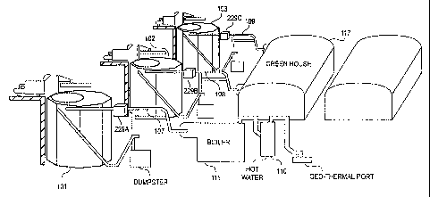
The complete system of the present invention can be understood by
referring to Figure 1, which shows a closed-loop waste gasification system
100.
Waste hauling trucks unload feed stock material either directly into batch
waste
gasification reactor chambers 101, 102, 103, as shown in Figure 9, or unload
the
feed stock at a tipping floor area 50, as shown by Figure 10, whereby a
variety of
conveyors 60 transport the feed stock to the gasification reactor chambers
101,
14
CA 02482557 2009-01-16
102, 103. Once in the gasification reactor chambers 101, 102, 103, the feed
stock
material undergoes gasification. Uncombusted heavy vapor fuel gas driven off
in
the reactor chambers 101, 102, 103 is evacuated by aspirator assemblies 229a,
229b, 229c through collection ducts 107, 108, 109 to the dedicated flare
assemblies 210a, 210b, 210c.
Radiant and convection heat generated in the flare assemblies 210a, 210b,
210c converge, and are absorbed by at least one heat recovery device, such as
a
primary heat recovery device 211, which may include, but is not limited to, a
steam boiler, heat exchanger, or any other heat sink. Each flare assembly
229a,
229b, 229c may be operably connected to both a single self-sustaining
gasification
reactor chamber 101, 102, 103 and to the primary heat exchanger 211, as
illustrated in Figure 1, whereby the flare assemblies 229a, 229b, 229c produce
a
hot combusted exhaust that is fed into a primary heat recovery device 211.
Alternatively, the dedicated flare assemblies 210a, 210b, 210c may be a sub-
component of, or built into, a common or a separate primary heat recovery
device
211, whereby, rather than receiving thermal energy in the form of hot
combusted
gas, the combustion of heavy vapor fuel gas is directly used to power or
operate
the primary heat recovery device 211.
As shown in Figure 9, in the preferred embodiment of the present
invention, the gasification reactor chambers 101, 102, 103 and their dedicated
flare
assemblies (not shown), the flare assemblies being similar to the flare
assemblies
210a, 210b, 210c illustrated in Figure 1, are operably connected to different
primary heat recovery devices. As illustrated, one gasification reactor
chamber
101 provides heavy vapor fuel gas for operating a boiler 111 and hot water
heater
110, while other gasification reactor chambers 102, 103 independently supply
heavy vapor fuel gas to support the operations of a greenhouse 117. Each
associated flare assembly then independently satisfies its combustion
requirements
CA 02482557 2009-01-16
for the attached heat recovery device. Alternatively, as shown in Figure 1,
the
multiple flare assemblies 210a, 210b, 210c may also be operably connected to a
common primary heat recovery device 211, whereby each individual flare
assembly 210a, 210b, 210c independently combusts heavy vapor fuel gas from its
dedicated reactor chamber 101, 102, 103 in accordance with the designed
combustion requirements of the common primary heat recovery device 211.
Furthermore, although Figure 1 illustrates flare assemblies 210a, 210b, 210c
as
separate components that are not part of the primary heat recovery device 211,
each flare assembly 210a, 210b, 210c may also be built into, or a subcomponent
of, the system's 100 primary heat recovery device 211.
Additional heat recovery devices, such as a secondary heat recovery device
212 may also use exhaust from the primary heat recovery device 211. In one
embodiment of the invention, the secondary heat recovery device 212 is a
reverse
chiller refrigeration system, the reverse chiller system being comprised of an
inlet,
a radiator, an induced draft fan, a sump, and an outlet. Hot exhaust is pumped
into
the radiator from the primary heat recovery device 211, the momentum for the
hot
exhaust being provided by the in-line induced draft fan that is preferably
located
on the back out-take side of the radiator loop. In the preferred embodiment of
the
present invention, exhaust from the primary heat recovery device 211 enters
the
reverse chiller at approximately 350 degrees Fahrenheit. Water within the
radiator
then begins to condense, and continues condensing as the exhaust gas is
reduced in
temperature to preferably 70 degrees Fahrenheit. The rapid cooling of the
exhaust
from the primary heat recovery device 211 causes particulates, such as HC 1
and
SO2, to condense out of the gas. Accumulated pollutants and condensate are
then
collected in a sump at the low point of the radiator and removed from the
system.
Cooled exhaust gas will then be piped back to the gasification reactor via an
additional induced draft fan, and directed to a plurality of cooling fins
within the
reactor chambers 101, 102, 103. The cooled exhaust is then used as a cooling
16
CA 02482557 2009-01-16
media, which thereby eliminates the need for an exhaust stack, as required by
incineration and pyrolysis operations. Alternatively, once conditions, such as
temperature and oxygen content, within the reactor chambers 101, 102, 103
reach
predetermined levels, cooled exhaust may be re-introduced into the
gasification
chamber through a plurality of process gas inlets and aid the gasification
procedure.
In the illustrated embodiment, once the at least one heat recovery device
has significantly cooled the exhaust gas, it becomes possible to avoid any
regulated air emissions by diverting the exhaust to an underground geothermal
field 113. Heat from the exhaust passing through the geothermal field 113 may
then heat surrounding surfaces, such as soil or a body of water, thereby
providing
heat to support a number of activities, such as, but not limited to, a
greenhouse 117
or an aquaculture bed.
The geothermal field 113 is forcibly vented by an induced draft fan 317 to
an absorber 115, such as a monolithic lime or sodium carbonate absorber, for
the
removal of at least a portion of criteria pollutants. For exainple, if the
feed stock
material contained plastics, or other substances which might cause the
formation
of either HCI or S02, the exhaust leaving the at least one heat recovery
device will
be diverted to a passive sodium carbonate absorber to reduce any potential for
excessive levels of these chemicals in the end recycled process gas product.
As a final step, at a juncture 148, the filtered gas is pulled from the system
and into an extractor 116 a carbon dioxide extractor 116 retrieves gaseous
carbon
dioxide for a carbon dioxide consumer. Oxygen produced by the consumption of
extracted carbon dioxide, such as the conversion of carbon dioxide into oxygen
by
vegetation, may be vented back into the system 100 via a return air line 118
to
17
CA 02482557 2009-01-16
provide recycled process gas or a cooling medium for the gasification reactor
chambers 101, 102, 103.
In another iteration of the design, a greenhouse 117, or some other
agricultural carbon dioxide dispersal system replaces the carbon dioxide
extractor
116. Carbon dioxide is then sequestered before the balance of the filtered
exhaust
stream is returned to the reactor chambers 101, 102, 103 via the return air
line 118
as recycled process gas.
Combustion Loop Detail
Figure 2 illustrates additional detail of the gasification system 100
combustion process loop. Feed stock material is fed into the gasification
chamber
101 through the primary access loading door 120, as shown in Figure 3B. The
primary access loading door 120 and any other residual removal ports are then
sealed, and all gasification process gas intake ports are closed. The
aspirator
assembly 229 then starts reducing the volume of ambient air within the reactor
chamber 101. Following this air purge, which typically for a system containing
50
tons of feed stock material may take 15 minutes, at least one heater that is
near the
base of the reactor chamber 101 is activated. In the preferred embodiment of
the
present invention, the heater may include, but is not limited to, a fuel-fired
burner
or an electric thermal radiant heat assembly.
Once the ambient temperature inside the reactor chamber 101 reaches a
predetermined temperature, the heater is turned off. For example, in a system
containing 50 tons of mixed feed stock, a predetermined temperature of 300
degrees Fahrenheit may be reached in approximately 35 minutes. In the
preferred
embodiment of the present invention, a pair of Type K thermocouples is used to
determine whether the average ambient temperature has reached the
18
CA 02482557 2009-01-16
predetermined limit. These thermocouples may be positioned in a variety of
locations, such as, but not limited to, below the grate, around the midsection
of the
reactor chamber 101, at the top of the reactor chamber 101, or in conjunction
with
additional thermocouples in any combination thereof.
As the temperature and oxygen level in the reactor chamber 101 reach
predetermined levels, a plurality of process gas inlets located below the
grate level
of the reactor chamber 101 are slowly opened. By controlling the flow of
process
gas, including outside ambient air and recycled process gas from the
extractor, the
plurality of process gas inlets act as valves to keep the average internal
temperature of the reactor chamber 101 within a predetermined range and
prevent
the incursion of ambient air, which may increase the oxygen level of the
process
air and cause combustion, from entering into the reactor chamber 101. In the
preferred embodiment of the present invention, this predetennined temperature
range is within approximately 350 and 750 degrees Fahrenheit, while the oxygen
level is 4% to 11% of ambient. These predetennined levels facilitate the
substochiometric combustion conditions that cause heavy vapor fuel gas to form
and rise to the top of the reactor chamber 101 via convection.
In the preferred embodiment of the present invention, the plurality of
process gas inlets may be opened by a common electric motor that is controlled
through the use of a process logic controller. Oxygen and temperature sensors
sample the interior environmental air and relay the information to the process
logic
controller. The process logic controller may also be connected to data
recorders
and digital display panels in the system control cabinet. Such sensors may be
located in a variety of positions, including, but not limited to, heavy vapor
fuel gas
evacuation ducts in the ceiling of the reactor and in a reinforced stainless
steel
cage located on the interior wall of the reactor chamber.
19
CA 02482557 2009-01-16
As the temperature inside the reactor chamber 101 continues to climb, the
ambient oxygen content within the chamber 101 drops. When the internal
temperature and oxygen level reach a predetermined level, such as, but not
limited
to, approximately five percent of ambient oxygen and 350 degrees Fahrenheit,
the
aspirator assembly 229 begins extracting heavy vapor fuel gas out from the
reactor
chamber 101 through an aspirator assembly 229.
The aspirator assembly 229 uses impelled ambient air passing through a
conduit coupling to create a negative back pressure in the reactor chamber 101
and
the gas siphon assembly 225. This negative pressure creates a suction force
that
draws heavy vapor fuel gas from the reactor chamber 101 into the gas siphon
assembly 225. In the preferred embodiment of the present invention, the gas
siphon assembly 225 extends into and out of the reactor chamber 101, as shown
in
Figure 5A. In the preferred embodiment, a portion of the gas siphon assembly
225
that extends into the reactor chamber 101 is perforated and mounted along the
ceiling of the reactor chamber 101. At least a portion of the gas siphon
assembly
225 outside of the reactor chamber 101 is insulated. Besides withdrawing heavy
vapor fuel from the reactor chamber 101, the aspirator assembly 229 also mixes
ambient air with the collected heavy vapor fuel gas, thereby creating a mixed
gas.
Heavy vapor fuel gas extracted from the reactor chamber 101 will
preferably enter the gas siphon assembly 225 at a temperature of approximately
800 degrees Fahrenheit. However, because the aspirator assembly 229 mixes the
hot heavy vapor fuel gas with ambient air, the mixed fuel gas released from
the
aspirator assembly 229 will preferably have a temperature of approximately 600
degrees Fahrenheit, and is delivered to the flare assembly 210 at a rate of
approximately 540 CFM.
CA 02482557 2009-01-16
The flare assembly 210 is operably connected to at least one burner 220
that initiates combustion of the mixed gas. In the preferred embodiment of the
present invention, the at least one burner 210 consists of, but is not limited
to, two
2 inch propane burners that utilize pilot igniters. Additionally, the
combustion
temperatures in the preferred embodiment are operated at approximately 1600
degrees Fahrenheit.
In processing 100 tons of MSW in accordance with the present invention,
in which the MSW has a heat value of 4290 Btu/hr, it is anticipated that the
flare
temperature will be 1857 degrees Fahrenheit, and will produce total gas output
of
47,903 lb/hr, a sensible heat content of 25,011,241 Btu/hr (ref. 77 degrees
Fahrenheit), and a latent heat content of 5,337,774 Btu/hr.
Unlike traditional gasification systems, rather than using an exhaust stack
to vent hot combusted gas into the atmosphere, or bottle the gas for ancillary
operations, heavy vapor fuel is utilized by at least one heat recovery device.
In the
preferred embodiment, a primary heat recovery device 211, a secondary heat
recovery device 212, and a geothermal field 213 recover heat entrained in the
combusted gas.
In the preferred embodiment, the primary heat recovery device 211 is
configured to operate on the power or heat generated by the combustion of the
heavy vapor fuel gas by the flare assembly 210. In such a design, the flare
assembly may be built into, or a subcomponent of, the primary heat recovery
device 211. Alternatively, hot exhaust produced by the combustion of the heavy
vapor fuel gas by the flare assembly 229 may be delivered to, and utilized by,
the
primary heat recovery device 211. Exhaust from the primary heat recovery
device
211 typically has a temperature in the range of 350 degrees to 500 degrees
Fahrenheit.
21
CA 02482557 2009-01-16
The secondary heat recovery device 212 operates on the combusted exhaust
provided by the primary heat recovery device 211. In the preferred embodiment,
the secondary heat recovery device 212 further cools the combusted exhaust to
the
range of 200 degrees to 300 degrees Fahrenheit.
In the preferred embodiment, exhausted combusted gas from the secondary
heat recovery device 212 is delivered to the geothermal field 213, which
provides
a final cooling stage. An induced draft fan 214 preferably provides momentum
for
combusted gas to pass through the geothermal field 213. The geothermal field
will
typically produce a final exhaust temperature of 60 degrees to 80 degrees
Fahrenheit, which are approximately ambient conditions. In one embodiment of
the invention, carbon dioxide separation may be provided at early stage by
separator 216 that is operably connected to the geothermal field 213.
An absorber 215, such as, but not limited to, a monolithic lime absorber,
then filters critical regulated pollutants, such as HC 1 from the cooled
combusted
gas. Filtered exhaust exiting the absorber 215 is typically comprised of water
dioxide and carbon dioxide. A carbon dioxide extractor 116, such as, but not
limited to, a Wittmann carbon dioxide extractor, is employed to remove the
carbon
dioxide molecules from the filtered exhaust. In an alternative embodiment, the
extractor 116 is replaced by a greenhouse 117, or by an agricultural carbon
dioxide
dispersion system, whereby carbon dioxide is sequestered from the filtered
exhaust. The remaining filtered gas is then re-directed to the reactor
chambers 101,
102, 103, where it is re-introduced into the gasification cycle as recycled
process
gas, and thereby eliminates the need for an exhaust stack.
Extracted carbon dioxide gas may be used for other industrial purposes, or
to support vegetation, such as replenishing the carbon content of soil of an
agricultural field by passing extracted carbon dioxide through a carbon
dioxide
22
CA 02482557 2009-01-16
dispersal system or venting it into a greenhouse. In an alternative embodiment
of
the present invention, oxygen that has been converted from extracted carbon
dioxide may be recaptured and reintroduced into the gasification chamber as a
cooling medium for the chambers 101, 102, 103, or as part of the ambient
process
gas intake.
Gasification Primary Vessel Detail
Figures 3 and 5 show details of the waste gasification reactor chamber 101
of the present invention. Depending on the quantity of required fuel gas, and
density of the selected feed stock, the capacity of the gasification reactor
chamber
101 can be configured to hold a wide range of feed stock material, such as,
but not
limited to, as little as one ton or as much as one thousand tons of feed stock
material.
Figures 5A and 5B illustrate the basic configuration of the gasification
reactor chamber 101 of the preferred embodiment. As shown in Figure 5A, the
gasification reactor chamber 101 incorporates a double walled configuration,
in
which the interior chamber 126 is sleeved inside the outer shell 127. While
the
interior chamber 126 of the present invention is capable of having a
rectangular,
square, or cylindrical configuration, the preferred embodiment of the present
invention has at least five side walls, such as an octagonal or hexagonal
shape, and
is a continuously welded container of 1/2 inch thick, 316 or 304 stainless
steel
plate or cast iron. In one embodiment of the invention, a reactor chamber 101
an
octagonal reactor chamber that is designed to hold approximately 50 tons of
feed
stock material will be approximately 24 feet tall and 8 feet wide on the
sides.
Additionally, at least one burner 220 is operably connected to the interior
chamber 126, the at least one burner 220 providing heat to elevate the
temperature
23
CA 02482557 2009-01-16
inside the interior chamber 126. In the preferred embodiment of the invention,
two
openings are positioned beneath grate level, each opening being operably
connected to at least one natural gas or LPG-bumer, thermal lance, electrical
resistance heat generator, or other heat generating device.
Figure 5D illustrates a cross sectional side view of the gasification reactor
chamber in accordance with one embodiment of the present invention. The outer
surface of the interior chamber 126 includes a plurality of aluminum
convective
cooling fins 130 that dissipate heat away from the surface of the interior
chamber
126. Between the cooling fins 130 and the interior surface of the outer shell
127 is
at least one layer of insulation 129. The preferred embodiment of the
invention
utilizes an insulative jacket that is comprised of two layers of insulation,
with the
first layer 77, which covers the cooling fins, being a 2 inch thick blanket of
ceramic fiber. On top of the ceramic fiber is second layer 78, the second
layer
being comprised of an 8 inch thick layer of mineral wool block, which is an
inexpensive and durable heat- dissipating industrial material that is commonly
used for covering hot pipes.
The preferred embodiment of the invention also includes vents 131 located
on the sides of outer shell 127, as illustrated in Figure 5B. Because of the
temperature gradient between the cooler outside ambient air and the elevated
temperatures of the gasification reactor chamber 101, these vents 131 allow
for
outside air to rise into the space between the interior chamber 126 and the
outer
shell 127, and through the at least one layer of insulation 129, thereby
providing
cooling air flow through the mineral wool. In the preferred embodiment of the
present invention, such vents 131 could allow for a sustainable external
temperature of approximately 100 degrees Fahrenheit.
24
CA 02482557 2009-01-16
When needed, ambient air and/or recycled process gas is supplied to the
gasification reactor chamber 101. Ambient air may be provided to the reactor
chamber 101 through a plurality of process gas inlets, as shown in Figures 3B,
3C,
and 5A. In the preferred embodiment of the present invention, each wall of the
interior chamber 126 has at least one process gas inlet 112. In the preferred
embodiment of the present invention, each process gas inlet 112 has a 6 inch
diameter. Furthermore, at least two of these process gas inlets 112 are
preferably
operably connected to a common air supply manifold 125. In the preferred
embodiment, the manifolds 125 are comprised of 8 inch diameter tubing that
circumscribes the outside diameter of the interior chamber 126, the tubing
having
a first end and a second end, the first end being connected to a variable
speed
blower that is located outside of the reactor chamber 101, and the second end
being completely occluded. Additionally, a damper is preferably operably
positioned between the blower and the manifold, the damper configured to
control
the introduction of the limited process gas necessary to maintain the
gasification
cycle and to prevent the inclusion of unwanted ambient air in the interior
chamber
126.
Recycled process gas may be returned to the gasification reactor chamber
101 via a return air line 118. In the preferred embodiment of the invention,
the
recycled process gas may be used as a cooling media for the reactor chamber
101,
in which the recycled process gas flows between the insulative jacket and the
outer
shell 127. Alternatively, the return air line 118 provides a path for the
controlled
introduction of the recycled process gas into the gasification cycle, the
return air
line being operably connected to the plurality of process gas inlets 112.
Figures 3A, 3B, and 3C illustrate the outer shell 127 of the preferred
embodiment. The outer shell 127 is preferably constructed from A36 hot rolled
structural shapes and steel sheet, that may be similar to painted metal ribbed
CA 02482557 2009-01-16
panels, and provides mechanical support for the loaded reactor vessel. The
outer
shell 126 may also provide attachment points for monitoring, ducting,
insulation,
and other gasification operating equipment.
Feed stock is loaded into the reactor chamber 101 through an access
loading door 120, as shown in Figure 3A, and placed on a grate 70, as
illustrated
in Figure 3D. The gasification reactor chamber 101 may also include an
additional
opening near the floor of the chamber that is just below the highest edge of
the
bottom grate, and which allows for access for maintenance and repairs. In the
preferred embodiment of the present invention, the maintenance opening is
bolted
and gasket into place.
Removal of residual solid waste after gasification is accomplished through
a disposal opening 119, and is preferably lead away from the reactor chamber
101
via a conveyor 321. The exact arrangement of the conveyor system is not
critical
and any arrangement for conveniently removing solid byproducts is acceptable
as
long as the reactor chamber 101 can be sealed off from outside ambient air
during
the gasification cycle. Furthermore, the grate 70, which supports feed stock
material within the reactor chamber 101 may have a sloped configuration that
is
designed to facilitate the movement of solid waste product remaining after the
gasification process towards the disposal opening 119, as illustrated in
Figure 3D.
Figure 3E illustrates another embodiment of the present invention, which
includes
at least one inclined surface beneath the grate 70 that tapers inward towards
the
disposal opening 119, the disposal opening 119 being located at the base of
the
reactor chamber 101. Adjacent to the disposal opening 119 is a slatted
discharge
conveyor. The slatted discharge conveyor is preferably positioned in a trench
in
the concrete floor and is configured to receive and remove any remaining
debris
from the reactor chamber 101 after the completion of the gasification cycle.
An air
26
CA 02482557 2009-01-16
lock at the exit point of the slatted discharge conveyor is used to prohibit
the
unwanted incursion of ambient air into the reactor chamber 101.
In the preferred embodiment of the present invention, both the disposal
opening 119 and the primary access loading door 120 are hydraulically
activated
doors that are formed from 1/8 inch thick type 304 stainless steel, and are
insulated with a ceramic blanket and/or mineral wool fiber. A seal insures an
air-
tight fit between the door and the top of the reactor.
Figures 3D and 3E also illustrate the perforated grate 70 within the interior
reactor chamber 126, in which the perforated grate 70 acts as a primary
reaction
zone. The perforations in the grate 70 are configured to allow the bottom
portion
of the feed stock material to be exposed to gasification process gas.
Furthermore,
rather than using a sloped grate 70 that is designed to facilitate movement of
the
debris remaining after the completion of the gasification cycle towards the
disposal door 119, as illustrated in Figure 3D, the perforations in the grate
70 may
be configured to allow any remaining debris to fall below the grate for
eventual
removal from the reactor chamber 101, as illustrated in Figure 3E. In such an
embodiment, interior chamber includes at least one inclined surface, the at
least
one inclined surface 132 having a first portion and a second portion. The
first
portion of the inclined surface 132 is operably connected to the bottom of the
interior chamber, and tapers inwards to the second portion. The second portion
is
operably positioned in proximity to the disposal opening 119.
The present invention increases the primary and secondary reaction zones
through the incorporation of at least one perforated conduit 75, as
illustrated in
Figures 3D, 3E, and 5A. In the preferred embodiment, the perforated conduit 75
extends from the base of the perforated grate 70 towards, but not reaching,
the
ceiling of the reactor chamber 101. As illustrated in Figure 5A, the at least
one
27
CA 02482557 2009-01-16
perforated conduit 75 is preferably positioned in proximity to the
intersection of
the reactor chamber walls, and extends outwards towards the center of the
interior
chamber 126. The plurality of process gas inlets 112 passing through the walls
of
the interior chamber 126 are positioned relative to the location of the at
least one
perforated conduit 75. The perforated conduit 75 then provides a passageway
that
permits process gas to travel in an upward direction along the perforated
conduit
75. This configuration prevents the flow of process gas from being occluded by
feed stock material covering the plurality of process gas inlets 112. These
perforations 76 are then configured to allow for the exposure of additional
feed
stock surface area to gasification process gas, with at least a portion of the
perforated conduit 75 adding to the total surface area of the primary reaction
zone,
and the remaining exposed surface area adding to the total surface area of the
secondary reaction zone. However, the at least one perforated conduit 75 may
be
also positioned at a variety of locations, including, but not limited to,
being offset
away from the walls and towards the center of the feed stock, at various
locations
along the walls of the reactor chamber 101, through the center of the feed
stock,
and all other positions that would be understood and appreciated by one of
ordinary skill in the art. In the preferred embodiment, the at least one
perforated
conduit having a one foot by one foot construction and extends to within four
feet
of the top of the interior chamber 126, with the top being sealed with a solid
cap.
The use of perforated conduits 75 and/or an inner linear 76 also allows the
gasification reactor chamber to have a column configuration that includes at
least
five sidewalls. This column configuration and perforated conduits 75 and/or an
inner linear 76 configuration eliminates the 50 ton capacity limitation of
prior art
gasification reactor chambers. Furthermore, feed stock material may be top
loaded
into the colunm configuration, and therefore eliminate the repose fill
problems
associated with side loading a rectangular reactor chamber configuration, and
allows feed stock material to be top loaded through the use of a conveyor.
28
CA 02482557 2009-01-16
Figure 5C illustrates an alternative embodiment of the gasification reactor
chamber 101, in which an inner liner 76 is placed within the interior chamber
126,
and preferably is position so as to leave a gap between the interior sidewalls
of the
interior chamber 126 and the inner liner 76, as illustrated in Figures 5C and
5D.
The inner liner 76, which may be constructed from heavy wire mesh, has a
plurality of perforations that permit the flow of gasification process gas to
the feed
stock material. In the preferred embodiment, the inner liner 76 is a 1 inch by
one
inch stainless steel mesh fabricated from 5/8 inch stainless steel wire and
positioned 2 to 4 inches away from interior surface of the interior chamber
126.
Process gas is then able to circulate in and around the feed stock material
along the
sides of the inner liner 76, thereby allowing the side surfaces of the feed
stock
material to become part of the primary reaction zone. Additionally, because
the
inner liner 76 physically contains the feed stock material, the walls of the
interior
chamber 126 do not have any mechanical contact with the feed stock material.
This lack of contact allows the walls of the interior chamber 126 to be
fabricated
from substantially thinner material, thereby further reducing the weight and
fabrication expenses of the reactor chamber 101.
The increased exposure of feed stock material to gasification process gas
significantly increases the sizes of the primary and secondary zones, which
allows
for a faster gasification procedure at lower temperatures. For example, prior
art
rectangular reactor chambers that are designed for 50 tons of feed stock
material
will typically have a primary reaction zone area of 120 square feet, and an
additional 800 square feet of secondary reaction zone at the uppermost surface
of
the waste zone, for a total primary and secondary reaction zone of 920 feet.
However, an octagonal reactor chamber of the present invention that is
designed to
hold the same 50 tons of feed stock material, and which includes eight
perforated
conduits 75, has a primary reaction zone of 498 feet at the sloped perforated
grate
70, plus an additional 384 square feet from at least the lower portion of the
29
CA 02482557 2009-01-16
perforated conduits 75, for a total primary reaction zone of 882 square feet.
As the
temperature of the reactor chamber 101 stabilizes, an additional 782 square
feet of
secondary reaction zone is created, which is comprised of 384 square feet from
at
least a portion of the perforated conduits 75, and 398 square feet from the
upper
surface area of the feed stock. The total primary and secondary reaction zone
surface area is therefore 1,664 square feet, roughly 1.78 times that of
conventional
rectangular reactors.
The addition of the inner lining 76 to the eight perforated conduits 75
described in the above-mentioned 50 ton octagonal reactor chamber increases
the
surface area of the primary reaction to 2,002 square feet. When added to the
384
square feet of the secondary reaction zone, which is created at the top of the
feed
stock material, the primary and secondary reaction zones provide a total feed
stock
reaction surface area of 2,386 square feet. Although Figure 5C illustrates the
inner
liner 76 being used in conjunction with at least one perforated conduit 75,
the liner
may also be configured to eliminate the need for the perforated conduits 75,
while
still preventing the plurality of process gas inlets from being occluded by
feed
stock material.
Because gasification cycle time is a function of surface exposure to the
process gas supply, an increase in the surface area of the primary and
secondary
reaction zones represents a significant reduction in the rate of reaction
necessary
for gasification, and thus reduces the cycle time required for a single charge
of
feed stock. Thus, for example, the maximum anticipated volume of heavy vapor
fuel gas produced from feed stock material in the present invention could be
reduced to less than 12 hours, instead of the 18 to 24 hour cycle times of
prior art
systems. By decreasing both the time and temperature required for the
gasification
of feed stock material, the present invention further eliminates the need to
rely on
multiple reactor chambers to meet system volume capacity requirements.
CA 02482557 2009-01-16
Furthermore, this configuration substantially reduces the external surface
temperature of the gasification reactor chamber 101 during operation, thereby
making the environment around the system safer for workers.
The lower operating temperature within the reactor of the present invention
also improves the ultimate air quality of the final system exhaust. Constant
cooling
of the reactor interior chamber 126 by convection helps stabilize the reactor
temperatures to as low as 750 degrees Fahrenheit. At this temperature level,
there
is insufficient thermal energy to create many of the complex chemical
reformation
reactions that occur in mass burn incinerators, some pyrolysis systems, some
high
temperature gasifiers, and plasma systems from the various materials that
comprise the feed stock material within the reactor. Depression of the optimum
operating temperature also inhibits the volatilization of most metals, thus
virtually
eliminating the metal content in exhaust air from the total system.
The simplified single gasification reactor chamber 101 of the present
invention also has significant financial benefits over large, multi-celled
fixed
systems, in tenns of flexibility, portability, and economics of installation,
operation, and maintenance. Faster gasification cycles at lower temperatures
permit the gasification reactor chamber 101 to be fabricated from lighter and
less
expansive material. In comparison to prior art systems, the lightness of both
the
gauge of the material and insulative layers produces a significant reduction
in the
overall weight of the system. This reduction in weight translates into both
lower
material and installation expenses. Furthennore, the time required for
fabricating
and installing such a system is greatly reduced by the elimination of
refractory
materials and associated refractory hanger installation. The absence of the
weight
attributable to refractory material also allows for the use of lighter
structural steel
members. Repair and maintenance profiles for a stainless steel system are far
superior to hot rolled steel structures that are painted. Additionally, the
relative
31
CA 02482557 2009-01-16
small size of the present invention allows a single gasification system to be
economically and efficiently sited at the location of the fuel demand, such as
the
location of the at least one heat recovery device. These benefits allow a
single
reactor supplying energy from this alternative fuel-generating reactor to be
economically and efficiently sited at the location of the fuel demand.
Gas Extraction Details
Figure 6 illustrates details of the gas extraction assembly of the present
invention. The extraction scheme includes an aspirator assembly 229 that
replaces
the air-mixing chamber of the prior art. The aspirator assembly 229 is capable
of
both evenly withdrawing heavy vapor fuel gas from the interior chamber 126 and
completely mixing impelled ambient air with the extracted oxygen-deficient
heavy
vapor fuel gas, thereby creating an oxidized mixed gas. The aspirator assembly
229 can also provide transport of the mixed gas over greater distances than
conventional methods, thereby making the whole system more adaptable than
current designs, especially for multiple cell systems.
A damper assembly, which is the norm in prior art gasification systems, has
been eliminated in the present invention in favor of employing a variable
speed
motor 227 as the driving device for extracting gas from the reactor chamber
101.
The motor 227 forces ambient air through a second passageway 228 and into an
impeller 224, which subsequently supplies impelled air through a passageway
223
and into a conduit coupling 230. In the preferred embodiment of the invention,
a
hp motor 227 is mounted approximately 7 feet above floor level, the motor 229
being operably connected to a shutoff valve that is located thirty feet above
floor
level.
32
CA 02482557 2009-01-16
Figure 7 illustrates the preferred embodiment of the conduit coupling 230.
which is shown as having a"Y" configuration, but may have a nuinber of
configurations, including a "T" shape, as would be understood and appreciated
by
one of ordinary skill in the art. In the preferred embodiment, the conduit
coupling
230 readily available from an industrial supply source. The conduit coupling
230
is comprised of a first leg 141, a second leg 142, and a stem 143. High
velocity
impelled air passing along the first leg 141 and through the stem 143 of the
conduit coupling 230 creates a suction force in the second leg 142, the
attached
single manifold pipe 226, and the gas siphon assembly 225, thereby creating a
slight negative pressure in the interior chamber 126. As heavy vapor fuel gas
is
produced and rises to the top of the interior chamber 126, the suction force
created
in the conduit coupling 230 draws the heavy vapor fuel gas into the portion of
the
gas siphon assembly 225 that extends inside the interior chamber 126, as
illustrated in Figure 5A. The gas siphon assembly 225 is sized according to
the
type of feed stock material and designed for the capacity of the chamber 101.
In
the preferred embodiment of the invention, the gas siphon assembly 225 is
comprised of 3 inch diameter 316 stainless steel, schedule 40 piping. The
pipes are
preferably mounted along the ceiling of interior chamber 126, and terminate at
a
single manifold pipe 226, with at least a portion of the piping inside the
reactor
chamber 101 being perforated so as to permit heavy vapor fuel gas to pass into
the
gas siphon assembly 225.
The suction force created by the aspirator assembly 229 allows for smooth
and even extraction of heavy vapor fuel gases from the interior chamber 126,
and
increases the quantity of extracted heavy vapor fuel gas. This even and smooth
extraction provides a number of benefits, including: causing the gasification
process to work with less fluctuation in gas volume removal from the reactor
chamber 101 as the gasification process works its way through the raw feed
stock
material; reduces the total primary gasification process cycle time; and
supplies a
33
CA 02482557 2009-01-16
more homogenous and regulated flow of heavy vapor fuel gas product to the
ultimate burner system that will combust the gas in the employed heat recovery
strategy of the present invention.
Once the heavy vapor fuel gas reaches the conduit coupling 230, the influx
of the hot heavy vapor fuel gas into the cold impelled ambient air stream,
creates
considerable turbulence in the down-stream pipe 231. This turbulence is more
than
adequate to accomplish air mixing, and will add ambient air volume to the
heavy
vapor fuel gas that is approximately equal to that produced in conventional
air-
mixing chambers.
The aspirator assembly 229 also overcomes problems associated with
accelerating mixed gas for use in ancillary systems. In the preferred
embodiment,
the gas siphon assembly 225, single manifold pipe 226, passageway 223, conduit
coupling 230, and downstream pipe 231 are constructed from small diameter
tubing, which, in conjunction with the motor 227, increases both the velocity
and
turbulence of the passing ambient air and heavy vapor fuel gas. As compared to
the mixing obtained through conventional prior art methods, the increased
velocity
and turbulence created by the present invention significantly contributes to
increasing the mixing of the gases, which improves the completeness of the
combustion event.
This accelerated velocity may also provide back pressure to the supply
lines, which allows for the proper functioning of attached heat recovery
devices. In
some instances, this higher velocity delivery makes the heat recovery device
more
efficient. Additionally, unlike prior art induced draft systems, the increased
mixed
gas velocity allows the invention to operate equipment that requires higher
positive gas input pressures, such as common bottoming cycle electrical power
generation turbines, boilers, carburetors, and other fuel consuming devices
that
34
CA 02482557 2009-01-16
require a given amount of supply line gas pressure in order to function
properly.
Unlike the current invention, prior art designs were typically unable to
satisfy such
positive pressure requirements, either because of the inability to pressurize
the gas
because of dependence on a natural draft-driven processes or because of
problems
and expense associated with the application of high temperature, in-line,
induced
draft fans.
Furthermore, process efficiency in gasification is directly related to the
ability to control various functions through equipment sub-sets in the
gasification
process. For instance, rather than provide finite control of the oxidation of
the fuel
gas, prior art damper assemblies typically guess at the amount of flow volume
moving through the damper valve body. Unlike the prior art however, the vacuum
power and mixing air percentage of the aspirator assembly 229 of the present
invention can undergo a wide range of adjustment through the modification of
the
ducting size for both the evacuated heavy vapor fuel gas and the ambient air
intake
line. Further refmements in air mix and flow can be achieved by varying the
speed
of the impeller 224. Therefore, elimination of the damper assembly affords the
present invention finite control over the extraction rate of the heavy vapor
fuel gas
from the reactor chamber 101 and the mixing event, and affords direct control
over
the exact flow volume through the system. Additionally, functions of the
aspirator
assembly 229 may be even more accurately controlled through the use of process
control logic. These improvements allow for a finite level of process control
which
has not been possible in prior art natural draft systems.
The gasification reactor chamber described herein simplifies prior designs
and is a significantly less costly assembly, providing both a smaller space
requirement for such equipment and fewer parts than are represented in prior
art
systems. The size of the aspirator assembly 229 may be up to 90% smaller than
a
conventional air-mixing chamber, which dramatically decreases fabrication
costs,
CA 02482557 2009-01-16
and installation time. The elimination of a centralized gas collection duct,
which is
common to most prior art waste gasification systems, makes not only the entire
configuration of multiple gasification reactor chambers at a given facility
more
flexible, but also makes a multi- cell configuration simpler and less
expensive to
operate. Since there is no longer reliance on the central collection duct, the
gasification vessels can be arranged independently, or along different
vertical
planes than previous designs allowed. Furthermore, the flexibility of the
present
invention does not suffer from the prior art's cumbersome and difficult
methods of
moving the heavy vapor fuel gas from its point of formation to the point of
combustion.
Heavy Vapor Fuel Gas Flare Assembly
The single flare assembly of the prior art is usually a cylinder,
approximately 6 feet in interior diameter, and is made of a spun ceramic fiber
or
refractory casting liner that is position inside a steel exterior jacket.
Piercing the
sides of this assembly along alternating left and right ports are four to
eight pilot
igniters. These igniters provide an open flame for the purpose of facilitating
the
combustion of the incoming mixed gasses. The gasification system of U. S. Pat.
No. 6,439,135 utilizes a single flare assembly wherein the heavy vapor fuel
gas
from multiple reactor chambers converges for combustion, and in which the
combusted exhaust is typically subsequently vented into the atmosphere via an
exhaust stack. The present invention incorporates a dedicated flare assembly
210a,
210b, 210c for each reactor chamber 101, 102, 103, as illustrated in Figure 1.
Figure 4 illustrates the preferred embodiment of the flare assembly 210.
The flare assembly is comprised of a targeting nozzle 243, thermal insulation
241,
a housing 240, and at least one burner 220. In the preferred embodiment, the
targeting nozzle 243 has a conical funnel configuration that is constructed
from
36
CA 02482557 2009-01-16
cast ceramic and is enclosed in a stainless steel housing 240. The conical
funnel
configuration of the targeting nozzle 243 is configured to restrict the
incoming
flow of mixed gas 239 from the aspirator assembly 229 into a combustion focus
point 242. The conical funnel design of the targeting nozzle 237 supplements
the
mixing of the heavy vapor fuel gas and ambient air received from the aspirator
assembly 229, thereby further improving the combustibility of the mixed gas
239.
Additionally, the conical design of the targeting nozzle 237 accelerates the
velocity of the mixed gas through the nozzle. Immediately following the nozzle
tip
243 is at least one burner 220 that provides an ignition spark or raw flame to
ignite
the incoming mixed gas. In the preferred embodiment, the at least one burner
220
is comprised of two MaxonTM KinemaxTM 2 inch diameter burners.
The flare assembly 210 of the present invention has a number of benefits.
The number of igniter burners 220 required to adequately combust the mixed gas
is reduced. Reduction in the number of igniter burners 220 substantially
reduces
the consumption of supplemental fuel by the system. Also, the configuration of
the
targeting nozzle 237 offers better control for mixed gas flaring, and can also
be
used as an injection point for the processing of waste oil, paints, or other
volatile
liquids. The flare assembly 210 is also much smaller than conventional flares.
This
saves on fabrication and installation expenses, and reduces the overall size
of the
system.
Primary and Secondary Heat Recovery Device
Unlike traditional gasification systems, rather than use an exhaust stack to
vent the combusted gas into the atmosphere, or bottle the gas for ancillary
operations, heat is recovered from the flare assembly 210 by at least one heat
recovery device. In the preferred embodiment of the present invention, a
primary
heat recovery device 211 utilizes the combustion of the mixed gas, thereby
relying
37
CA 02482557 2009-01-16
on the fuel content of the heavy vapor fuel gas for operation. In such a
device, the
flare assembly may be built into, or be a sub-component of, the primary heat
recovery device 211. Alternatively, the primary heat recovery device may
receive
hot combusted exhaust gas from the flare assembly 210, as illustrated in
Figure 2.
These combusted gases may be directly supplied as the primary fuel source for
powering or heating primary heat recovery devices 211 such as, but not limited
to,
hot water heaters, boilers, refrigeration systems, dryers, omnivorous
fuel/internal
combustion engines, and turbines. Such use of heavy vapor fuel gases would
provide an alternative to the expense and conservation issues associated with
the
production, supply, and consumption of fossil fuels for powering such above-
mentioned devices. .
In the preferred embodiment, exhaust from the primary heat recovery
device 211 typically has a temperature in the range of 350 degrees to 500
degrees
Fahrenheit. A secondary heat recovery device 212 may be utilized to further to
recapture and reutilize the thennal energy entrained in the exhaust from the
primary heat recovery device 211, and via subsequent use, provide a further
cooled exhaust that preferably has a temperature in the range of 200 degrees
to
300 degrees Fahrenheit.
"Closed-Loop" Geothermal Heat Rejection Field
In one embodiment of the present invention, the closed-loop system
includes a geothennal field 113 that utilizes the entrained hot air exhaust
from the
primary or secondary heat recovery devices 211, 212. The geothermal field 113
provides a very low cost and maintenance-free system for final thermal energy
recovery. This geothermal field 113 also provides a no-operating cost method
of
reducing exhaust temperatures to meet intake requirements of emission
absorbers
115 and carbon dioxide extractors 116.
38
CA 02482557 2009-01-16
Figure 8 illustrates operation of one embodiment of the geothermal field
113. An induced draft fan 317 provides momentum for intake exhaust 310 from a
primary and/or secondary heat recovery device 211, 211 flow through both a
subsurface manifold piping system 315 and a geothermal loop 114. The
subsurface
manifold piping system 315 may be located underground or beneath a body of
water, and is comprised of inlet piping 316 and ventilation tubing 318.
As the hot air exhaust travels through the geothermal loop 114, it loses heat
through natural convection to the surrounding surfaces.. The length of the
field is
adjusted relative to the total tons of feed stock material being gasified per
day. For
example, 1,200 feet of piping in a geothermal loop 114 is adequate for systems
up
to, and including, 100 tons of feed stock per day, while a system of 200 tons
would require approximately 2,600 feet of tubing in the field. Furthermore, a
manifold piping system 315 that is comprised of four PVC inlet pipes 316
located
six feet below ground or water, and twelve inch diameter ventilation tubing
318,
can reduce an intake exhaust 310 heat of 500 degrees Fahrenheit to
approximately
200 degrees Fahrenheit.
When the geothermal loop 114 is placed under a greenhouse 117, it warms
surrounding soil, which transfers heat to the greenhouse. Ventilation fans may
then distribute heat throughout the greenhouse. In winter months, heat
provided
from the geothermal field 113 is sufficient to maintain environmental
temperatures
within growing limits, with only minimal supplemental heat needed on the
coldest
days. This may serve to significantly reduce wintertime costs of greenhouse
operations.
Furthermore, as previously discussed, the use of a greenhouse 117, or other
vegetative supporting system, also allows for the option of venting extracted
carbon dioxide from the extractor 116 to the greenhouse via piping 311.
39
CA 02482557 2009-01-16
Alternatively, as will be discussed hereinafter, the greenhouse 117 or other
vegetative system, may also replace the extractor 116, and be used to
sequester
carbon dioxide out from the filtered exhaust produced by the absorber 115.
Emission Controls
While the formation of noxious pollutants such as HC 1 and NOx is greatly
reduced in waste gasification processes, measurable quantities of the
pollutants
may still persist in the exhaust stream from time to time. To handle these
residual
pollutants, one embodiment of the invention includes an absorber 115, such as,
but
not limited to, a monolithic lime absorber. An absorber 115 such as a
monolithic
lime absorber absorbs HCl molecules from exhaust gas that is passed through
and
around it, thereby reducing the HC 1 concentration in the gas that is
eventually
returned to the chamber reactor 101. Alternatively, pollutants may be removed
by
passing the exhaust stream through a chilled radiator, whereby the pollutants
are
collected and condensed in water vapor.
When the filtered gas leaves the absorber 115, it is basically comprised of
water vapor, oxygen, hydrogen, nitrogen, carbon dioxide, and minimal trace
elements. At juncture 148, as shown in Figure 1, the filtered gas is pulled
from the
system and into an extractor 116, such as a Wittmann carbon dioxide extractor,
which removes the carbon dioxide molecules from the filtered gas. In the
absence
of an extractor 116, the cooled filtered exhaust may be vented into a
greenhouse
117, where vegetation converts the carbon dioxide of the filtered gas into
oxygen.
Alternatively, the filtered gas may be delivered to a carbon dioxide dispersal
system, as previously discussed. The resulting recycled process gas is then
mainly
comprised of water vapor and air that is delivered through a return line 118
and
manifold system back to the gasification reactor chambers 101, 102, 103 for
use in
CA 02482557 2009-01-16
the gasification process. Alternatively, the recycled process gas may be as a
cooling media for the reactor chamber 101.
The now cooled filtered exhaust also represents a significant source for
clean carbon dioxide. Depending on the size of the gasification system, carbon
dioxide extraction could provide environmental and economic advantages. For
example, should the gasification system be used to provide energy for a
greenhouse operation, as shown in Figure 11, piping 311 from the system 100
may
deliver and vent accumulated carbon dioxide for facilitating plant growth.
Properly selected greenhouse plants could easily consume all of the extracted
carbon dioxide in a reasonable time, thereby allowing the present invention to
emit
zero carbon dioxide emission from the disposal of MSW feed stock. Current
research indicates that increasing the Carbon dioxide level in a greenhouse
117
from ambient to as much as 1,500 ppm can increase the productivity of
tomatoes,
green peppers and lettuce by as much as 35%. Alternatively, as illustrated in
Figure 12, extracted carbon dioxide may be vented in a carbon dioxide
dispersal
system 400, in which carbon dioxide is passed through distribution chambers
410
located beneath, among other things, porous fill materials 411, filter fabric
412,
topsoil 413, and vegetation 413. In addition to the vegetation converting the
dispersed carbon dioxide into oxygen, released carbon dioxide also replenishes
the
carbon content of soil.
The foregoing system provides a low cost, closed-loop MSW gasification
system with that allows for complete material recovery and recycling of
metals,
glass, minerals and salts. Furthermore, the present invention may efficiently
recapture expended thermal energy while preventing overt discharge of air,
solids,
or waste water from the disposal of solid waste materials.
41
CA 02482557 2009-01-16
While the present invention has been illustrated in some detail according to
the preferred embodiment shown in the foregoing drawings and descriptions, it
will be understood that the invention is not limited thereto, since
modifications
may be made by those skilled in the art, particularly in light of the
foregoing
teaching. It is therefore contemplated by the appended claims to cover such
modifications that incorporate those features that come within the spirit and
scope
of the invention.
42