Note: Descriptions are shown in the official language in which they were submitted.
CA 02482605 2004-09-27
Commode Safety Frame
~'TELD CF TfiE r.'l3~lENTIt~N
jo~0~j This invention generalJ.y relates to persona, care
products and, mare particularly, to toilet ar commode safetx
f ram~a .
BACKGRt7UND OF THS Ti~V'ENT~'ON
j00027 safety frames provide assistance when entering,
leaving ox using commodes ar toilets. They typica~.ly
provyde one or more handle portions that al~.ow far grasping
by a user wk~.en entering, us~.ng, or leaving a. commode. One
such safety fzame is the Invaaare'~ Toilet Safety k'rame,
model no. x.392. These safety frames are typieal.ly
fabricated Pram circu7.ar tube constructions that axe easy to
assemble and cost-effective. ~'e~crerthe7.ess, there is a
desire for improved construction and fabrication of safety
frames .
SUMMARY OF TIDE I~VENT'If?N
j0003~ According to one embodiment, a commode safety
frame is provided. The safety frame includes, for example,
first arid second side fxarnes and first and second safety
bracket rails. Each side frame ~.ncludes a circular tube
portion that transitions to a first non-circular tube
portion and at least one aperture disposed substantially in
the muddle of the vertical ?ength of the first non-circular
portion. Each safety bracket rail is ~.n releasable
communication with the first and second side frames,
respectively, each includes a circular tube portion that
transitions to a second non-circular tube portion and at
least ana biased decent protruding from a wall of the second
1
CA 02482605 2004-09-27
non-circular tube portion and disposed substantially in the
middle of a vertical length of the second non-circular
portion.
(0003 BRTE1= DESCRxPTZON OF THE DRAwINGB
LnO~~J zn the accompanying drawings which are
incorporated in and constitute a part of the specification,
embodiments of the invention are illustrated, which together
with a general desarzptian of the invention given abo~re and
the detai~.ed description given be7.owp serve to example the
principles of this invention.
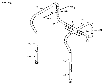
L00061 Figure 1 a.s an ~:xploded perspective of one
embodiment of a commode safety frame.
[0007 Figure 2 is an assembled perspective of the
embodiment of Figure 1.
I0008J Figure 3 is a (rant elevation view of the
embodiment of Figuxes ~ and ~.
[0009] Figure ~ is a rear elevation view of the
embodiment of figures ~. and Z.
[QO10J Figure 5 as a left side ele~ration view of the
embodiment of Figuren 1 and 2.
[04117 Figure 6 is a top p2an view of the embodiment of
Figures 1 and ~.
[00121 Figure '7 is a bottom plan view of the embodiment
of Figures 1 and 2.
[Q0137 Figure 8 is a cxass-section view taken along
section line 8-8 of Figure 2.
[0013 Figures 9 and 10 are a3.te~rnate embodiments of the
cross-section view of Figure B.
CA 02482605 2004-09-27
[OO15~ F'iguxe ~.1 is a second ~mbod~.ment with optional arm
xests or handgrips x.100 and 5.x.02.
DETAILED DESCRIPTTON OF' Tf~LtISTRATE1~ EMHOAIMEi3T
j0016] Referring now to Figures 1-°7, one embodiment 100
of a commt~de safety frame is illustrated. The safety frame
inoludes first and second side frames ~.OZ and 14, safety
bracket 222 with mounting plate 3.~~, safety brac~tet rails
I~.4 and 118, ana extendable J.egs x.26 and 128. As shown, the
various components are primari~.y made of tubu~.ar
construction. Side frame 1D2 includes a non-cixcular tube
portion 106 az~d side frame lab includes a non-circular tube
portion 1.08. In the .pr~s~nt emboda.ment, non-circular tube
portions 106 and 108 are square or rectangular in cross-
section and include at 7~eas'~ one aperture 130 and 134 in a
face thereof _ Side frames 1.0z and x.04 alsa i.r~c3.ude circular
portions X10 and x12, respectively, which are received
within the tubular legs 126 a.nd 128.
[04177 Safety bracket rails 114 and 118 also indlude a
non-circular tube portion 116 and x.20, respect~.vely. Zn
th~.s embodiment, non-circular tube portxoris lab and x.30 aze
also of square or rectangular crass-section and include a
biased pa.n or detent 136 protruding from. the face thereof.
The biasing can by any convention means including level
springs or coil sprir_gs.
LDD1$I In operation, the non-circular tube portions 106
and 116 matingly connect so as to affix the side frame 102
to the safety bracket rail. 1~.4,, wh~.ch is u7.t~.mately affixed
to the safety brac)teG x.7.2. The mating arrangement is such
that non-circular tube portion 1~.6 is dimensioned so as to
be able to be inserted within nQn-ci,rcu~,ar tube portion x.46.
The two Components are reZeasabl~r ~ affixed together when pin .
3
CA 02482605 2004-09-27
or decent x.32 co-locates with aperture ~.~0. The ad~rantage
provided by configured portions 106 and 116 as being non-
circular in cxose~seetion is that the mating connectian is
less prone to rvtat~.an and provides a more secuze and
reliable connection between the side frame lOZ and the
safety bracket avail 114. Once connected, to separate the
side frame 142 from the safety bracket 114, pin or decent
x.32 ~.s depressed thereby .withdrawing it from aperture 130,
which al~.ows the: two components to be separated. Side frame
~.0~ and safety bracket ra~.l 118 are si.mi~.arly eonneGted.
Figure Z illustrates the components of thg commode safety
frame 100 in the assemb~.ed state.
(00197 P~.ns ar decants 13~ and 136 are preferably located
in the middle or center of non-circular portion 116 and 1,~0
vertical length, In this regard, safety brackets x.14 and
218 are general~.y of circular tube construction, which
trans~.tion to a non-circular tube construction at portions
X16 and x.20. ~Ton~circular tube portions 116 and 12th have a
vertica3 length that is substantially the entire vertical
component of safety bracket rails 114 and 116, respectively,
except for a small bend which connects non--circular portions
116 and Z20 to the bodies of safety bxacket rails 114 and
118.
00020, Simi~.arly, side frames 102 and 104 axe generally
of circular tube construction and transita.on to a non
circular tube construction at portions 106 and 108. Non
circular tube portions 106 and 108 have a vertical Length
that xs substarit3ally the entire vextiaal component of the
connection to safety bracket raa.ls 114 and 116,
respectively, except for a sma'!1 bend which connects non
circular portions 16 and 108 to their respective side
frames. Apertures 130 and ~.3~ are a:~so preferably located
4
CA 02482605 2004-09-27
in the middle or center of non-ci,roular portion 116 and 120
vertical length.
000211 Referring nave to Figure 4, legs 1~6 and 128
include a plurality of apertures 40~. Apertures 402 are
used in combination a biased gin or decent 40~ to set the
height adjustment of the safety frame. Tn this regard, the
height is fixed when pin or decent g04 enters any one of
apertures 404. Depressa.on of pin or d,etent 404 causes the
pin or decent 4U4 to be withdrawn tram the aperture 404 so
that legs 1~6 and 128 can be vertically adjusted until the
proper safety frame height is achieved. Pin or decent .404
is then (fixed this height by once again entering the proper
aperture 404. Tt should also be noted that non-circu~.ar
portions 106 and 108 can inc~.ude a plurality of apertures
similar to those shaven in legs 126 and 128.
[0022) illustrated in Figure 8 is a oross-sectional. view
taken along section line 8-8 of Figure 2. As described
earlier, non~ciroular portion x.15 is sized and dimensioned
so that it can be inserted into non-cixcular port~.on x06,
As shown in the illustrated embadi~nent, the corners of the
generally square cross-section of portions 106 and 115 do
not allow any substantive rotation o~ the portions relative
to each other. Similar results can be achieved by an non
oircu~.ar arose-section, for example, Figures 9 and to
illustrate that the cross-sections for portions 106 and 116
can be generally triangular tFigure 9) or elliptical tFigure
10). Other polygonal cross-sectional ,shapes may also be
chosen.
[00231 Furthermore, the outer wa.l~.s or surfaces of
portions 106 and lOB need not be the same general. cross-
sectional shape as its ~.nner wa~.Is or surfaces because th~;se
CA 02482605 2004-09-27
outer walls or surfaces do not contribute to the non-
rotational configuration. Simi7.axly, the inxrex walls or
surfaces of portion 1.~.G and ~.~0 need not be the same general
cross-sectional shape as their outer walls ox surfaces
because these izznex walls or surfaces da nt~t contribute to
the non-rotatiana7. configuration.
L00247 While the pxesent invention has been illustrated
by the descriptaon of embodiments thereof, and while the
embodiments have been described in considerable detail, it
is not the intention of the applicant to restrict or in any
v~ay limit the scope of the appended c3.aims to such deta~.l.
Additional advantages and modification$ will readily appear
to thane skilled in the art. For example, The connections
between safety bracket 122 and ~.ts rails lI~ and 128 fan be
configured i.n the same mannex as that between side frames
102 and X04 and rails 1~.4 and 17.8. Therefore, the
invention, in its broader aspects, is not limited to the
specific details, the representative apparatus, and
illustxative examples shown and described. AccordingJ.y,
departures can be made frdrn such details without departing
from the spixit or scope of the applicant's general
inventive concept.
6