Note: Descriptions are shown in the official language in which they were submitted.
CA 02482880 2004-10-13
WO 03/086537 PCT/IB03/01190
Title: DEFIBRILLATION SYSTEM AND METHOD DESIGNED FOR RAPID ATTACHMENT
The present invention relates to equipments used in the electrical treatment
and monitoring of human bodies. More specifically, the present invention
relates to a
defibrillator using impedance-compensated defibrillation pulses to apply
treatment by contact
with the surface of a patient's skin, which is most conveniently accessible to
the rescuer.
Sudden cardiac arrest is often caused by ventricular fibrillation (VF) in
which
abnormal and very fast electrical activity occurs in the heart. During VF, the
heart cannot
pump blood effectively as it causes the individual muscle fibers within the
heart to contract in
an unsynchronized way. In treating victims of cardiac arrest with a
defibrillator, it is
important that the treatment be performed very rapidly as their chances of
surviving the
cardiac arrest decrease drastically over time following the cardiac arrest.
Studies have shown
that defibrillation shocks delivered within one minute after VF achieve up to
100% survival
rate. However, the survival rate falls to approximately 30% if 6 minutes
elapse before the
1 S defibrillation shock is delivered. Beyond 12 minutes, the survival rate is
almost zero.
Therefore, a quick response to cardiac arrest in administering a
defibrillation shock at the
rescue scene is critical.
Medical equipment manufacturers have developed Automated Electronic
Defibrillators (AEDs) to provide early defibrillation. AEDs deliver a high-
amplitude current
pulse, waveform, or shock to the heart in order to restore the patient's heart
rhythm to a
normal level. AEDs are widely deployed in both medical and non-medical
settings, including
private residences, public buildings, public transportation vehicles,
airplanes, businesses, etc.
AEDs are equipped with a pair of electrodes to deliver a series of shocks to a
patient as
needed. An electrode may include a conductive foil layer that resides upon a
conductive
adhesive layer, a lead wire electrically connected to the conductive foil
layer to the AED, and
an insulation layer for covering the conductive foil layer. The adhesive layer
serves to
physically and electrically displace the conductive foil layer to a patient's
skin. Electrodes
tend to deteriorate in time; thus, it is necessary to know their operating
condition when they
are used in a life-threatening situation. To this end, AEDs rely on a release
liner with multiple
CA 02482880 2004-10-13
WO 03/086537 PCT/IB03/01190
2
openings to determine whether the electrodes are in a proper operating
condition. When
manufacturing electrodes, new electrodes are detachably mounted on a release
liner in a
package. Prior to use, an impedance is measured through the release layer
disposed between a
pair of electrodes; if the measurement is higher than the threshold impedance,
the electrode is
S considered to be damaged, deteriorated, unfit for use.
Fig. 1 depicts the conventional AED 10 being applied to a cardiac arrest
victim 2 by a rescuer 4. As shown in Fig. 1, a pair of defibrillation
electrodes 12 and is placed
on anterior-anterior (AA) positions on the victim's torso. The rescuer selects
different sizes of
electrodes 12 for defibrillating adults and children. A main drawback of the
conventional
AED 10 is that it requires time-consuming steps in the deployment and use of a
defibrillator.
First, the placement of electrodes 12 necessitates removing clothes from an
unconscious
patient 2, sometimes requiring the use of a scissors 8 or knife in order to
gain access to the
desired location on the torso of the patient 2. Removing clothes causes a
longer delay for the
patient 2 in waiting for the defibrillating shock. In a highly stressful
emergency situation,
inexperienced or infrequent operators of the AED 10 are often reluctant or do
not
aggressively destroy the clothing on an unconscious stranger to expose the
recommended
attachment areas, and further slow the rescue attempt. In addition, some
victims of cardiac
arrest require removal of chest hair with a razor 6 to gain access to the
attachment areas,
which further delays the life-saving shock treatment, thus delaying and
reducing the chances
of a successful rescue attempt. Moreover, even after gaining access to and
attaching the
defibrillation electrodes 12 by the trained rescuers of the AED 10, the
delivery of the
defibrillation shock often fails because the rescuers inadvertently fail to
apply the electrode
pads correctly, thus missing the heart. The placement of the electrodes is
then repeated,
which is undesirable in the course of administering the defibrillating shock
Accordingly, there is a need for an improved defibrillator that is easy to use
and that enables a minimally trained user to easily, rapidly, and effectively
deploy the
defibrillator to treat the patient, with no or minimal clothing and hair
removal.
The present invention is directed to a method and system for quickly and
accurately applying the defibrillating shock to a victim of sudden cardiac
arrest.
According to an aspect of the invention, the apparatus may include a pair of
electrodes having an opening adapted to make electrical contact with a
patient, where one
electrode is disposed on a neck region of the patient and the other electrode
is disposed on the
CA 02482880 2004-10-13
WO 03/086537 PCT/IB03/01190
patient's body; a switch coupled to the pair of electrodes; an energy storage
for providing a
plurality of energy level outputs across the electrodes to the patient; and, a
controller coupled
to the switch and the energy storage for determining the need to apply the
defibrillation shock
to the patient and for determining the desired energy level output based on a
patient
impedance. The electrodes are coupled to an ECG front end for obtaining the
patient
impedance. The apparatus may further include a voltage charger coupled to the
energy
storage for charging a plurality of capacitors therein; a power source for
supplying electrical
power to the voltage charger; a timer associated with the controller; and, an
LCD display.
The energy storage may include a plurality of capacitors and a plurality of
resistors that are
arranged in series or parallel arrangement, or a combination of series and
parallel
arrangement. The defibrillation shock may be an impedance-compensated
defibrillation
shock that can be generated by setting the switch according to one of the
energy level outputs
in response to the patient impedance. Furthermore, the defibrillation shock
may comprise one
of monophasic, biphasic, and multiphasic. The electrodes according to an
embodiment of the
present invention may include a conductive adhesive layer and a conductive
layer having an
opening coupled to the conductive adhesive layer. A release liner, which may
include a
moisture permeable membrane and a moisture absorbent membrane, is disposed
between the
electrodes for testing whether the electrodes are operable. The electrode may
include a date
by which the electrodes should be used. One side of the electrode may further
include an
image of the human anatomy showing the actual placement of the electrode on
the patient.
According to another aspect of the invention, the method for externally
delivering an impedance-compensated defibrillation shock to the heart of a
patient may
include the steps of: charging a defibrillator having a pair of electrodes to
a predefined level
prior to detecting the need to apply the defibrillation shock to the patient;
coupling the first
electrode on a neck region of the patient and the second electrode on the
patient's body;
detecting a patient impedance if there is a need to apply the defibrillation
shock; adjusting the
energy level of the defibrillator according to predetermined criteria based on
the detected
patient impedance; and, discharging the energy source across the pair of
electrodes to deliver
the defibrillation shock to the patient. The placement of the electrodes
according to the
invention enables the discharge of the defibrillation shock across the
electrodes without
removing any body hair or clothing from the patient. The duration of the
impedance-
compensated defibrillation shock is controlled based on the patient impedance.
According to a further aspect of the invention, the method for externally
delivering an impedance-compensated defibrillation shock to the heart of a
patient without
CA 02482880 2004-10-13
WO 03/086537 PCT/IB03/01190
4
removing body hair or clothing from the patient may include the steps of:
providing a pair of
electrodes with an opening therein; providing the electrodes to make
electrical contact to the
patient, where the pair of electrodes is adapted to determine the need to
apply the
defibrillation shock to the patient; providing a switch coupled to the
electrodes; providing an
energy storage coupled to the switch capable of supplying a plurality of
energy level outputs
across the pair of electrodes; providing a controller to select one of the
energy level outputs
to deliver the impedance-compensated defibrillation shock to the patient based
on the patient
impedance; and, discharging the impedance-compensated defibrillation shock
across the pair
of electrodes to the patient. The method may further include monitoring the
heart rate of the
patient to determine if a subsequent defibrillation shock is needed, and if
so, discharging
according to one of the voltage level outputs responsive to the patient
impedance.
The foregoing and other features and advantages of the invention will be
apparent from the following, more detailed description of preferred
embodiments as
illustrated in the accompanying drawings in which reference characters refer
to the same
parts throughout the various views. The drawings are not necessarily to scale,
the emphasis
instead is placed upon illustrating the principles of the invention.
A more complete understanding of the method and apparatus of the present
invention is available by reference to the following detailed description when
taken in
conjunction with the accompanying drawings wherein:
Fig. 1 is an illustration of a conventional defibrillator being applied to a
patient
under cardiac arrest;
Fig. 2 is an illustration of a defibrillator being applied to a patient under
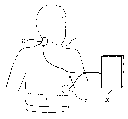
cardiac arrest according to an embodiment of the present invention;
Fig. 3 is a top elevational view of an electrode of the present invention
adhered
to the patient under cardiac arrest;
Fig. 4 depicts a representative hardware of the defibrillator 10 illustrated
in
Fig. 2 according to an embodiment of the present invention;
Fig. 5(a) is a perspective view of electrodes mounted upon the release liner
according to an embodiment of the present invention;
Fig. 5(b) depicts the actual site of electrode placement on one side of the
electrode to facilitate installation according to an embodiment of the present
invention;
CA 02482880 2004-10-13
WO 03/086537 PCT/IB03/01190
Fig. 6 is a diagram of the electrodes according to an embodiment of the
present invention; and,
Fig. 7 is a flow chart illustrating the operation steps of the defibrillation
system 10 in accordance with the present invention.
In the following description, for purposes of explanation rather than
limitation,
specific details are set forth such as the particular architecture,
interfaces, techniques, etc., in
order to provide a thorough understanding of the present invention. For
purposes of
simplicity and clarity, detailed descriptions of well-known devices, circuits,
and methods are
omitted so as not to obscure the description of the present invention with
unnecessary detail.
Now, a description will be made in detail in regards to this invention with
reference to the drawings.
Fig. 2 illustrates a defibrillator system 20 with a pair of electrodes 22 and
24
according a preferred embodiment of the present invention as it would be
applied to a cardiac
arrest victim 2. As shown in Fig. 2, one electrode 22 (hereinafter referred to
as "necktrode")
is positioned on the right side of the patient's neck 2, above the collarbone,
whereas the other
electrode 24 is positioned at the lower left base of the ribs. In particular,
the nectrode 22 may
be placed on the right side of the patient's neck, such that vertically the
top horizontal edge of
the necktrode 22 is approximately within 10 cm of the bottom of the patient's
right ear lobe
and horizontally the centerline of the necktrode 22 is approximately within 10
cm of the
vertical midline of the neck when viewing the patient 2 from the side.
Although the
placement of the necktrode 22 is shown in Fig. 2 for illustrative purposes, it
is to be
understood that the placement may be lower at the side of the neck, where the
neck and
shoulder join, or may be positioned in the front of the throat region above
the sternal notch or
the back of the neck area. The second electrode 24 can be placed quickly by
lifting the
patient's garment just enough to expose the second attachment area. It is
noted that the neck
region of the victim 2 below the ear and behind the jaw line as well as the
lower left base rib
region are conveniently accessible to a rescuer and a relatively hairless area
on many
individuals, thus requiring no hair or clothing removal to enable the rapid
attachment of the
electrodes 22 and 24 to the patient's body. Thus, the position of the
necktrode 22 in the
drawing should not impose limitations on the scope of the invention.
Referring to Fig. 3, the provision of delivering a defibrillating shock to a
cardiac arrest victim's heart according to the present invention will be
explained in a detailed
CA 02482880 2004-10-13
WO 03/086537 PCT/IB03/01190
6
description. In the prior art system, misapplied electrodes can allow the
electrical pulse or
current to flow along the chest wall, thus missing the victim's heart. As a
consequence, the
placement of electrodes is repeated, thus delaying the speed with which
defibrillation can be
performed on the patient. Moreover, experiments have revealed that the
electrical waveform
delivered by the conventional defibrillators do not flow directly from one
electrode to the
other electrode. Instead, currents leaving the defibrillator branch out to
complex paths,
including shunt pathways across the chest surface. Other currents transit the
heart through
complex routes that are to some degree steered by blood vessel routing and the
insulating
properties of a surrounding tissue, such as a lung tissue.
In contrast, the present invention provides the placement of the electrodes in
specific regions of the victim's body to optimize the defibrillator's
effectiveness. As shown in
Fig. 3, the electrode placement according to the present invention provides a
defibrillation
current flow between the nectrode 22 and electrode 24 in order to maximize the
efficiency of
the placement and to minimize the impedance caused by the chest bones and
surrounding
tissues. That is, the electrotherapeutic pulses are supplied directly to the
victim's heart along
the current pathway formed between the nectrode 22 and the electrode 24. The
necktrode 22
is placed to gain access to the blood pathway near the neck region (i.e.,
carotid artery and
jugular vein) that leads to the heart. The second electrode 24 is placed over
or slightly below
the heart's apex on the victim's left chest, on a vertical line below the
armpit and horizontally
at the approximate bottom of the rib line. This position is easily accessible
by pulling up the
victim's shirt or other garment on the left side with one hand while
positioning the electrode
24 with the other hand. The inventive electrodes 22 and 24 are also
substantially small
enough to be used in this manner on patients of all ages, including children
and adults. On
infants, the placement of the electrodes 22 and 24 may shift to the anterior-
posterior of the
body, such that one electrode is centered on the chest and the other electrode
is centered on
the back of the infant.
In addition, the present invention renders the placement of the electrodes 22
and 24 for defibrillation without violating the privacy of women as the
patient's chest does
not have to be completely bared. In the prior art system, the patient's bra
has to be removed,
especially bras with wires embedded therein, as they interfere with
administering the
defibrillating shock. These wires impose fewer problems in the present
invention as the
necktrode 22 is placed so that the wire orientation is relatively normal to
the current pathway.
Hence, the placement of the electrodes 22 and 24 according to the present
invention allows
CA 02482880 2004-10-13
WO 03/086537 PCT/IB03/01190
7
defibrillating a female patient without removing her bra. This in turn
eliminates the
reluctance of a rescuer when removing a stranger's clothing.
Fig. 4 is a simplified block diagram of the defibrillator 20 illustrated in
Fig. 1
in accordance with the embodiment of the present invention. However, any
number of
commercially or publicly available defibrillator configured to generate a
defibrillation shock
can be utilized in various implementations in accordance with the preferred
embodiment of
the present invention. The defibrillator 20 may include an electrocardiagram
(ECG) front end
32, a timer 34, a defibrillation activation button 36, a HV switch 38, a
controller 40, a display
42, an energy storage capacitor network 44, a voltage charger 46, and a
battery 48. The ECG
front end 32 is connected to the electrodes 22 and 24 that are placed on the
patient and
operates to amplify, filter, and digitize (using am analog to a digital
converter) an electrical
ECG signal generated by the patient's heart. The detected ECG samples are
provided to the
controller 40, which runs a shock advisory algorithm for detecting VF or other
shockable
rhythm requiring treatment by the defibrillation shock. The ECG front end 32
is also capable
of measuring the patient impedance across the electrodes 22 and 24 using a low
level test
signal that is a non-therapeutic pulse to measure the voltage drop across the
electrodes 22 and
24. The detected patient impedance is analyzed by the controller 40 to
determine the
appropriate energy level desired to be delivered to the patient. As the
necktrode 22 is placed
directly over major blood vessels close to the contact surface, the ability to
sense ECG
signals to detect impedance can be improved compared to the prior art system.
The timer 34 is connected to the controller 40 for providing a defibrillation
pulse interval or duration when delivering the defibrillation pulse across the
electrode pair 22
and 24. The activation button 36 is connected to the controller 40 to enable
the user to
activate the delivery of a defibrillation pulse across the electrodes 22 and
24 when the VF or
other shockable rhythm is detected. The activation button 36 can function in
both AED and
manual modes in the preferred embodiment. The display 42, connected to the
controller 40, is
preferably a liquid crystal display (LCD) and provides audio and visible
feedback to the user.
The battery 48 provides power for the defibrillator 20 and in particular for
the
voltage charger 46, which charges the capacitors in the energy storage
capacitor network 44.
The capacitors in the energy storage capacitor network 44 may be charged to
2300 volts or
more. The energy storage capacitor network 44 includes a plurality of
capacitors and resistors
that are arranged in series or parallel arrangement, or a combination of
series and parallel
arrangement to supply a plurality of voltage level outputs across the
electrodes 22 and 24. It
will be apparent to those skilled in the art that a variety of RC arrangements
can be
CA 02482880 2004-10-13
WO 03/086537 PCT/IB03/01190
implemented to generate different voltage levels. For example, a series
resistance of
approximately 20 ohms may be inserted in series to deliver electrical power
from the battery
48 to the patient. For very high impedance patients, this resistor is shorted
during discharge
in order to deliver high currents for effective defibrillation. Using lower
total delivered
energies enables the present system to operate safely for adults and children
without
requiring the operator to differentiate between the two. Therefore, by
selecting an appropriate
energy level according to the patient-impedance and the desired energy level
determined by
the controller 44, a wider range of energy levels can be generated from low to
high, without
exceeding the maximum threshold value that may be harmful to the patient.
Additional parallel capacitors and resistors may be added as needed to the
energy storage capacitor network 44 to increase the total delivered energy of
the waveform to
the patient. It should be noted that various hardware configurations readily
apparent to those
skilled in the art can be used for the energy storage capacitor network 44.
Alternatively, the
function of the energy storage capacitor network 44 can be performed by
functionally
equivalent circuits, such as a digital processor circuit or an application-
specific integrated
circuit (ASIC).
The energy storage capacitor network 44 is connected to the HV switch 38.
Under the control of the controller 40, the HV switch 38 is configured to
sequentially deliver
the defibrillation pulse across the pair of electrodes 22 and 24 to the
patient in the desired
polarity and duration. It should be noted that the HV switch 38 could be
adapted to deliver a
single polarity (monophasic), both negative and positive polarities (biphasic)
or multiple
negative and positive polarities (multiphasic) in the preferred embodiment.
In operation, the controller 40 uses the information received from the ECG
front end 32 and/or the timer 34 to control the shape of the waveform of the
defibrillation
pulse delivered to the patient in real time. That is, the total delivered
energy of the waveform
can be controlled by selecting an appropriate pulse parameter in response to
the information
received from the ECG front end 32. Here, the defibrillation pulse delivered
to the patient
may be a fixed level, or a number of defibrillation pulses at different energy
levels. This can
be achieved by selecting the appropriate voltage level of the energy storage
capacitor
network 44 from the set of configurations to deliver the desired impedance-
compensated
defibrillation pulse to the patient. To achieve this, the controller 40 sends
a voltage control
signal to adjust the charge voltage on each capacitor in the energy storage
capacitor network
44 for a subsequent discharge. After each discharge, the patient's heart is
monitored
CA 02482880 2004-10-13
WO 03/086537 PCT/IB03/01190
9
simultaneously using the ECG front end 32 to determine if more defibrillation
pulses are
needed. If so, another set of defibrillation shocks is administered to the
patient.
Fig. S(a) is a perspective view of a release liner 100 and a pair of
electrodes 22
and 24 according to an embodiment of the present invention. The electrodes and
release liner
operating in accordance with the present invention may include various
embodiments of
medically packaged electrodes described in U.S. Patent Serial No. 09/954.750,
filed on
September 14, 2001, entitled "Medical Electrode and Release Liner
Configurations
Facilitating Packaged Electrode Characterization," assigned to the same
assignee, the
teachings of which are incorporated herein by reference.
Briefly, the release layer 100 may comprise silicon-coated paper, polyester,
polypropylene, polyethylene, and/or other non-stick materials, in a manner
well understood
by those skilled in the art. The opening 120 of the release layer 100 may be
cut, stamped, or
punched out using conventional techniques, so it can be performed in a variety
of ways. The
release layer 100 may further include a nonconductive, moisture-permeable
and/or moisture-
absorbent membrane 140. The electrodes 22 and 24 having at least one opening
22a and 24a,
respectively, may comprise a conductive foil layer that resides in a
conductive adhesive
layer. The conductive adhesive layer may include a conductive gel layer, such
as a hydrogel
layer, or other layer having electrical properties. One electrode 22 may be
placed or
positioned upon the release layer 100 so that the electrode's hydrogel layer
covers the release
layer's opening 120. Similarly, the other electrode 24 may be placed or
positioned upon the
release layer. The placement of the electrodes 22 and 24 upon the release
layer allows the
electrodes' hydrogel layers to contact the moisture-permeable membrane 140 via
the release
layer's opening 120. When the electrodes 22 and 24 have been mounted upon the
release liner
100, the defibrillator 20 may test the electrical path between the electrodes
22 and 24 by
measuring the impedance level. If the measured impedance level is greater than
a predefined
threshold or range, the defibrillator 20 will indicate that the electrodes 22
and 24 may be unfit
for use. The electrodes 22 and 24 may also be handheld paddle electrodes that
are used with a
manual defibrillator. The total surface of the electrodes is approximately 70
square
centimeter for the necktrode 22 and 80 square centimeter for the other
electrode 24.
However, it should be noted that another size of electrodes from the one shown
can be used
successfully in accordance with the techniques of the present invention. The
electrodes 22
and 24 may fiirther include an insulating cover layer and a lead wire that
facilitates coupling
to the defibrillator 10.
CA 02482880 2004-10-13
WO 03/086537 PCT/IB03/01190
It should be noted that packaged electrodes according to the present invention
may include a wrapper, covering, label, or the like that includes an
expiration date by which
electrodes must be used. An illustrative drawing showing the actual site of
electrode
placement also may be included on one side of the electrode to facilitate
installation, as
5 shown in Fig. S(b).
Fig. 6 is a graph illustrating the electric current density of the electrode
22 and
24 of Fig. 5 when the electrodes 22 and 24 are mounted upon a patient's body.
Those skilled
in the art will understand that the current flows more easily between an
electrode and a
patient's body near the electrode's edges. Thus, the current density increases
and peaks at the
10 outer edge or border of the electrode's foil layer. However, in the
embodiment, the presence
of an opening or void 240 in the electrode's foil~layer 220 affects the
electrical current
flowing through or within the electrode. The void 240 may comprise a circular,
elliptical, or
other shaped opening that is generally disposed within a central region of the
foil layer 220.
As shown in Fig. 6, the current density drops to a minimum value in the region
defined by the
void 240, and an additional boundary at which a current density peak occurs in
the presence
of a void 240. As a result, the presence of one or more voids in the foil
layer 220 may
decrease the effective shock impedance of the electrodes 22 and 24. Therefore,
the
defibrillator 20 in accordance with the present invention can operate at a
lower level of
energy to deliver the electrical pulse to the victim's heart from the surface
of the skin.
Fig. 7. is a flow chart illustrating the operation steps of delivering an
impedance-compensated defibrillation shock according to the present invention.
Initially, a
test is performed to determine whether the electrodes 22 and 24 are operative
by sending an
impedance between the electrodes 22 and 24 through the release liner. If the
electrodes 22
and 24 are not damaged, the user can then peel off from the adhesive layer and
place on the
patient's skin as shown in Fig. 3. At the same time, the voltage charger 46 of
the defibrillator
20 operates to charge each capacitor of the energy storage capacitor network
44 to a
predetermined percentage of the voltage level in order to deliver a
defibrillation shock.
Thereafter, in step 300, the ECG front end 32 detects a shockable rhythm,
i.e., ventricular
fibrillation (VF). If no shockable rhythm is detected, the defibrillator 20
continues to detect
the ECG information. If a shockable rhythm is detected, the patient impedance
is measured
by measuring a low-level test signal or delivering a non-therapeutic signal in
step 320. The
detected shockable rhythm is forwarded to the controller 40 of the
defibrillator 20, then the
energy level of the defibrillation shock, which may include a series of
successive
defibrillation shocks at a predetermined interval, to be delivered to the
patient is determined.
CA 02482880 2004-10-13
WO 03/086537 PCT/IB03/01190
11
The energy level may be determined by the operator manually, or it can be
determined by
automatically utilizing a common protocol known in the art.
In step 340, the patient impedance is considered by the controller 40 to
select
the appropriate energy level output from the set of configurations in the
energy storage
capacitor network 44. For example, it may be desirable to deliver a higher
energy level to a
high patient impedance and a lower energy level to a low patient impedance.
Here, the
controller 40 also determines the polarity and duration of the defibrillation
shock. After
determining the desired energy level output, the controller 40 sends a signal
to the energy
storage capacitor network 44 to implement the desired configuration to
discharge the desired
energy level of defibrillation shock. Thereafter, the controller 40 sends a
signal to the HV
switch 38 to actuate the switches to discharge the desired defibrillation
shock to the patient in
step 360. Alternatively, the controller 40 may notify the operator via the
display 42 to press
the shock button 36 to actuate manually the delivery of the defibrillation
shock to the patient.
After the discharge of defibrillation shock, the patient's heart is monitored
to determine
whether a subsequent defibrillation shock is necessary. If so, the above steps
may be repeated
to deliver the subsequent defibrillation shock.
Having thus described the preferred embodiment of a system and method for
delivering an electric pulse, waveform, or shock to the patient's heart, it
should be apparent to
those skilled in the art that certain advantages have been achieved. In
particular, the present
invention saves the time previously needed to struggle with clothing removal,
thus improving
survival odds. The attachment areas in accordance with the present invention
minimize the
effects of excessive body hair, which prevents effective electrode contact
with the patient's
skin by eliminating the need to shave a patient's chest prior to the
attachment of electrodes.
The inventive electrodes are smaller in size and thus easier to store, deploy,
and attach to
both children and adults. As a result, the same defibrillation protocol may be
used on children
or adults. The smaller electrode also enables additional miniaturization of
the entire
defibrillation system. Also, the present invention overcomes or minimizes a
rescuer's
reluctance in removing clothing from unconscious patients, especially from
female patients in
fear of violating their privacy.
Furthermore, the inventive system reduces the artifact in the ECG signal
caused by movement due to the cardio pulmonary resuscitation (CPR) operation.
During the
rescue attempt, electrodes are used to gather ECG signals for analysis from
the patient's heart.
When a rescuer performs chest compressions as part of doing CPR on the
patient, the
resulting chest movement tends to disturb the electrodes placed on the chest
area in the prior
CA 02482880 2004-10-13
WO 03/086537 PCT/IB03/01190
12
art system. This is undesirable as the movement of the electrodes on the chest
skin area
generates interfering electrical noise or artifacts, which corrupts the ECG
signal. Therefore,
the placement of the electrodes according to the embodiment of the present
invention
minimizes such artifact and thus enhances the analysis of the ECG signal
during a CPR
operation. The ability to analyze the ECG more accurately during a CPR
operation reduces
the time that CPR must be interrupted during the resuscitation, thereby
increasing the chances
of a successful rescue attempt.
While the preferred embodiments of the present invention have been
illustrated and described, it will be understood by those skilled in the art
that various changes
and modifications may be made, and equivalents may be substituted for elements
thereof
without departing from the true scope of the present invention. In addition,
many
modifications may be made to adapt to a particular situation and the teaching
of the present
invention without departing from the central scope. Therefore, it is intended
that the present
invention not be limited to the particular embodiment disclosed as the best
mode
contemplated for carrying out the present invention, but that the present
invention include all
embodiments falling within the scope of the appended claims.